1
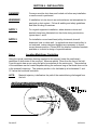
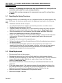
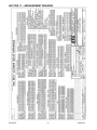
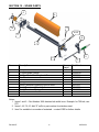
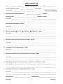
PIT VIPER CONVEYOR BELT PRIMARY CLEANER SAFE WORKING PROCEDURES (SWP) INSTALLATION MANUAL Revision A B C D E Revision E Description of Change First Issue CR 2430, dimension correction, update graphics Updated Melbourne Address & Removed SA Address Final Checklist Updated Items 4 & 5 Reversed Revised Drawing F0347 - revision D 1 Changed By TT TT SH SH KO Date 31/3/09 3/4/09 3/08/09 15/04/10 14/03/11 14/03/2011 ENGINEERING SERVICES and SUPPLIES OFFICE DETAILS ESS HEAD OFFICE 11-13 TRADERS WAY PO BOX 121 CURRUMBIN QLD 4223 P: (07) 5589 2000 F: (07) 5598 1353 ESS MACKAY 1 PROGRESS STREET PO BOX 5755 MACKAY MC QLD 4740 P: (07) 4952 4600 F: (07) 4952 4717 ESS PERTH 19 CLAVERING ROAD BAYSWATER WA 6053 P: (08) 9370 3155 F: (08) 9272 5130 ESS MAITLAND UNIT 2 BARTON COURT 6 JOHNSON STREET MAITLAND NSW 2320 P: (02) 4932 3544 F: (02) 4932 3611 ESS WOLLONGONG 1/20 DOYLE AVENUE PO BOX 343 UNANDERRA NSW 2526 P: (02) 4272 4422 F: (02) 4272 4434 ESS MELBOURNE 4/314 Governor Road BRAESIDE VIC 3195 P: (03) 9580 0388 F: (03) 9587 5199 ESS EMERALD 11/115 ROBERTS STREET EMERALD QLD 4720 P: (07) 4982 4855 F: (07) 4987 5118 ESS GLADSTONE 2/34 CHAPPLE STREET PO BOX 1475 GLADSTONE QLD 4680 P: (07) 4972 3759 F: (07) 4972 2866 ESS ADELAIDE P: (08) 8262 8955 F:(08) 8262 4944 ESS KALGOORLIE 4/235 HAY STREET PO BOX 10471 KALGOORLIE WA 6430 P: (08) 9021 7991 F: (08) 9021 7291 ESS MOUNT ISA 6 TRADERS WAY PO BOX 1554 MT ISA QLD 4825 P: (07) 4749 4580 F: (07) 4749 3019 CUSTOMER SERVICE NUMBER 1800 074446 TOLL FREE FROM ANYWHERE IN AUSTRALIA Revision E 2 14/03/2011 INDEX Section 1 2 3 4 5 6 7 8 9 10 11 12 13 Revision E Topic Safety Introduction Preparation for Installation Installation Spring Tensioner Tensioner Adjustment Procedure Maintenance Procedures Commissioning Operator Training Trouble Shooting Installation Arrangement Drawing Spare Parts Final Checklist 3 Page 4 5 6 7 10 12 13 14 15 16 17 18 19 14/03/2011 WARRANTY NOTE ESS WARRANTS the PIT VIPER Primary Cleaner to be free of defects both in materials and workmanship for a period of 12 months from the date of despatch of the product from the ESS factory. The warranty given by ESS in this regard will extend only to replacing or repairing product shown to be defective. The warranty also is subject to the following restrictions: (a) Installation of the product contrary to the instructions contained in the supplied manual will void such warranty absolutely; (b) The warranty will not extend to any liability for injuries incurred and which result from the use of the product contrary to the instructions in the manual; (c) Save as prescribed by law, ESS will not be liable for any damage sustained by a purchaser or a third party by way of consequential loss arising out of defects in the product. You are asked to note that ESS offers purchasers a service whereby either: (a) ESS will install the product and certify the correctness of such installation, or (b) ESS WILL certify the correctness or otherwise of the installation of the product by third parties. This certification service is designed to ensure that you obtain the full benefit of the ESS warranty hereby provided. If you would like to take advantage of the installation certification service provided, please contact ESS regarding the service. THE CONTENTS OF THIS MANUAL ARE COPYRIGHT TO: ESS ENGINEERING SERVICES AND SUPPLIES PTY LTD ALL RIGHTS RESERVED Information contained herein is for use in the operation of the PIT VIPER PRIMARY CLEANER, purchased from ESS and cannot be passed on to any other party without express permission, in writing, from ESS. Visit the ESS Website www.esseng.com.au to register your warranty. Revision E 4 14/03/2011 SECTION 1 – SAFETY All equipment installed on or around a conveyor belt must comply with AS 1755 – 2000 Conveyors – Safety requirements. Ensure that only suitably qualified and trained personnel install and service this product, and that all site and statutory safety procedures are followed. The PIT VIPER PRIMARY CLEANER is designed to be quickly and easily serviced by appropriate personnel, however under no circumstances should any personnel attempt installation or service of this equipment whilst the conveyor belt is running. The conveyor belt drive and any associated equipment must be shut down and locked out according to plant safety procedures before attempting work requiring access to or opening of the chute or conveyor enclosure. Contact with a moving conveyor belt and its drive components can result in serious injury or death. The PIT VIPER Cleaner may be inspected or the tension adjusted with the belt running as long as suitable visual access is available, but the service person should never reach into or enter the conveyor enclosure. No other service work is able to be carried out with the conveyor running. Shut down and lock out the conveyor for any work requiring any part of the body to enter the conveyor enclosure, or be exposed to moving components. The following hazards that may be present when installing this equipment: X Hazard Moving Conveyor - ISOLATE Hot Work Working at Heights Heavy Lift Persons Working Overhead Persons Working Below Electrical & Cabling Pinch Points Trip Hazards Hazard Other: Other: Other: Other: Other: Other: Other: Other: Once hazards have been identified, the installer should undertake and document a comprehensive Job Hazard Analysis according to site requirements and good safe-working practice. The installer must identify all hazards and apply appropriate controls before proceeding with the installation or servicing of this equipment. Revision E 5 14/03/2011 SECTION 2 – INTRODUCTION The PIT VIPER is a conveyor belt primary cleaner. It is normally mounted on the face of the conveyor belt head pulley and is designed to peel off the thick layer of loosely adhering material that often accounts for up to 80% of carryback. The PIT VIPER Primary is normally used in conjunction with at least one secondary cleaner, such as the Inline Premium Secondary Cleaner, and often with a water spraying system. The one piece blade is made of cast urethane, with an aluminium extrusion insert for locating to the cleaner mainframe. The blade is secured to the mainframe with one fixed and one removable pin. Blade replacement is quick and easy. Important Points to Remember Concerning the PIT VIPER Primary are; 1. The cleaner is directional - it will only clean the belt travelling in the design direction. However, the cleaner will not be damaged or affected by belt direction reversal. 2. The cleaner is suitable for use on crowned head pulleys and damaged or grooved belts. The urethane blades quickly conform to the belt profile. 3. For slow moving belts, the cleaner should be positioned lower on the head pulley to ensure the blades are clear of the main material flow. Revision E 6 14/03/2011 SECTION 3 - PREPARATION FOR INSTALLATION 1. CHECK INSTALLATION DRAWINGS - Ensure that you have the correct drawings and equipment for your conveyor(s). 2. PRE-ASSEMBLE THE CLEANER(S) AND MOUNTS - Do this in your workshop or similar free area, rather than at the Conveyor. This will enable you to: verify all required equipment is present familiarise yourself with the cleaner assembly allow you to plan the installation, reducing installation time. 3. ASSEMBLE THE NECESSARY TOOLS & SAFETY EQUIPMENT REQUIRED FOR THE INSTALLATION 4. OBSERVE THE CONVEYOR WHILE RUNNING AND CONVEYING MATERIAL Observe the material trajectory Observe the belt direction - does it reverse or roll back? Observe the belt splice condition Does the belt run true, or track off to one side? Is the Head Pulley out-of-round? Consult ESS if any UNUSUAL conditions are observed in the above. These conditions may result in recommendation of a different installation position or even a different cleaner. Revision E 7 14/03/2011 SECTION 4 - INSTALLATION DANGER! Conveyor must be shut down and locked out before any installation or service work is performed. WARNING! If installation is to be done in an enclosed area, test atmosphere for gas level or dust content. Follow all welding and safety guidelines and Safe Working Procedures. NOTE 1 For original equipment installation, where cleaner cutouts and brackets have been fabricated into the chute during construction, ignore steps 1 and 2 . NOTE 2 For installation on enclosed head pulley chutework, draw all dimension lines on chute wall. In applications where head pulley is not enclosed, custom designed brackets are necessary to ensure correct cleaner position. Contact ESS for details of standard brackets available or to assist in design of special brackets. Step 1. Locating Mainframe Centreline Using the typical installation drawing supplied in this manual, locate the mainframe’s centreline on both sides of the conveyor. Measure radially 75mm from the face of the belt. From this point draw an arc using the pulley’s centreline as the centre point. The centreline of the mainframe can be located anywhere along the radius as long as the blade does not lie in the material’s trajectory. The optimum position is for the blade tip to be between 0 and 15 below the horizontal centreline. NOTE: Revision E Material trajectory is defined as the path of the material being discharged from the belt. 8 14/03/2011 Verify Mainframe Position before Proceeding Position the mount and tensioner assembly over the centreline marks for the mainframe. Verify that the mounts fit, and that adequate room is available to tension the cleaner. If used, position the CYA door frame to ensure it fits. If mounts, tensioner or door frame interfere with structural members, it may be necessary to locate the cleaner elsewhere on the 75mm offset radius. If the tensioner only interferes, remember that the tensioner can be reverse assembled, or that the mount and tensioner assembly may be rotated about the cleaner centre line. The side of the chute from which inspections, adjustments and servicing will be carried out will be referred to as the Operator Side. The opposite side of the chute will be referred to as the Far Side, and will only require access (other than at installation) on large belts where an optional second tensioner assembly may be added for more uniform application of tensioning force. Step2. At the selected mainframe mounting positions, mark out and cut the mainframe and mount fastener holes (if required) in each side of the chute. Refer to the installation drawing at the back of this manual. If a CYA door is to be installed, use the door frame as a template to mark the door cut-out on the operator side. Proceed to cut the door hole, but ensure that the marked centre lines of the cleaner are not totally removed - you will need these to position the mainframe. Fit the CYA door frame over the cutout and tack weld in position. If a stand-off bracket is to be bolted over a CYA door, the mounting holes also need to be cut or drilled. Step 3. The Pit Viper Mainframe is a fabricated member comprising a length of DN40 steel pipe, with a steel flat bar for attachment of the blade. On wider belts, an additional flat bar stiffener is added. Remove the blade from the mainframe. Do this by removing the lock pin, then sliding the blade clear of the fixed pin at the opposite end. The blade will then come free of the mainframe. Insert the mainframe without the blade through the mount or CYA door cutout in the operator side of the chute and continue until the far end of the mainframe passes through the far side mount cutout. Ensure that the removable pin end of the mainframe is toward the operator side of the chute. Be careful not to lose the lanyard and lock pin from the mainframe. Step 4 Slide the operator and far side mounts on to the mainframe ends, then clamp or loosely bolt the mounts to the chute walls. If a stand-off bracket is to be used over a CYA door, and the cutout has been made, fit the operator side mount to the appropriate stand-off bracket, and clamp or bolt the stand-off bracket in the desired position. Position the mainframe so that the blade mounting flat bar is centred on the belt. Revision E 9 14/03/2011 Step 5. Check the position of the mainframe. Is the centre line of the mainframe positioned 75mm from the belt face? Is the mainframe level, or equal to the pulley shaft? Fit the blade to the mainframe by locating it on the flat bar, then sliding until the far end of the blade engages on the fixed pin. Fit the removable pin to the operator end of the blade / flat bar interface. Rotate the mainframe until the blade contacts the belt. Does the blade tip touch evenly across the belt? For crowned head pulleys, ensure that the outside ends of the blade are an equal distance from the belt, whilst the centre of the blade is touching. Again, these gaps will quickly close on tensioning. If any questions above have been answered “NO”, take appropriate action to correct the installation. If all questions are answered “YES”, proceed. Step 6. Securely bolt the cleaner mounts, brackets and weld the CYA door frame to the chute wall. If not already done, fit the tensioner assembly(ies) to the mount(s). Centre the blade to the head pulley (or the belt if it is correctly tracked). All ESS cleaners are designed to clean an area narrower than the actual belt width. This is to allow for a small amount of lateral movement of the belt and to protect the edge of the belt from possible damage. Lateral movement of the mainframe is prevented by the tensioner’s locking hub and a lock collar on the far side mount. Where optional dual tensioners are used, the tensioner locking hubs only are used. Lock these items in position, allowing about 1-2mm of end float in the cleaner mainframe. Step 7. WHERE A CYA DOOR IS FITTED. Measure the position of the mainframe in relation to the CYA door frame. Mark this position on the CYA door rubber cover, and cut a neat hole, approximately 50mm diameter in the cover. Cut a straight line from this hole to the nearest edge of the rubber cover. Install the rubber cover over the mainframe pipe, and push into place on the door frame. Anchor the loose end of the cover lanyard. Revision E 10 14/03/2011 SECTION 5 - SPRING TENSIONER The ESS PIT VIPER Primary Cleaner is mounted to the conveyor structure via ESS Flex Mounts. The Flex Mount is a steel mount plate with a urethane bush. Other bush materials are available for special applications. The Spring Tensioner unit attaches to the existing mount bolts. The Spring Tensioner is a simple, robust and reliable blade tensioning unit. It can be assembled to tension in either the clockwise or anti-clockwise direction and has multiple mounting positions for each direction. Anti – Clockwise Tensioning Clockwise Tensioning Figure 1 5.1 INSTALLATION OF THE SPRING TENSIONER Operating Arm Flex Mount with Bush Spring Anchor Plate Revision E Adjusting Rod 11 14/03/2011 Step 1 Fit the anchor plate to the mount using two of the existing M16 mount bolts. Ensure that the plate is in the correct orientation for the desired tensioning direction. The anchor plate can be installed on the opposite side mount holes for tensioning in the opposite direction. The anchor plate and tensioner assembly can also be turned upwards to suit site restrictions. Step 2 Slide the operating arm onto the cleaner mainframe, again ensuring that it is in the correct orientation for the desired tensioning direction. Step 3 Insert the threaded end of the adjusting rod through the operating arm slot, with the clevis end toward the anchor plate. Step 4 Fit the adjusting rod clevis onto the anchor plate pin and secure with clip provided. Step 5 Fit spring, washer, nut and locknut to the threaded end of the adjusting rod. Only run the adjusting nut a few turns onto the adjusting rod. Do not try to adjust or compress the spring yet. Step 6 Using a pipe wrench or similar, grip the mainframe and rotate the cleaner until the blade tip is lightly touching the belt. With the operating arm fully retracted against the spring, lock the operating arm onto the cleaner mainframe by tightening the two lock screws. Ensure that the operating arm hub is 1-2mm clear of the mount to allow free rotation without excessive lateral movement of the mainframe. Step 7 Whilst still supporting the cleaner with the pipe wrench, adjust the nut (not locknut) against the spring until the spring just begins to compress. Release the pipe wrench. Step 8 For cleaners fitted with optional dual tensioners, repeat above procedure for other side. For cleaners with one tensioner only, fit the locking collar onto the far end of the cleaner mainframe, again locking it into position 1-2mm clear of the mount. Revision E 12 14/03/2011 SECTION 6 – SPRING TENSIONER ADJUSTMENT PROCEDURE Note: The Spring Tensioner is mounted externally to the conveyor chute, and as such is normally able to be adjusted with the conveyor in service. Under no circumstances should any person reach into or enter a conveyor enclosure while the belt is running. For any conveyor belt cleaner service, maintenance or adjustment that requires entry to the conveyor enclosure by any part of the body, first ensure that the conveyor is shut down and locked out to site safety procedures. Warning: Contact with moving conveyor components can result in severe injury or death. To adjust the Pit Viper Spring Tensioner: Loosen the locknut away from the adjusting nut on the adjusting rod. Turn the adjusting nut until the cleaner blade is pressed against the belt, and the spring begins to compress. Continue until the spring is compressed to the length shown in the following table 1. Once the correct spring compression is achieved, run the locknut up against the adjusting nut, and use two wrenches to tighten the nuts together. For cleaners with optional dual tensioners, repeat this procedure on the opposite side. Table 1 Belt Width 450 500 600 750 900 1050 1200 1350 1500 1800 Spring Length 95 95 92 92 89 89 86 83 80 (92 **) 77 (89**) ** Note: For Cleaners with optional dual tensioners. The settings shown are for each tensioner. Revision E 13 14/03/2011 SECTION 7 – PIT VIPER AND SPRING TENSIONER MAINTENANCE PROCEDURES 5.1 Warning: The following procedures may only be performed on a conveyor that is shut down and locked out to site safety procedures. Contact with a moving conveyor or its components can result in serious injury or death. Resetting the Spring Tensioner The Spring Tensioner can occasionally run out of adjustment before the cleaner blade is fully worn. In this case, the tensioner can be reset to the adjustment start point in the following way: Shut down and lock out the conveyor. For optional dual tensioner cleaners, perform this procedure one side at a time. Release the lock nut and run it fully out. Gradually release the adjusting nut. In some cases the cleaner will slowly de-adjust with the nut, and in others it may stick, then drop suddenly. Keep fingers clear. When the adjusting nut is fully retracted, grip the cleaner mainframe with a pipe wrench, and release the lock screws in the operating arm. Rotate the cleaner mainframe so that the blade tip lightly touches the belt and hold it in this position. By hand, fully retract the operating arm against the spring and adjusting nut. Re-tighten the lock screws in the operating arm. Release the pipe wrench from the mainframe and follow the adjustment procedure in the previous section. For cleaners with optional dual tensioners, this procedure is even easier. The opposite side tensioner will hold the cleaner in position, so the use of a pipe wrench is not necessary, but the procedure should be carried out on both sides before retensioning to equalise the tensioner positions. 5.2 Blade Replacement Shut down and lock out the conveyor. Release the locknut and run it fully out (both sides for a dual tensioner cleaner). Gradually release the adjusting nut (both sides for dual tensioners). In some cases the cleaner will slowly de-adjust with the nut, and in others it may stick, then drop suddenly. Keep fingers clear. Remove the cleaner blade. Remove the lock pin and withdraw the blade from the mainframe. Fit the new cleaner blade. If the tensioner prevents the new blade from fitting to the belt, reset the tensioner by reversing the procedure described above. Slide the new blade onto the mainframe until it engages the fixed pin. Refit the lock pin. Adjust the tensioner(s) as described in the previous section. Return the conveyor to service. Revision E 14 14/03/2011 SECTION 8 - COMMISSIONING Step 1. RE-CHECK ALL INSTALLATION DIMENSIONS AND SETTINGS Double check the items in previous sections - safety - preparation - installation. Step 2. IS THE BELT EMPTY? Make sure there are no foreign objects such as tools or clean-up debris left on the belt. They may damage the belt cleaners or clog up the conveyor systems. Step 3. PLACE CONVEYED PRODUCT ON THE BELT Place some material on the belt before starting up system. This helps to quickly “Wear in” the blades and reduce the initial friction between the belt and the blades. Handfuls of conveyed material spaced along the belt will do. The belt may also be moistened with water. Step 4. START THE CONVEYOR Follow the established safety rules. Step 5. OBSERVE THE CLEANING ACTION Observe the belt and the action of the cleaner. Place material on the belt. Look for uniform blade contact on the belt. Run for 5 minutes to get a good idea of the action and the effect of the splices on the belt cleaner. Step 6. DEMONSTRATE THE SYSTEM TO THE OPERATING SUPERVISORS AND CREW Call the supervisors responsible for maintenance and operation to the site. Make a short run of the system, putting material on the belt. Show the operator how to adjust and operate the system. Step 7. SECURE THE SYSTEM FOR PRODUCTION Follow plant procedure to secure the conveyor for actual production. Revision E 15 14/03/2011 SECTION 9 - OPERATOR TRAINING The decision to purchase ESS cleaning equipment has put within easy reach the reality of a clean plant. The last step is the correct training of personnel to maintain and service the equipment or employ ESS on a contract basis to maintain the cleaners so that they remain at optimum efficiency. The benefits of efficient cleaners outweigh the cost of maintaining the cleaners many times. If you wish to have your cleaning system maintained on a regular contract basis, contact ESS. If not, train your own personnel as follows: 1. Adhere to all local safety rules. 2. Give a “Hands On” instruction with the conveyor system shut down. 3. Give a “Hands On” instruction with the conveyor system running. 4. All service must be recorded and given to a person of responsibility. 5. Encourage the person being trained to look for possible problems developing on the system, eg. belt tracking excessively, tears or damage to belt, seized idlers, missing bolts, etc. A warning to the maintenance department to rectify small problems can save the company a lot of money in repairs and production costs. 6. Impress how important it is to maintain and service the cleaners correctly. Revision E 16 14/03/2011 SECTION 10 - TROUBLE SHOOTING PROBLEM - Blade folds through on start-up. CAUSE Incorrect angle of installation dimensions Excessive tension attack Belt running dry Poor belt condition SOLUTION /. Relocate mounts so that the shaft is 75mm radial from the belt face on the head pulley Relax blade tension to maximum tension recommended in installation instructions Always place material on the belt for start-up or a little water if material is unavailable Repair belt, dress spices to smooth contour PROBLEM - Mainframe bent. CAUSE Mainframe undersized SOLUTION Stiffened mainframe required. Contact ESS for assistance Excessive tension Relax blade tension to maximum tension recommended in installation instructions Blades folded through See above Material build-up between blades/ Increase frequency of inspection and service once a mainframe and belt week Normal deflection A small amount of deflection is considered normal. Contact ESS if excessive deflection occurs PROBLEM - Higher blade wear rate than estimated. CAUSE Cleaner over-tensioned Incorrect blade material SOLUTION Tension cleaner enough to clean the belt only Contact ESS for re-appraisal PROBLEM - Insufficient cleaning - too much carryback. CAUSE Cleaner under-tensioned Build-up on blade Cleaner overloaded Secondary cleaner not functioning correctly Revision E SOLUTION Re-tension cleaner Rap blades against belt. Increase service frequency Add additional secondary cleaner Service the secondary cleaner 17 14/03/2011 SECTION 11 – ARRANGEMENT DRAWING Revision E 18 14/03/2011 SECTION 12 – SPARE PARTS 5 2 10 3 4&5 4 8 1 9 6 7 Item Description 1 2 3 4 5 6 7 8 9 10 Pit Viper Mainframe Pit Viper Blade Orange Pit Viper Blade Retaining Lock Pin Flex Mount Flex Bush FRAS Urethane Spring Tensioner Anchor Plate Spring Tensioner Adjusting Rod c/w Nuts Spring Tensioner Operating Arm Spring Tensioner Spring Lock Collar No. Req’d 1 1 1 2 2 1 1 1 1 1 Part Number 15330XXX 33900XXX 33900001 09010057 09010055FM 09010334 09010331 09010330 09010335 09010041 Notes : 1. Items 1 and 2 – Part Number XXX denotes belt width in cm. Example: for 750 belt, use 075. 2. Items 1,4,6,7,8,10. Add “S” suffix to part number for stainless steel. 3. Item 5 is available in a number of materials – contact ESS for further details. Revision E 19 14/03/2011 FINAL CHECKLIST Site: ____________________________ Number: ____________________ Site Equipment No./Location: _________________________ Date: ___________________ Site Contact: _________________________ Completed By: _____________________________________ (Circle Yes or No Below) 1. Was equipment to ESS Specification? ______________________________ Yes/No Drawing No. Ref:________________________________________ Attached? Yes/No If No, WHY _______________________________________________________________________________ ________________________________________________________________________________________ Will this affect performance? Yes/No If Yes, WHY ______________________________________________________________________________ ________________________________________________________________________________________ 2. Was this a standard service inspection installation? Yes/No If No, WHY _______________________________________________________________________________ ________________________________________________________________________________________ ________________________________________________________________________________________ 3. Was work carried out as per procedure and JSA? Yes/No If No, WHY _______________________________________________________________________________ ________________________________________________________________________________________ 4. Is equipment fit for commissioning? Yes/No If No, WHY _______________________________________________________________________________ ________________________________________________________________________________________ 5. Was a final inspection carried out while plant was running? Yes/No If No, WHY _______________________________________________________________________________ ________________________________________________________________________________________ 6. Has anything changed from previous service / inspection / installation? Yes/No If Yes, WHAT _____________________________________________________________________________ ________________________________________________________________________________________ 7. Is equipment performance to Client expectations? Yes/No If No, WHY _______________________________________________________________________________ ________________________________________________________________________________________ ESS Signature: ______________________________ Revision E Client Signature: ____________________________ 20 14/03/2011