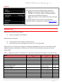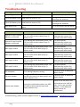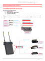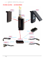
1
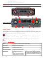
MCR41-MCR42 User Manual Single-Dual True Diversity Camera Receiver SN: ________________ rev.09 (rif. FW 2.0.4) Date: 11 July 2014 MCR41-MCR42 User Manual rev.09 1 rev.09 MCR41-MCR42 User Manual BRIEF DESCRIPTION MCR41/42 is a high performance microphone receiver suitable for broadcast and high professional applications. Thanks to Wisycom movable filter technology, MCR42 is able to work in a bandwidth up to 230 MHz, still keeping an exceptional selectivity and intermodulation immunity. This miniature design allows to integrate a DUAL TRUE DIVERSITY receiver while keeping a small size to fit camera slot in: Ikegami/Panasonic (UNISLOT™) Philips/Thomson/Grass Valley Sony The audio receiver block is fully digital to allow a better quality, digital output and emulation of most of companding chipsets. It supports also AES3 audio output with an overall sounds delay below 1.5 msec. MCR42 is designed to be: “easy & quick to use” thanks to automatic setup functions (i.e. frequencies, squelch, scan), remote configuration utilities (thru infrared), an OLED display with intuitive context menu navigation. “extremely flexible”, with an incredible frequency agility up to 230MHz. Moreover the DSP board allows analogue and digital (AES3) output, with multi-companding compatibilities and other digital features. “best in class performances”, thanks to the latest Wisycom technology the unit has extreme RF sensitivity and immunity and superb audio quality. “a durable & upgradable investment”, thanks to the very robust design (aluminum housing) and the possibility to upgrade/enhance units performances. Moreover MCR42 system is already set up for the exclusive PTT function (remote command), developed and patented by Wisycom and now appreciated in the broadcast world: Simply pushing this button (PTT), the presenter causes the remote switching of the receiver’s output-line, from the “main line” to the additional “intercom line”, in order to be able to talk “offair” directly with the technical team. Then all PTT’s MICs can be connected in pre-fading allowing a clever intercom setup. 2 MCR41-MCR42 User Manual rev.09 SAFETY INSTRUCTION Read this safety instruction and the manual first Follow all instructions and information. Do not lose this manual. Do not use this apparatus under the rain or near the water. Do not install the apparatus near heaters or in hot environments, do not use outside the operating temperature range. Do not open the apparatus, only qualified service technician are enabled to operate on it. The apparatus needs servicing when it is not properly working or is damaged by liquids, moisture or other objects are fallen in the apparatus. Use only accessories or replacement parts authorized or specified by the manufacturer. Clean the apparatus only with dry cloths, do not use liquids. Report the serial number and the purchasing date in front of the manual. It is needed to have proper replacement parts or accessories from the manufacturer. When replacement parts are needed, use only replacement parts authorized from the manufacturer. Substitution with not authorized parts could result in electric shock, hazards or fire. Keep attention on all the labels with warnings or hazards on the apparatus. WARNING: The apparatus is intended for professional use; anyway the manufacturer alerts the user that the headphone output power of the apparatus could exceed the level of 85 dB(A) of sound pressure level and this could be dangerous for the hearings. Do not use the headphone with high power level or for long time. Reduce the power or suspend the hearing in case of any kind of hearing problem. WARNING: when operating thru battery pack always replace ALL BATTERIES. DO NOT operate the device with some new and some old batteries. When MCR42 is setup to “automatically turn on”, DO CHANGE ALL OF USED BATTERIES after automatic low batteries shutdown. 3 rev.09 MCR41-MCR42 User Manual MAIN FEATURES MCR41/42(*) is a camera dual true diversity wireless-microphone receiver system in a modular stand-alone or slot-in configuration (compatible with most camera’s slot): Extreme RF (radiofrequency) performances and reliability Extreme frequency agility (tuning windows up to 240 MHz with independent tunable filters on 2 ch’s): MCR42-L: 470÷678 MHz MCR42-H:590÷822 MHz MCR42-N 470÷700 MHz MCR42-M: 566÷798 MHz (extended range up to 830 available on request and upon your country-specific regulations) digital output on AES3 multi-companding compatibility future digital functionality enhancements Automatic scan for best channels, squelch and other automatic setup Infrared interface (i.e. for system setup, microphone programming) Automatic transmitter re-programming (thru infrared, sync function) Push to Talk (PTT) function with additional audio output signals (patented) (*) Note MCR41 is the version with only one diversity RX board mounted. It supports all features of MCR42 and is compatible with MCR42 Firmware. It is also possible to mount the second Rx board to upgrade a MCR41 to an MCR42. Technical description The MCR42 is a professional dual true diversity receiver for wireless microphones reception especially designed for broadcast production, live stages, theatres and top professional applications. It’s winning performances are: High immunity on strong RF environment Huge switching bandwidth High audio performances and flexibility with analog or digital processors High reliability and durability One of the milestones in the design of the MCR42 is high reliability: most of the circuitry of the receiver is independent one from each other. 4 MCR41-MCR42 User Manual rev.09 Above a schematic with an overview of main receiver functions. For each antenna the RF signal is split in the receiver 1 and in the receiver 2 (antenna A and antenna B) with a wide band splitter. In this way any one receiver could be tuned in any frequency of the switching range (typ. 240 MHz). Receiver 1 and 2 are diversity receivers: each one is made of two receivers tuned on the same frequency, hereafter called section A and section B. The receiver 1 section A and the receiver 2 section A are connected to the antenna A, the receiver 1 section B and the receiver 2 section B are connected at the antenna B. Each receiver has its own demodulated signal and its own RSSI signal (Receiver Signal Strength Indication); a DSP selects or combines signals from section A & B to have the best audio. The demodulated signal flows to the digital audio processor. the data sub carrier is digitally filtered to a very selective equivalent bandwidth (3Hz). Each filter has its own data demodulator, one for medium speed data detection at the output of the first filter and one at low speed data detection at the output of the second filter. All the two demodulators are connected to the supervisor micro controller for the data battery detection and signalling. Digital audio processor: the demodulated signal is filtered by an anti aliasing low pass filter and then converted in the digital domain with a 96KHz 24bit audio A/D converter. The digital signal processor (DSP), working in double precision, replicates all the analog functions with very high accuracy, ultra low distortion and without typical analog problems like components tolerances or long term drifts or temperature drifts etc. The high speed audio algorithms implemented in assembler into the MCR42 maintains the audio delay at about 1.3 milliseconds, making it ideally for live events and to keep audio delay as short as possible. The DSP unit also filters and demodulates the data carrier and communicates all the parameters and informations to the supervisor micro controller. The audio output goes to the digital outputs (AES3) or is converted in the analog domain with a high quality 24 bits 96KHz D/A converter and an anti-aliasing filter. 5 rev.09 MCR41-MCR42 User Manual USER GUIDE A C C B NEW DISPLAY C D F G E Front Panel MCR42 allows an easy and quick configuration using buttons, RGB LED’s and an OLED display. The front panel is functionally divided in the following section: A&B SMA antenna Connector: MCR42 is supplied with a couple of antenna tuned on 400 MHz bandwidth suitable to be used with MCR42-L, MCR42-H, MCR42-N, MCR42-M, version. C RGB Leds: Each of the 2 receivers has a dedicated set of LED’s to give a clear indication of its status. “ON LED” (on NEW display) GREEN The receiver is on with an external power supply PALE GREEN The receiver is on with battery GREEN BLINKING The external power is low PALE GREEN BLINKING The power of the battery is low RED BLINKING Relative transmitter battery is low: - slowly blinking if 25% lifetime - quickly blinking if 12% lifetime 6 When the “ON LED” become red blinking, the display, if it is off, it automatically turns on and remains on until the alarm does not fall. MCR41-MCR42 User Manual rev.09 “ON LED” (on OLD display) OFF Relative receiver is not active GREEN Relative receiver is active and battery/external power is not low RED Relative receiver is active and battery/external power is low RED BLINKING Relative transmitter battery is low: - slowly blinking if 25% lifetime - quickly blinking if 12% lifetime “RF LED” OFF Relative receiver is not active RED RF level below squelch on both diversity receivers GREEN RF level above squelch and receiver A is active (ANTENNA A) BLUE RF level above squelch and receiver B is active (ANTENNA B) “AUDIO/AF LED” RED Audio muted due to RF squelch or tone squelch GREEN Audio active & tone squelch detected BLUE Audio active & tone squelch not detected D “MENU/SEL” BUTTON Push this button to navigate function menu’s and to confirm the chosen setup. F “PWR/EXIT” BUTTON Push and keep this button to power on/off the receiver. The on/off status is permanently memorized into the non-volatile memory, this way the system can be setup to automatically turn on Rx1, or Rx2, or both, when power up. During menu navigation push this button to exit from current menu (escape function). E “Arrow up/sync” BUTTON Push and keep this button to start a synchronization with a Wisycom transmitter (follow instructions on display). Before starting synchronization IRDA must be enabled on Wisycom transmitter. During menu navigation push this button to move -up and select the previous item. G “Arrow down/scan” BUTTON Push and keep this button to start the automatic scan. During menu navigation push this button to move-down and select the previous item. H “OLED Display” The receiver has a high contrast display. Pushing a button while the receiver is active, turn on automatically the display. After a time-out the display turns off automatically. 7 rev.09 MCR41-MCR42 User Manual Display menu Volume Headphones Rx Signal Power On RX1+RX2/ -23÷5dB (step 1 dB) RX1(L+R)/RX2(L+R)/RX1+RX2(L+R)/RX1(L);RX2(R)/RX1(R);RX2(L) LINE/TSQ>LINE /RX1 Only MCR42 (not MCR41) GR: 0÷39 Gr-Ch Only for Slot-in BPA42HPN CH: 0÷59 L: 470.000÷678.000 Frequency H: 590.000÷822.000 step 25kHz N: 470.000÷700.000 M: 566.000÷798.000 Squelch OFF- 0/3/6/9/12/15/18/21/24/28/32/36/40/46 dBµV Expander ENR Wis/ENC Wis... Tone Squelch OFF/ON/ADV MAIN Tone Squelch Edit RX1/RX2 Config OFF TSQ OFF c LINE c COM Config ON TSQ ON c LINE c COM Config ADV TSQ ADV PTT Rel . c LINE c COM PTT psh. c LINE c COM LINE max lev -8 ÷ +12 dBu (step 1dB) MIC max lev -30 ÷ -10 dBu (step 1dB) LINE max lev Audio out Sign. Phase -18 ÷ +12 dBu (step 1dB) AES3 max lev -30÷0 dBFS (step 1dB) COM max lev -18÷+12 dBu (step 1dB) Only for HW rev ≥ 21 Only for HW rev < 21 0°-180° Scan Cal. tone LINE mode Display Infrared OFF/ON 0dB/ON -18dB AES-3 / Analog LED Full / Alarm /OFF Contrast 0÷5 On Timeout (sec) 5÷60 (step 5 sec) Sync Info Preset 8 Power / Model / Serial / Range / Options / HW rev / BL / App / Base / Alim / Top / Display / Errors Restore 1/2/3/Factory Save 1/2/3 Only with BPA42-PTT Preset parameters MCR41-MCR42 User Manual rev.09 Using navigation buttons it is possible to quick & easy navigate through the MCR42 menu: - Sel/Exit to enter or exit a level - Arrow up/down to circle on the same level - To save the modified parameters press and hold the SEL /MENU button ( ) until appears the message "SAVED." MAIN MENU RF bar (8 steps of 10dBµV, from 10 to 80 dBµV) HEADPHONE (only for BPA42-HPN) Cycle through menu’s with up/down arrow to get your desired configuration then confirm with SEL. Volume: It is possible to set the desired output level from Max (+6 dB) to min (-24 dB) in 1 dB step. RX: Left and right channel of stereo jack can be mapped respectively on RX1, RX2 or on RX1+RX2. Signal: If set to LINE, on the headphones there is the same signal of the output LINE. If set to TSQ>LINE and the Tone Squelch is enable (Tone Squelch ON or ADV), on the headphones it is possible to hear the signal even when the Tone Squelch is not detected. POWER ON (only for MCR42, not MCR41) Allow to enable both the receivers: Only receiver 1 (Rx1), only receiver (Rx2) or (Rx1 + Rx2). 9 rev.09 MCR41-MCR42 User Manual EDIT RX1 (MCR42 has the same menu for Rx2) Selecting this sub-menu most of RX1 setups are configurable. EDIT RX1: GR-Ch Select current group and channel. Group name and channel frequency are displayed on the right. EDIT RX1: Frequency If the specific group/channel is not locked, then can be edited in this menu. EDIT RX1: Squelch This menu allows to disable the RF squelch (OFF) or to setup the desired squelch level in dBµV (note 0 dBµV is equal to -107 dBm). EDIT RX1: Expander MCR41/42 supports 2 systems” different type of “Companding ENR-Wisy: designed for maximum noise reduction ENC-Wisy: designed for maximum audio fidelity (use this in case of special vocal application or to remote instruments) MCR42 core is a power digital audio processor that, besides an unbeatable audio quality and flexibility, can emulate most companders systems on the market. On this menu you can setup the audio companding chipset emulation. ENR is emulating the Philips™ SA572 and PTT digital data of Wisycom transmitters. Other setups can be loaded on request. 10 MCR41-MCR42 User Manual rev.09 EDIT RX1: Tone Squelch MCR42 is able to detect a digital tone squelch generated by a Wisycom transmitters (ex. MTH400/MTH300/MTP40/ MTP30). Tone squelch ON: when the tone squelch is enabled the audio is muted unless the correct carrier is detected. Tone squelch allows to work with lower RF squelch, increasing the coverage and the robustness especially in presence of digital television carriers (DVB-T). Tone squelch ADVanced: when tone squelch is in advanced mode the receiver processes also PTT data (push to talk): activating the command audio output when the button is pressed on remote transmitter. When tone squelch is off it is possible to choose where to put the output between LINE and COM. The COM column is present only using the Stand alone socket BPA42-PTT When tone squelch is set to ON it is possible to choose where to put the output between LINE and COM. The COM column is present only using the Stand alone socket BPA42-PTT When tone squelch is in advanced mode it is possible to access a more complex audio matrix where to put the output between LINE and COM and between PTT rel. (released) and PTT psh (pushed) Usually Line is always ticked and Com (PTT) is ticked on “PTT push.” as additional return channel (intercom). The COM column is present only using the BPA42-PTT NOTE: With squelch and tone squelch the audio output is activate when: Squelch OFF Squelch = 0,3,6,… dBµV Tone squelch OFF Always Tone squelch ON If tone is detected RF level ≥ Squelch RF level ≥ Squelch & tone squelch is detected 11 rev.09 MCR41-MCR42 User Manual EDIT RX1: Audio Out In Audio Out it’s possible to set the nominal audio output. For MCR42 with Hardware version ≥ 21, the max audio level of the RX1/RX2 output can be set from -30dBu to -10 dBu (in the first selection appears “MIC max lev”) and from -8dBu to +12 dBu (in the first selection appears “LINE max lev”) For MCR42 with Hardware version < 21, the max audio level of the RX1/RX2 output can be set from -18dBu to -12 dBu (“LINE max lev”) The max audio level of the COM output can be set from 18 dBu to +12 dBu in one dB step. The max audio level of the AES3 output can be set from -30dBFS to 0 dBFS in one dB step. EDIT RX1: Sig. Phase To change audio phase of 0 deg or 180 deg. EDIT RX1: Scan This function can be called also using the dedicated scan button (push and keep). It allows to make a scan over a desired frequency group. MCR42 manages up to 2400 custom frequencies organized in 40 groups of 60 channels each. This extreme flexibility makes the scan function very flexible. Once started a scan operation the receiver asks for group to be used. Then it prompts to turn off all transmitters. Then finally start the scan! After few seconds, scan results are displayed on a chart. 12 MCR41-MCR42 User Manual rev.09 Results can be also displayed sorted by level (pushing together SYNC and SCAN buttons), making easier to pick up the best one. NOTE: As per Wisycom standard, group 00 and group 01 or 09 are special; respectively the “center frequency” (474,482/... MHz) and the intergap frequency (i.e. 470/478/486/... MHz). A scan on group 00 will reveal in few seconds the overall DVB-T occupation on the area, while a scan on group 0 or 09 will give possible working frequency, usable also in presence of strong DVB-T signal (sort to speak working in the band-guard of 2 digital television channel). EDIT RX1: Cal. tone If Cal. tone is enabled, a calibration tone is transmitted from the outputs. It’s possible to select the audio level between -18dB and 0 dB. LINE mode: In LINE mode is settable the type of output between analog and AES3 (digital). NOTE: When LINE mode is set to AES3 the digital output (Rx1+Rx2 in digital) is available on Rx1 output. Display: In this menu item it’s possible to set the mode of switch on of the front LEDs and the contrast and the timeout of the display. LEDs mode: - Full: all LEDs are activate as indicated on -USER GUIDE - Front Panel - Alarm: the LEDs are ON only in case of alarm ----------(only red) - OFF: all LEDs are always off Infrared: By activating the infrared, you can connect the MCR42 to other devices (such as a UPK300) 13 rev.09 MCR41-MCR42 User Manual Sync: With the MCR41/42 you can synchronize your device with others via the sync function. After the selection of the desiderate receiver that you want to synchronize (RX1 or RX2 for MCR42), pull the infrared sensors of the 2 devices and wait for it to synchronize. At the end of this operation the 2 devices will be synchronized to the same frequency. INFO In the info menu the following information are displayed: Info description Power: MCR42 dual rx / MCR41 Model: The serial number composed by 1 letter+7 numbers Serial: Frequency range according to the MCR band: Range: Option: BL: HW rev: App: Base: Alim: Top: Display: Errors: 14 L: 470-678 H: 590-822 N: 470-700 M: 566-798 For this product the option specific the band (L/H/N/M) Bootloader version Hardware version Application version Version of rear panel: BPA42-PTT BPA42-HPN S1LK 42-SX SLK 42-IK SLK 42-PH Type of power supply Indicates if there is mounted a Top Feed and the type 0 if there is an old display / 1 if there is a new display Number of errors. If the number of errors is > 0 push SEL button to enter on the Errors list. For each error a brief description and the error code is showed. For more information, please see the Error List section. example 12.0Volt MCR42 dual rx S3536539 470-678 L v1.0.15 21 V2.0.4 BPA42-PTT Ext EL2 1 2 MCR41-MCR42 User Manual rev.09 PRESET: The preset menu has the following two submenus: Restore: that allows to reload 3 different presets (named 1, 2, 3) earlier saved or a Factory preset (a preset load in the Wisycom factory) Save: that allows to save 3 different presets (named 1, 2, 3) Each saved preset consists of all user parameters indicated in blue in the graphic on page 8 (Display menu). ERROR LIST When an error occurs, the receiver A. shows a message on the display and for some error types B. C. increases the errors counter in the info menu inserts the error type and code on the error list in the info menu When the error is solved, the message on the display disappear, but the error information (code and description) are available on the error list in the Info menu (only for some error, see the below table). NOTE1: When the receiver is reset the error information (code and error type on the list) are lost. Errors Low voltage level TX of RX1 Battery Low TX of RX2 Battery Low Rear panel error Device ID copy1 invalid, Memory recovered Device ID copy2 invalid Memory recovered RX1 copy1 invalid RX1 copy2 invalid RX2 copy1 invalid RX2 copy2 invalid PLL unlocked CH mem header Param mem header Message on display (A) Battery Low / Ext pwr Low TX1 Pwr Low TX2 Pwr Low BASE: Error - Error type (C) Code (C) MB mem copy 1 87 MB mem copy 2 88 RX1 mem copy 1 RX1 mem copy 2 RX2 mem copy 1 RX2 mem copy 2 PLL unlocked CH mem header Param mem header 89 8A 89 8A 84 85 86 15 rev.09 MCR41-MCR42 User Manual Troubleshooting Warning Low voltage level Warning description Low voltage level TX of RX1 Battery Low Low batteries level on TX1 TX of RX2 Battery Low Low batteries level on TX2 Rear panel error Alarms Device ID copy1 invalid Memory recovered Device ID copy2 invalid Memory recovered RX1 copy1 invalid RX1 copy2 invalid RX2 copy1 invalid RX2 copy2 invalid The receiver doesn’t recognize the rear panel Alarm description Error during the initialization phase. The CRC-16 check of device data (copy 1) detects error. Error during the initialization phase. The CRC-16 check of device data (copy 2) detects error. Error during the initialization phase. The CRC-16 check of RX1 data (copy 1) detects error. Error during the initialization phase. The CRC-16 check of RX1 data (copy 2) detects error. Error during the initialization phase. The CRC-16 check of RX2 data (copy 1) detects error. Error during the initialization phase. The CRC-16 check of RX2 data (copy 2) detects error. throubleshooting Replace battery or power supply - change batteries - recharge the batteries - change batteries - recharge the batteries -Try to reconnect the rear panel throubleshooting - no (the receiver automatically replace the corrupt copy1 with copy2) - no (the receiver automatically replace the corrupt copy2 with copy1) - no (the receiver automatically replace the corrupt copy1 with copy2) - no (the receiver automatically replace the corrupt copy2 with copy1) - no (the receiver automatically replace the corrupt copy1 with copy2) - no (the receiver automatically replace the corrupt copy2 with copy1) - send to repair at Wisycom Repair Centre PLL unlocked Error during frequency tuning CH mem header During the MTK952 initialization phase, the CRC-16 check of RF data (copy1 and copy2) detects error - send to repair at Wisycom Repair Centre During the initialization phase, the CRC16 check of device data (copy1 and copy2) detects error Check in the info menu the Serial take on the ‘UNCAL’ vale. In this case send the receiver to the Wisycom Repair Centre for recalibration. Param mem header If a problem not listed in the above table occurs or if the problem cannot solved with the proposed troubleshooting, please contact support service at [email protected] or [email protected]. 16 MCR41-MCR42 User Manual rev.09 ACCESSORIES AND PARTS TOP FEED OPTIONS & SLOT IN MCR42 has 4 main audio sources: Audio Line 1&2 AES3 (audio 1&2, 48kHz 24bit) PTT (push to talk) 1&2 Headphone (left/right) Top feed can bring on top on a mini-XLR 5M connector two balanced audio called line1 and line2. MCR42-Exx can then be in factory configure to connect on top (line 1 & 2) the audio source you need. MCR42-EL2: Audio Line 1 & 2 CAM50-3 CAM50-41 Line 1 & 2 to XLR MCR42-EC2: PTT Line 1 & 2 Line 1 to XLR MCR42-ELC: Audio Line 1 & PTT Line 2 MCR42-ECL: PTT Line 1 & Audio Line 2 CAM50-42 Line 2 to XLR MCR42-Exx IKEGAMI/PANASONIC SLK42-IK SLOT-IN KIT GRASS VALLEY SLK42-PH SONY SLK42-SX 17 rev.09 MCR41-MCR42 User Manual STAND-ALONE - ACCESSORIES BCA42 FLA42 MCR42 Back Panel Batt. pack 5AA Headphone BPA42-HPN CDC34 CAM50-2 Power (Hirose) BPA42-PTT CAM50-3 18 PTT out 1 & 2 Line out 2 Line out 1 / AES3 CAM50-2 MCR41-MCR42 User Manual rev.09 REAR PANEL The standalone socket BPA42-PTT and BPA42-HPN supply the following connections. BPA42-PTT: Stand alone socket BPA42-HPN: Stand alone socket Line 2 Line 1 AES3 (Line 1 & 2) Power Headphone COM pin: 1) GND 2) COM1+ 3) COM14) COM2+ 5) COM2- DC pin: 4) +Vdc 1) GND Analogue Audio Output (Line 1 & 2) • Audio line-output 1 & 2 : electronically balanced on two 3 pin mini-XLR Female connector • Audio line-output level : Adjustable in a one dB step between -20 and +6 dBu (nominal) and MAX +12 dBu (peak deviation) • Audio line-output imped. : ≤ 200 ohm. Digital Audio Output AES3 • Digital line-output 1 & 2 : electronically balanced on 3 pin mini-XLR Male connector • Digital line-output : AES3 @ 48 kHz DC power supply (connector Hirose HR10A-F) • pin 1 = ground • pin 4 = +Vdc Push to Talk (PTT) Audio Output (Com) • PTT line-output 1 & 2 : electronically balanced on a 5 pin mini-XLR Male connector Headphone output • output on stereo 3.5 mm headphone adapter (with locking) With the standalone socket BPA42-PTT and BPA42-HPN is available the option OP-BPA42-R22 to have an attenuation of -22dB in Line 1 and Line 2 outputs. NOTE: With this option, it’s not possible to use the AES3 output in the standalone socket and it’s not guaranteed the correct functionality of the AES3 output in the top feed. Option indicated in the label Although phantom power is defined over a parallel resistance of 6k8, some mixer without transformer are using very high capacitor without any limiting (or just some Ohm) impedance. That can cause a surge current on BPA42-PTT/BPA42-HPN voltage protection. TO AVOID ANY PROBLEM CONNECT THE DEVICE WITH MIXER TURNED OFF. 19 rev.09 MCR41-MCR42 User Manual SLOT IN SOCKETS To transform MCR42 in slot-in compatible for a specific camera you need to use a kit with a rear panel and a flange. Under the item BASE of the submenu INFO you can see the type of rear panel SLK42-IK for - IKEGAMI - Panasonic SLK42-PH for - Philips - Grass Valley - Thomson S1LK42-SX - Sony TOP FEED COMPATIBILITY MCR42/41EL2 ELC ECL EC2 BPA42-PTT X X X X BPA42-HPN X SLK42-IK X Y Y Y X: for all firmware versions Y: only for firmware versions > 1.0.75 (Factory preset) 20 SLK42-PH X Y Y Y SLK42-SX X Y Y Y MCR41-MCR42 User Manual rev.09 CABLES CAM50-2 / CAM120-2 AF cable (50 / 120 cm), mini XLR-3F / XLR-3M connectors CAM50-3 AF cable (50 cm), mini XLR-5F / 2 XLR3Mconnectors CAM50-41 AF cable (50 cm), mini XLR-5F / 1 XLR-3M connectors Line 1 feed XL3-M (TO BE USED FOR AES3 CAMERA INPUT) CAM50-42 AF cable (50 cm), mini XLR-5F / 1 XLR-3M connectors Line 2 feed XL3-M (TO BE USED FOR AES3 CAMERA INPUT) CAP51-IK STAND ALONE HARNESS CABLE - DB25 (to MCR41) - 1 XLR-3M (isolated with audio tranformer) + hirose (to camera) CAP52-IK STAND ALONE HARNESS CABLE - DB25 (to MCR42) - 2 XLR-3M (line output isolated with audio tranformer) + hirose (power from camera) CAP51-SX STAND ALONE HARNESS CABLE - DB15 (to MCR41) -1 XLR-3M (line output isolated with audio tranformer) + hirose (power from camera) CAP52-SX STAND ALONE HARNESS CABLE - DB15 (to MCR42) - 2 XLR-3M (line output isolated with audio tranformer) + hirose (power from camera) CDC34 External power feeding cable, hirose/raw wires (50 cm) CAM50-2-TFR AF cable (40cm), mini XLR-3F / XLR-3M (line output isolated with audio tranformer) 21 rev.09 MCR41-MCR42 User Manual “Stand-alone" KIT BPA42-K "Stand-alone" KIT for MCR42 BPA42PTT + 2 x CAM 50-2 + CDC34 NOTE: to be used with proper back-panel (i.e. FLA42 or FLA42-SX) ANTENNAS AWN42RA Whip Antenna plastic case 90 deg sma connector Broadband UHF 470-700 MHz (black cap + 590 label) AWM42RA Whip Antenna plastic case 90 deg sma connector Broadband UHF 566-798 MHz (yellow cap + 670 label) AWN42 Whip Antenna plastic case sma connector Broadband UHF 470-700 MHz (black cap + 590 label) AWM42 Whip Antenna plastic case sma connector Broadband UHF 566-798 MHz (yellow cap + 670 label) AWL42 Whip Antenna plastic case sma connector Broadband UHF 470-700 MHz (black cap) AWH42 Whip Antenna plastic case sma connector Broadband UHF 590-822 MHz (yellow cap) AWF42 (discontinued) Whip Antenna plastic case sma connector Broadband UHF 470-822 MHz AWS42 (discontinued) Swivel antenna sma connector Broadband 470-822 MHz 90 deg bendable for desktop application 22 MCR41-MCR42 User Manual rev.09 OTHERS UPK300E Infrared programming kit (interface + software) USB interface BCA42 Battery power supply module (5 x 1.5V AA) - Batteries included NOTE: BPA42-PTT (or -HPN) must be installed FLA42 Screw-disassemble back-panel For camera-hardware mounting (not drilled) FLA42-SX Screw-disassemble back-panel For camera-hardware mounting (for Sony cameras) BCL42 Belt clip factory mounted on FLA42 VAP42 Carrying case for MCR41/42 Eng Systems. MCRMNT CAMERA SHOE MOUNT for MCR41/MCR42 23 rev.09 MCR41-MCR42 User Manual Stand Alone Mounting MCR42: Line1 is configured to AES3 output (audio 1 & 2) and PTT - CAM50-2: Line 1 (digital audio 1&2) connected to XLR-3F AES3 (digital input of the camera) - CAM50-3: PTT 1&2 connected to 2 XLR-3F intercom/audio inputs of the camera - CD34: connected to camera power source (if not using the battery pack) MCR42: Line1&2 are configured to analogue output and PTT - CAM50-2: Line1 (audio 1) connected to XLR-3F (analogue input of the camera) - CAM50-2: Line2 (audio 2) connected to XLR-3F (analogue input of the camera - CAM50-3: PTT 1&2 connected to 2 XLR-3F intercom/audio inputs of the camera - CD34: connected to camera power source (if not using the battery pack) 24 MCR41-MCR42 User Manual rev.09 Slot-in Mounting MCR42: Analogue Audio 1 & 2 audio thru internal slot in Check if your camera is supporting double internal audio! MCR42-EL2 or MCR42-ELC: Digital Audio 1 & 2 thru external AES3 camera input (XLR3F) - CAM50-41: Top feed Line 1 (digital audio 1&2) connected to XLR-3F AES3 (digital input of the camera) MCR42-EL2 or MCR42-ECL: Analogue Audio 1 thru slot in and Audio 2 thru external (XLR-3F) - CAM50-42: Top feed Line (analogue audio 1) connected to XLR-3F (2° analogue external input of the camera) Note: Using CAM50-41 or CAM50-42 or CAM50-3 it is possible to connect also additional PTT outputs to use your microphones as intercom to your camera-man or your control-room. MCR42 with the stand alone socket BPA42-HPN can support also top headphone output for special applications or standalone usage. 25 rev.09 MCR41-MCR42 User Manual HOW TO USE WISYCOM MCR42 UPDATER Wisycom MCR42 Updater can be used to: Upgrade firmware Change the name of the receivers RX1 and RX2 Modify/load/save the channels memory Instruction to connect MCR42 and UPK300E: 1. 2. 3. 4. 5. 6. 26 Connect to the PC the infrared programming interface (UPK300E) using a USB cable (NOTE: it is not possible to use IR interface of MRK950 or MRK960) Check if the version of Wisycom MCR42 Updater installed in your PC is the latest version. If not, uninstall the Wisycom MCR42 Updater actives in your PC and install the new version as indicated in the section How to install Wisycom MCR42 Updater. Run Wisycom MCR42 Updater Power up the receiver MCR42 and enable the IRDA interface: a. push button, b. push button until that Infrared submenu appears on the display (Power on>Edit RX1>Edit RX2>LINE mode>Display>Infrared) c. push again button and check the display shows ‘IR IF active’ put in contact MCR42 and UPK300E Push Connect button present in the under part of Wisycom MRC42 Updater panel and verify the information version of MCR41-MCR42 User Manual rev.09 How change the name of receivers Insert the name on the Name box presents in the MCR42 panel and push the Write button underlying. device How to read/ modify/ load/write/clear channels memory Push channels memory button 27 rev.09 MCR41-MCR42 User Manual Read: Push the button Read channels memory: this operation permits to read the channels memory in the MCR42 and show it in the central grid. Modify: After a Read operation, in the center grid it is possible to modify: - for the group: the locked/hidden propriety for the channel: the frequency value and the locked/hidden propriety (click right mouse button) NOTE: The modifications are applied only to the local channels configuration. In order to save them in the MCR42 it is necessary to do a Write operation or click right mouse button (write to device) Load: Push the button Memory view or select the File>Open menu and select the .wdf file to load. This operation loads the channels configuration in the central grid (local). In order to load the channels configuration in the MCR42, after a Load operation, it is necessary to do a Write operation. Write: Push the button Write channels memory: this operation writes the channels configuration showed in the central grid to the channels memory of the MCR42. Clear: Select the Channels memory menu and select Clear. This operation clears only the channels memory showed in the grid (local). In order to clear the channels memory in the MCR42, after a Clear operation, it is necessary to do a Write operation. Save: Select the File>Save menu and decide the name of .wdf to save. This operation create a .wdf file using the channels configuration showed in the central grid, it doesn’t save the configuration in the MCR42. NOTE 1: Read and Write operation require around 1 minute. NOTE 2: For small changes of channels memory, it is possible to select only the modified cells and write only the changes. In this case only the selected channel/group are written to the MCR42 and the writing process is more fast. NOTE 3: For MCR41 only one receiver is showed and can be configured. For more information or support, download the user manual of MCR41/42 at the following link http://www.wisycom.com/www3/products/product/mcr42#4 or email us at [email protected] 28 MCR41-MCR42 User Manual rev.09 TECHNICAL SPECIFICATION • Frequency ranges [1] : MCR42 L ⇒ option 470 ÷ 678 MHz MCR42 H ⇒ option 590 ÷ 822 MHz MCR42 N ⇒ option 470 ÷ 700 MHz MCR42 M ⇒ option 566 ÷ 798 MHz • Switchable channels : 40 groups of 60 channels fully user progr. • Switching-window : Up 240 MHz [1]. • Frequencies : Microprocessor controlled frequency synthesizer circuit, with 25 kHz minimum step. The frequencies is easily PC reprogrammed with the optional UPK 300E Programming Kit. • Frequency error : < ± 2.5 ppm, in the rated temperature range •Temperature range : -10 ÷ +55 °C • Modulation : FM, with 50 μs de-emphasis. • Nominal deviation : ±40 kHz (Max. operating dev. = ± 60 kHz). • “A” / “B” antenna inputs : With sturdy connectors. • Antenna input impedance : 50 ohm sma type (SWR < 1:2; typ. 1:1.4). • Sensitivity : ⇒ 2 μV ( 0 dBμV), for SND/N > 58 dB; ⇒ 5 μV (14 dBμV), for SND/N > 98 dB. in the whole switching-window [2]. • Amplitude response : < 0.5 dB (RF input sig.:6 dBμV ÷ 100 dBμV). • Co-channel rejection : > 2.5 dB. • Adjacent chan. selectivity : > 80 dB typical (for ch. spacing ≥ 400 kHz). • Spurious rec. rejection : > 100 dB. • IF image rejection : > 90 dB. • Intermod. rejection : > 76 dB. • IIP3 : > +10 dBm typical. • Spurious emissions : < 2 nW (typical = 0.1 pW). • Noise Reduction system : ENR (Wisycom Extended-NR) , noise optimized ENC (Wisycom Extended-NC), voice optimized & with reduced pre-emphasis ⇒ Others, compatible with most systems, thru an internal DSP emulation of SA572, SA575 and Rms envelope compander chip set, fully user programmable • AF bandwidth : 30 Hz ÷ 20 kHz. • Frequency response : ± 0.5 dB in the 30 Hz ÷ 19 kHz range. • Distortion : 0.3 % typical. • SND/D ratio (Analogue) : 110 dB typical [2] • SND/D ratio (AES3) : >125 dB typical [2] • POWER LEDs : 2 multicolour RGB LEDs to easy indicate Rx1 & Rx2 power status: - GREEN, if "Receiver ON" with external power supply; - RED, if Empty battery/power supply; LEDs blinking indicates power supply status of transmitter: 29 rev.09 MCR41-MCR42 User Manual - slow blinking, at 25% battery capacity; - fast blinking, at 12.5% battery capacity. • POWER LEDs (new display) : 1 multicolour RGB LEDs to easy indicate Rx1 & Rx2 power status: - GREEN/PALE GREEN if "Receivers ON" with external power supply/battery; - GREEN blinking/PALE GREEN blinking if low power supply/ low battery level - RED blinking indicates power supply status of transmitter: slow blinking, at 25% battery capacity; fast blinking, at 12.5% battery capacity. • RF LEDs : 2 multicolour RGB LEDs to easy indicates Rx1 & Rx2 RF status. Always on in normal operation: - RED, if both receivers RF level is under squelch level; - GREEN, if signal above squelch level & antenna A (green) is active; - BLUE, if signal above squelch level & antenna B (blue) is active; - YELLOW, if signal above squelch and both antenna are used. • AUDIO LEDs : 2 multicolour RGB LEDs to easy indicates Rx1 & Rx2 audio status: - RED, if audio is muted cause of squelch (or tone squelch if active); - GREEN, if audio is active and tone squelch present; - BLUE, if audio is active and tone squelch not present. • Front buttons : Simple operation with 4 buttons to quickly monitor and setup the receiver. One touch function for a frequency scan and sync function. • Powering : - External = 5 ÷ 18 Vdc (1.5 W max). - Autonomous. = with optional BCA 42 Battery Module (5 x IEC-LR6 1.5V size-AA alkaline or rechargeable elements). • Dimensions : “Slot-in” execution= 68 x 18 x 115 mm, “Stand-alone” exec.= 68 x 18 x 135 mm. • Weight : 180 g approx. : : : Electronically balanced on two 3 pin mini-XLR Female connector Adjustable in a one dB step between: -20 and +6 dBu (nominal) and MAX +12 dBu (peak deviation) ≤ 200 ohm. Analogue Audio Output • Audio line-output 1 & 2 • Audio line-output level • Audio line-output imped. Push to Talk (PTT) Audio Output • PTT line-output 1 & 2 : Electronically balanced on a 5 pin mini-XLR Male connector Digital Audio Output • Digital line-output 1 & 2 • Digital line-output : Electronically balanced on 3 pin mini-XLR Male connector : AES3 @ 48 kHz NOTE [1]: Extended limits or other custom ranges are available on request, if allowed by your country-specific regulation. NOTE [2]: RMS value, 22 Hz / 22 kHz, unweight. The MCR 42 receiver complies with ETSI specifications: ETS 300 422. 30 MCR41-MCR42 User Manual rev.09 WISYCOM srl Via Spin 156 I-36060 Romano d’Ezzelino Italy Tel. +39 -0424 -382605 Fax +39 - 0424 - 382733 www.wisycom.com e-mail: [email protected] 31 rev.09 MCR41-MCR42 User Manual ITALY ONLY Obblighi di informazione agli utilizzatori Modello di informazioni agli utenti dei prodotti di tipo “professionale” INFORMAZIONE AGLI UTENTI ai sensi dell’art. 13 del Decreto Legislativo 25 luglio 2005, n. 151 “Attuazione delle Direttive 2002/95/CE, 2002/96/CE e 2003/108/CE, relative alla riduzione dell’uso di sostanze pericolose nelle apparecchiature elettriche ed elettroniche, nonché allo smaltimento dei rifiuti” Il simbolo del cassonetto barrato riportato sull’apparecchiatura o sulla sua confezione indica che il prodotto alla fine della propria vita utile deve essere raccolto separatamente dagli altri rifiuti. La raccolta differenziata della presente apparecchiatura giunta a fine vita e’ organizzata e gestita dal produttore. L’utente che vorrà disfarsi della presente apparecchiatura dovrà quindi contattare il produttore e seguire il sistema che questo ha adottato per consentire la raccolta separata dell’apparecchiatura giunta a fine vita. L’adeguata raccolta differenziata per l’avvio successivo dell’apparecchiatura dismessa al riciclaggio, al trattamento e allo smaltimento ambientalmente compatibile contribuisce ad evitare possibili effetti negativi sull’ambiente e sulla salute e favorisce il reimpiego e/o riciclo dei materiali di cui è composta l’apparecchiatura. Lo smaltimento abusivo del prodotto da parte del detentore comporta l’applicazione delle sanzioni amministrative previste dalla normativa vigente. 32 MCR41-MCR42 User Manual rev.09 33 rev.09 34 MCR41-MCR42 User Manual MCR41-MCR42 User Manual rev.09 Wireless System Communications Via Spin 156 I-36060 Romano d’Ezzelino Italy Tel. +39 -0424 -382605 Fax +39 - 0424 - 382733 www.wisycom.com e-mail: [email protected] 35