1
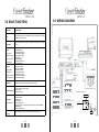
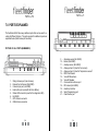
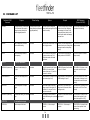
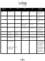
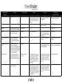
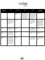
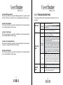
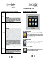
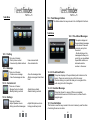
User’s Manual
Australia: 1300 1 fleet (35338)
Outside Australia: +61 8 9383 7833
Website: www.fleetminder.com.au
Tracking URL: http://tracking.fleetminder.com.au/fleetfinder
User’s Manual
TABLE OF CONTENTS
1.0
Introduction
22
2.0
Packaging Contents
33
3.0
Precautions
33
4.0
Operating Requirements
66
5.0
Basic Functions
89
6.0
Wiring Diagram
910
7.0
Ports
Explained
Port Explain
10
8.0
Accessories
1213
9.0
SMS Setup
1314
10.0
GPRS Online Tracking
21
11.0
Troubleshooting
24
12.0
Screen Functions
2526
13.0
Technical Data
2930
14.0
Warranty Information
3132
11
22
24
P1
2.0 PACKAGING CONTENTS
1.0 INTRODUCTION
Congratulations on your purchase of fleetfinder Gold!
fleetfinder GOLD is an exciting Australian designed product that
enables you to personally take control of the security and tracking of
your assets.
The fleetfinder GOLD system works independently, but has Inputs and
Outputs, which means it can be connected to any existing alarm
system for alarm notification or additional triggers. The Inputs and
Outputs can be configured to control a range of different features. The
fleetfinder GOLD has a variety of different ways of reporting an event,
or reporting to a command. The fleetfinder GOLD is fitted with a GSM/
GPRS module that allows for GPRS and SMS reporting.
Before commencing installation please make sure all components listed
here are accounted for. In the packaging you should have.
•
•
•
•
•
•
•
•
1 x fleetfinder Gold unit -1
1 x GPS / GSM antenna -2
1 x fleetfinder GOLD Screen -3
1 x Screen interface cable -4
1 x Wiring harness -5
1 x Screen stand + mount -6
1 x Screen charger -7
1 x owner’s manual -8
2
4
When using GPRS, the fleetfinder GOLD will log data on our tracking
website, for easy reviewing by fleet managers, or owners. The fleetminder GOLD reporting can be set to many different intervals, for
tracking accuracy. For SMS reporting, the fleetfinder GOLD, can either
report the co-ordinates to the tracking website, or can report a link for a
map, that can be viewed on any GPRS mobile phone.
Unlike other tracking products on the market, fleetfinder GOLD use
by SMS does not require a subscription to a base monitoring service
for basic functions. However, in most cases, we recommend that fleet
managers subscribe to our web service. The vehicle history is available
in a range of formats online and retrievable at any time via our optional
subscription service.
NOTE: For the full features of the online tracking feature, please
refer the Online tracking manual.
P2
•
•
•
•
•
•
•
7
6
3
1
5
1 x Help switch -9
1 x Diagnostic LED -10
1 x Temp sensor cable -11
1 x Fuel sensor cable -12
1 x RFID scanner -13
2 x RFID cards -14
1 x Backup battery -15
15 11 12
13
14
Optional accessories can be supplied on request
.
3.0 PRECAUTIONS
IMPORTANT:
Make all wiring connections to the vehicle and antenna connections to the
correct sockets BEFORE connecting the main plug to fleetfinder GOLD.
(Refer to the step by step Installation manual)
P3
It is strongly recommended that the units SIM card is first registered,
contains credit and is tested before installation is commenced. Testing
will require a valid SIM service. For GPRS online tracking, the SIM card
MUST be GPRS enabled. When installing the GPS antenna, make sure
that the coaxial cable does not get bent or crimped.
Always keep fleetFinder’s phone number confidential and account paid
up for pre-paid services.
Remember your fleetfinders PIN & phone number, no one else should
know them. For Online tracking, please ensure that the SIM Card is GPRS
enabled (For more information on this please contact your SIM car service
provider)
Outputs are NOT recommended for use to directly or indirectly immobilize
an operating vehicle. Immobilizing a vehicle in motion is extremely
dangerous. The general purpose outputs are to be used to disable the
vehicle’s starter motor only.
This device is not to be used for unautorised monitoring or tracking.
Do not operate this device where mobile phones or radio transmitters are
not permitted. Do not operate on aircraftd. Do not operate near sensitive
electronics such as engine, brake or air-bag systems.
Electrical safety:
Designed to work from 12 volt or 24 volt DC only. Use 5 amp inline fuse.
Explosive Atmosphere:
The fleetminder GOLD uses the GSM network, and it is not advisable to
request tracking during refuelling, at blast sites or at chemical
sites etc.
Aircraft safety:
When transporting this equipment by air, ensure the unit is totally
disabled, by removing the SIM card from the SIM card slot. And ensuring
the Red power LED is switched off. (If the Red LED is flashing, press
and hold reset button for 4 seconds, until all lights switch off.)
Other Precautions:
Outputs:
- The outputs are rated at 300mA max.
- As default the outputs are set to trigger a low. (ground)
- Due to outputs being limited to current, we recommend using a Relay
for outputs.
- The ouputs can be configured for a latch (permanent switch) circuit, a
pulse (800mS pulse) circuit (normally used for central locking circuits)
or cycle circuit (normally used for flashing indicators)
NOTE: Cycle will only last for 30 seconds.
- The outputs are most commonly used for Unlocking doors, Sounding
horn and disabling starter motor, but can be used for almost anything.
Inputs:
- The inputs can be connected to almost any electronic circuit, however
please note that there are 2 positive triggers (+12V or +24V) inputs,
and 1 negative trigger (GND) input.
Refer to the Installation manual for more information.
Medical Equipment:
Some medical devices such as pacemakers may be inhibited by
GSM signals. Check with a doctor or medical equipment
manufacturers for more advice on this issue.
P4
P5
4.0 OPERATING REQUIREMENTS
Environment
Do not install fleetfinder GOLD in direct sunlight or directly under
any areas exposed to direct sunlight or extreme heat. fleetfinder
GOLD incorporates sensitive electronics and is to be installed in
the vehicles cabin only.
Keep the unit installed in a secure location that is to be free of
dust, and moisture. For a stealth install it is recommended that the
fleetfinder GOLDis kept away from any radio antennas or speakers, as it may indicate that there is a GSM network
connection present to the vehicle operator.
Power
fleetfinder GOLD operates on a 12 volt or 24 volt supply only. If
fleetfinder GOLD has a voltage higher than the operating voltage
applied then the device will fail to operate and could cause internal
damage to the unit. If the power supplied is below the minimum to
operate, the unit will send a warning, if programmed to do so, and
may switch to backup battery power.
See fleetfinder GOLD specifications.
The built in backup power supply allows fleetfinder GOLD to
continue to operate and alert you if your vehicles battery power
is severed. The backup battery is float charged by your vehicles
electrical system.
GPS antenna location
fleetfinder GOLD is able to determine the exact location of your
vehicle by the use of the incorporated GPS receiver. For the GPS
to work most effectively, the external GPS antenna must be located
in a position with as much view of the sky as possible. The GPS
Antenna will generally operate through non metallic objects. Some
suggestions include high up under the dash and below the rear
parcel shelf. The black face of the antenna is the side which must
face skyward. Ensure before completing the installation that the
antenna is secured firmly in place.
Before picking a location in your vehicle for the GPS antenna, it is
best to first connect the GPS antenna to the fleetfinder GOLD and
apply power. Shortly after powering on fleetfinder GOLD you will
observe the green satellite LED on the unit turn on, this means the
unit is receiving GPS data.
If this does not happen, place the antenna on the roof of your vehicle, making sure that your vehicle is outdoors. Wait until the LED
comes on and stays on. This now indicates fleetfinder GOLD has a
fix on your vehicles location. Please be patient as with a cold start
(first power up) this process of satellite acquisition can take up to
5 minutes (in worst case). In some cases where the control of the
fleetfinder GOLD is set to SMS as a default, and the unit has
started up successfully (RED and GREEN lights on, with the
YELLOW LED flashing or still) you are able to find out the GPS
status by simply sending a “SYS” sms command from the Primary
declared phone number (see command list to see how to set this,
and for further instructions on the
SYS command).
In the reply message you will see the status of the GPS.
P6
P7
5.0 BASIC FUNCTIONS
FUNCTIONS
APPLICATIONS
GPS
GPS receiver will output a complete position, velocity, and time (PVT) solution in
the NMEA Version 3.0 protocol
GPRS, SMS
5 inputs
(most common
applications include
ACC, Alarm trigger,
and door trigger)
6.0 WIRING DIAGRAM
AD2 INPUT
GPRS uses standard TCP or UDP communication protocol. SMS can be turned
on or off.
AD1 INPUT
COIL (FOR ID CARD READER)
3 controllable inputs,
INPUT1 (positive trigger)
INPUT2 (negative trigger)
INPUT3 (positive trigger)
2 reserved inputs
Help switch trigger
Temperature switch port
AUX analogue input
OPTIONAL MIC
OPTIONAL SPEAKER
7 outputs
1. Gray wire (-300mA)
2. Green wire (-300mA)
(usually used for
3. Blue wire (-300mA)
4.
Orange wire (-300mA)
flashing lights,
5. Purple wire (-300mA)
disabling starter motor, 6. White/Red wire (-300mA)
and unlocking doors) 7. Brown/Yellow (-300mA)
Help Switch
Will send a report when the Help switch has been activated
Standard Reporting
Automatic report for tracking purpose:
Fixed time report
Fixed distance report
Event Report
(SMS, and GPRS)
History data store
(hardware)
Temperature report
Speeding report
Low battery report
Geo-fence trigger report
Input trigger report, e.g. ALARM, ARM, ACC inputs, etc (fully customizable) …
Intelligent report
G Force exceeded report.
GSM ANT
GPS ANT
OPTIONAL G SENSOR
LED
PANIC BUTTON
OPTIONAL CAMERA
Brown/Yellow - 300mA Output 7
12V or 24V
BATTERY
Pulse
Latch Cycle
White/Red - 300mA Output 6
Purple - 300mA Output 5
Pulse
Pulse Latch
Latch Cycle
Cycle
Pulse
Green - 300mA Output 2
Pulse
Latch
Latch
fleetfinder GOLD Navigation Screen
Cycle
Brown Input 2 - Trigger (GND)
Starter Motor Kill using fleetfinder GOLD
NOT CONNECTED
Cycle
Blue - 300mA Output 3
Pulse
Pulse Latch
Latch Cycle
Cycle
Orange - 300mA Output 4
Pulse
Latch Cycle
White Input 3 Trigger +12/24V
Gray - 300mA Output 1
87
(STARTER MOTOR KILL THROUGH RELAY)
Grey Wire from fleetfinder GOLD
Pulse
Latch
Cycle
Yellow Ignition Trigger +12V/24V
Green
86
87a
85
Orange
30
Cut Wire
IGN Switch
3,000 reports can be saved in unit, and read by the server at any time.
P8
STARTER
P9
7.0 PORTS EXPLAINED
9 10 11 12 13 14
The fleetfinder GOLD has many additional ports that can be used for a
variety of different funtions. The ports required for additional inputs are
explained below (Refer below port locations):
15
PICTURE OF ALL PORTS (NUMBERED)
1
1
2
3
4
5
6
7
8
-
2
3 456 7
8
Wiring Harness port (main harness)
Remote Control Sensor (Not USED)
Camera Input port (not USED)
Help button port (used with the Panic Button)
Status LED connection (used for the diagnostic LED)
Not USED
GPS Antenna connector
GSM Antenna connector
P10
9
10
11
12
13
14
15
16
17
18
19
20
21
16
-
17
18
19
20
21
Odometer sensor (Not USED)
Buzzer (Not USED)
Auxiliary sensor (Not USED)
Analogue Input 2 (Used for Fuel sensor )
Analogue Input 3 (Used for Temperature sensor )
RFID Card Reader
Voice Kit Microphone
Voice Kit Speaker
Communications Screen port
RF Antenna (Not USED)
Auxilliary Controller
Serial Programming port
Crash Sensor port
P11
9.0 SMS SETUP (unless preset from manufacturer)
8.0 ACCESSORIES
FUEL Sensor
The fleetfinder Gold system has the ability to connect to a Fuel Gauge in a
vehicle and display the output on the Online User Interface. To Connect the
Fuel sensor, please follow the instructions in the Installation Manual supplied.
NOTE: If the device was pre-ordered with no Fuel sensor included, please
contact Fleetminder staff to enable this feature on the device.
TEMP Sensor
fleetfinder Gold system can be used with an additional Temperature sensor.
The sensor has a temperature range from -25 to 105 Degrees Centigrade.
NOTE: If the device was pre-ordered with no TEMP sensor included,
please contact fleetminder staff to enable this feature on the device.
RFID Card Reader
Driver tags, or RFID cards can be used with the fleetfinder GOLD system.
The device allows up to 20 cards to be identified per device. The RFID card
can be used for simple Driver Identification, or to directly immobilise the
starter motor of a vehicle.
NOTE: To identify an RFID card on the system, please use the RFID Setup
under the Setup tab on the user interface. The immobilisation feature can be
enabled using the IMMOBILISE ON/OFF command as listed on the command
list.
Please make sure you have activated your SIM card before proceeding
and have disabled the message bank service. Ensure red LED indicator
is on, and the yellow light is either on or flashing. If not, then check wiring.
9.1. Register your phone as the primary identity.
- Send SMS: PIN 0000
- Wait for response
9.2. Now change your PIN.
The factory default pin (or other defined pin) as with all other
commands can only be changed from the primary identity.
To change the pin,
- Send SMS: NEWPIN 1234 (where 1234 is your new PIN)
- Wait for response
9.3. Set secondary identity (only receives events)
(The secondary identity is used for receiving events only, not
controlling the device)
- Send SMS: PH2 +61423123456 (where +61423123456 is the
secondary contact number)
- (send PH2 without a number, to turn this feature off)
- Wait for response (primary identity)
Voice Kit
The fleetfinder GOLD will now respond to the secondary identity as well
as the primary identity where an event has occured. These events can
include unconditional events, such as input, voltage or geofencing.
Crash Sensor
9.4. Send a map to primary phone number
An optional Voice Kit can be used with the fleetfinder Gold system. The Voice
functionality is controlled by the Communications Button on the Screen.
The fleetfinder Gold system can work with an optional Crash sensor.
NOTE: If the device was pre-ordered with no crash sensor included, it
can be set up using the GREPORT command (refer command list for
full instructions)
P12
- Send SMS: MAP
- Wait for response
fleetfinder Gold unit will provide a URL link. Map can be viewed
through any GPRS phone.
P13
9.5 COMMAND LIST
Fleetfinder GOLD
Command
Purpose
Default setting
Options
Example
SMS Response.
(Queried Via SMS).
PIN XXXX
Pin number security, for the access
of the Fleetminder, Also used for
setting the primary identity. And
firmware upgrade password.
PIN 0000 (Used to set the
primary identity and firmware
upgrade password.)
PIN XXXX (used to change the
primary identity, as long as the PIN
number is correct)
PIN 1234 will check the pin number
in the unit, and if void, will ignore
the message, but if correct, it will
change the primary identity to the
phone number where the message
was sent from.
CFG:PIN XXXX (where XXXX is the
pin number for the device)
NEWPIN
Used to change the pin number
from the default setting
No default
NEWPIN XXXX where XXXX is the
new 4 digit pin number
NEWPIN 1234 will change the pin
number from the unit, as long as the
message is sent from the primary
identity.
CFG:NEWPIN XX(where XX is the
new pin number)
PH2 XX
Sets the secondary number for
event reporting.
No default
PH2 XX where XX is the secondary phone number, note. PH2
without the number, will disable
this feature.
PH2 0412345678 will set the secondary number to 0412345678
CFG:PH2 XX (where x is the secondary number)
INPUTS
To set input parameters
LABELIN N X (admin only)
Renames the label heading for
an input
No default
Up to 16 characters for all 3 inputs.
LABELIN N X where N is the
number of the input (1-3), and X is
the name for the input
LABELIN 1 Starter will set the label
of input 1 to "Starter"
CFG:LABELIN N X (where n is the
input number and x is the input
name)
QUERYINLABEL N
Queries the Label settings for the
Inputs.
No default
QUERYINLABEL N where N is the
input number (input 1 to 3)
QUERYINLABEL 1 will request the
LABEL heading for Input 1
CFG:QUERYINLABEL N X (where
n is the number of the input, and x
is the label that is ser for the input
queried)
DELAYIN N T
To set a delay timer on an input
trigger.
No default
Used to set a delay for input triggering, where N is the number of
the input (1 -3) only, and T is the
delay time in seconds.
DELAYIN 2 20 will set the input 2
delay time for 20 seconds, before
sending an alert,
CFG:DELAYIN N T (where N is the
input number, and T is the Time in
seconds)
GPISMS N X (SMS Only)
To enable SMS alerting for a defined
input.
No default
This feature is used to enable or
disable SMS alerting for a particular
input.
GPISMS 2 ON will enable sms alerting for Input 2.
CFG:GPISMS N X (where N is the
number of the input and X is the
status of the input(ON or OFF))
OUTPUTS
To set/enable the outputs
SETGPO N L
Sets the outputs N for Latch
SETGPO 1 L - Will set output 1
for Latch
SETGPO 1 L - Will set output 1
for Latch
CFG:SETGPO N L (where N is the
number of the input and L is the
Latch setting)
P14
Fleetfinder GOLD
Command
Purpose
SETGPO N L
Sets the outputs N for Latch
SETGPO N P
Sets the output N for Pulse.
SETGPO N C
Default setting
Options
Example
SMS Response.
(Queried Via SMS).
SETGPO 1 L - Will set output 1
for Latch
SETGPO 1 L - Will set output 1
for Latch
CFG:SETGPO N L (where N is the
number of the input and L is the
Latch setting)
This is default setting
SETGPO 1 P - Will set output 1
for Pulse
SETGPO 1 L - Will set output 1
for Pulse
CFG:SETGPO N P (where P is the
number of the input and P is the
Pulse setting)
Sets the output N for Cycle.
No default
SETGPO 1 C - Will set output 1
for Cycle
SETGPO 1 C - Will set output 1
for Cycle
CFG:SETGPO N C (where N is the
number of the input and C is the
Cycle setting)
LABELGPO N
Renames the label heading for an
output
No default
Up to 16 characters for all 7outputs.
LABELGPO N where N is the
number of the output
LABELGPO 1 Siren will set the label
of output 1 to "Siren"
CFG:LABELGPO N X (where n is
the input number and x is the input
name)
QUERYOUTLABEL N
Queries the Label settings for the
Outputs.
No default
QUERYOUTLABEL N where N is
the input number (input 1 to 7)
QUERYOUTLABEL 1 will request
the LABEL heading for Output 1
CFG:QUERYOUTLABEL N X
(where n is the number of the
output, and x is the label that is ser
for the output queried)
GPO N ON
Enables/Disables outputs where N
is the input number
Default setting is all outputs
switched off.
GPO 1 ON - Will trigger output 1 to
switch on.
CFG:GPO N [GPOLABEL] ON
(where N is the ouput number)
GPO N OFF
Enables/Disables outputs where N
is the input number
Default setting is all outputs
switched off.
GPO 1 OFF - Will trigger output 1
to switch off.
CFG:GPO N [GPOLABEL] OFF
(where N is the output number)
SPEED KKK
To notify the primary identity when
the Speed limit is exceeded.
Default is off
SPEED KKK where KKK is the
speed in Kmh. SPEED 00 disables
Speed alerts.
STATUS
Reports back with the features that
are enabled on the Fleetminder.
No default
[UNIT ID],speed x,battery x%,ip
x,port x,tow O,AD,GPO N O (where
[unit id] is the unit ID, X is a number,
AD is the AD setting (temperature or
analogue), N is the output number,
and O is the output status)
SYS
Reports back additional unit parameters, including the Voltage, GPS
and GSM signal strength etc.
No default
[UNIT ID],Firmware V,GSM signal
x%,GPS Status O,GPRS O,Voltage
x% (where [UNIT ID] is the unit
ID, V is the firmware version, x is
a number value, and O is status
ON /OFF)
P15
SPEED 65 will trigger when the
speed of vehicle goes over 65kmh.
CFG:SPEED X (where X is the
speed in Kmh)
Fleetfinder GOLD
Command
Purpose
Default setting
VOLTS VV (%)
Sets and enables the low voltage
alert.
Default is off
VOLTS OFF
Sets the VOLisable after it has
been triggered.
Default is on
LOCATION
LOCATION command when sent
alone will report the current location.
Invoked by user.
GPRS X
To turn GPRS mode off. SO only
SMS mode will be enabled
No default
SETAPN XXXXXXXX(max
48 chars)
Where XXXXXXXXXXX(up to
48 chars) is the APN (Access
Point Name Telecommunications
provider)
SETUSER UUUUUUU PPPPPPPP
Options
VOLTS VV where VV is the voltage
in percentage(12V application, 12V
is 100%, and 24V application 24V
is 100%, for use in 12V and 24V
systems.
Example
SMS Response.
(Queried Via SMS).
VOLTS 80 will set the low voltage
warning to 80% of 12V in a 12V
application (9.6V)
CFG:VOLTS x (where x is the
percentage for battey status)
Turns feature off after low voltage
alert has been triggered
CFG:VOLTS OFF
CFG:LOCATION
GPRS ON or GPRS OFF
GPRS OFF will turn GPRS reporting off. (If sms event reporting is
switched off, this function should
switch it back on.)
CFG:GPRS OFF
No default
SETAPN internet will set the APN
to "internet"
CFG:SETAPN XX (where XX is the
valid APN)
Where UUUUUUUU is the
username, and PPPPPPPP is
the password. (the username and
password are seperated by a space)
IF SETUSER is sent with no parameters, it should set the username
and password to nothing.
No default
SETUSER neltronics access will set
the Username as Neltronics, and
the password as access
CFG: SETUSER UU PP (where UU
is the user, and PP is the password)
SMSALLEVENTON
Command to enable the SMS
reporting for events from the unit.
So basically to be able to choose
wether to have sms event reporting.
Depends on the GPRS
connection
Will enable SMS event reporting
for or: speed alert, tow away alert,
geofence, voltage alert, input
triggers (depending on GPISMS
command), G trigger, AD input
(1 and 2) trigger ( all alerts) and
stopped report.
SMSALLEVENTON will enable the
sms reporting of events (conditional
in options). Such as Goefences
or input triggers. NOTE: Panic
alert can not be turned off for SMS
reporting
CFG:SMSALLEVENTON
SMSMAINEVENTON
Command to be able to control
Grouped SMS events.
Default is on.
Will enable SMS event reporting for
ONLY speed alert, tow away alert,
gps antenna unplugged, geofence,
voltage alert and input triggers
(depending on GPISMS command),
and only AD1 when set to Temperature for Max and Min reporting. Will
not send alerts fo
SMSMAINEVENTON will enable the
sms reporting of events (conditional
in options). Such as Goefences
or input triggers. NOTE: Panic
alert can not be turned off for SMS
reporting
CFG:SMSMAINEVENTON
P16
Fleetfinder GOLD
Command
SMSEVENTOFF
Purpose
Command to disable the SMS
reporting for events from the unit.
So basically to be able to choose
wether to have sms event reporting.
Default setting
Depends on the GPRS
connection
Options
Will disable SMS reporting for
events: 138 (tow away alert),
101 (overspeed), 142 (stopped),
GEOFENCE alerts, Input TRIGGERS depending on GPISMS
command, VOLTS reporting,
Example
SMSEVENTOFF will disable all the
sms reporting of events or input
triggers (conditional in options). Will
still respond to SMS commands.
NOTE: Panic alert can not be turned
off for SMS reporting
SMS Response.
(Queried Via SMS).
CFG:SMSEVENTOFF
MAP
Command to allow users, using
the sms function only to view their
vehicle on a map on their mobile
phone using GPRS.
no default
MAP will invoke a response from
the unit, that will provide a URL
link, that can be viewed through
any GPRS phone.
http://www.carminder.com.au/
multi8.php?lat=S2734.5991&lon=
E15305.6573 (where S2734.5991
and E15305.6573 are the coordinates that the unit is receiving
from GPS, at the time the MAP
message is sent.
REBOOT
This command is used when a unit
needs to be restarted.
No default
REBOOT will cycle the power on
the device to make it restart, in
case it needs to be restarted;
CFG:REBOOT
SETAPN XXXXXXXX(max
48 chars)
Where XXXXXXXXXXX(up to
48 chars) is the APN (Access
Point Name Telecommunications
provider)
No default
SETAPN internet will set the APN
to "internet"
CFG:SETAPN XX (where XX is
the valid APN)
SETUSER UUUUUUU
PPPPPPPP
Where UUUUUUUU is the
username, and PPPPPPPP is
the password. (the username
and password are seperated by
a space) IF SETUSER is sent
with no parameters, it should set
the username and password to
nothing.
No default
SETUSER neltronics access will
set the Username as Neltronics,
and the password as access
CFG: SETUSER UU PP (where
UU is the user, and PP is the
password)
P17
9.6 SMS message format explained
The following information displays the format of an SMS message
received from the device. The Message parameters are separated by a comma “,” and each part is explained below.
SMS Format
fleetfinder,Command,Current,080527,114236,S1234.7536,
E11234.5678,000,44000000,CFG:LOCATION
LABEL (fleetfinder)
The fleetfinder GOLD label is pre-set for online tracking and will
be unique for every device. This usually consists of a 4 digit
number that is used as a unique identifier.
EVENT (Command)
The event includes the reason that the SMS message was sent. In
most cases, when a command has been sent to the device, it will
respond with COMMAND, otherwise if an input trigger has
occured, it will respond with Input name, such as ACC, or DOOR.
(Note: Input names can be set seperately, refer Command
List)
GPS FIX (Current)
Current indicates that the GPS data presented is current and
indicates that the location provided is where your asset is now.
Alternatively if yoru asset was outside and then went under cover
(such as your vehicle being driven into a garage.
Then this field will display LAST. In this case the location and the
time of your fleetfinder GOLD the second before it went under
cover is recorded. Both the CURRENT and LAST messages
should be considered with the UTC time given in the next line.
Satellite count.
UTC DATE/TIME (080527,114236)
This line contains the UTC date and time. An example is
080527,114236. This reads the date as year (08)/month(05)/
day(27) format and the time 11 hours 42 minutes and 36 seconds
or 11:42:36AM. You will need to add your time difference to
determine your local time.
CO-ORDINATES(S1234.7536,e11234.5678)
This line presents the latitude and is in the form
dd:minutes.minutes. eg: S1234.7536,
and the longtitude and is in the form
ddd:minutes.minutes, eg:E11234.5678
SPEED(000)
If your vehicle is stationary then this line will show 000. However if
your vehicle is moving, the exact speed will also be detailed.
P18
P19
10.0 GPRS ONLINE TRACKING
UNIT STATUS(44000000)
The last line (47000000) I s irrelevant f or SMS reporting, but w ill
always appear a s a summary. I t confirms t he message i n a
ASCII format to be recognized by the tracking server. It is kept in
the reporting message for Status confirmation.
RESPONSE(CFG:LOCATION|)
This i s the response t o event command. In t his case t he
response message was received due t o the LOCATION
command being sent. Every time that a message is sent in query
to t he f leetminder, it w ill respond w ith the command i ncluded in
the message.
This section explains the GPRS online tracking, For further information,
refer to the Complete Online Tracking Manual available from the help
menu on the web interface.
In most cases when the fleetfinder GOLD system is ordered, it will
automatically be subscribed to our online tracking server. Our Tracking
server is Web based, which means it can be accessed from any computer
with an internet connection. For security purposes, a username and
password is used. The unit automatically reports to the Tracking server,
and logs all the data for reviewing. These reports can then be extracted
into different formats such as pdf, or printed for reference. Real time
Tracking is available, whilst also being able to use the replay a day
feature, which will show the activity of a vehicle on a chosen day.
The Tracking server can provide a variety of different reports, whilst
also being able to send GPRS commands to control the inputs/outputs
and request further information from the unit.
The reports that can be viewed from the Tracking server are explained
in brief:
Vehicle Activity Report
This function returns the user with an 'Activity Report' on the selected
vehicle over a specified date range. The activities can include Ignition
on/off, panic alert, input triggered etc.
Vehicle Site Report
This function allows the user to view the 'Sites' that the vehicle fleet has
visited on a per vehicle basis, per site basis, or a combination of both.
P20
P21
Vehicle Mileage Report
This function returns the user with a 'Mileage Report' on a specific vehicle,
number of vehicles or all vehicles over a specified date and time range.
Vehicle Stop Report
This function returns the user with a 'Stop Report' on the selected vehicle
over a specified date and time range.
11.0 TROUBLESHOOTING
The following LED conditions described below determine the unit
operation.
RED LED
On solid state unit powered by main power
Flashing
Off
Vehicle Trip Report
Flashing
This function returns the user with a 'Trip Report' on the selected vehicle
over a specified date and time range.
Vehicle Over-Speed Report
This function returns the user with a 'Over-speed Report' on the selected
vehicle over a specified date and time range.
Vehicle Idle Report
YELLOW
LED
On but not
flashing
This function returns the user with an 'Idle Report' on the selected vehicle
over a specified date and time range.
Off
GREEN
LED
P22
unit operating under backup battery ( check vehicle
power supply)
means there is no power to the unit (check fuse, and
connection of the red and black wires.)
means unit is r egistered o n the network, and
connected to the tracking server.
means the unit is registered on the network, but not
connected v ia GPRS. – check APN, username and
password (refer network p rovider f or t he APN,
username and password)
APN setting correct, but still not flashing - means that
there is no credit on the account (if pre paid is used)
or t he account i s disabled ( check w ith network
provider t o ensure the bill i s up t o date) ( To
troubleshoot, remove t he s im card from the device,
and put it in a phone. Try to send a message.) If the
problem persists, p lease call your F leetminder
manager.
means t he device i s unable to r egister onto the
network. Please ensure the sim card is i nserted
correctly. And that the sim card is valid, and activated.
In case t here is a p in o n the device, p lease ensure
that the pin is removed (this can be done when a sim
card is inserted in a phone, by accessing the security
menu.)
On
means t hat t he device i s able to get a current GPS
location
Off
means that the device is unable to get a current GPS
fix. Please check t he antenna l ocation, and ensure
that it has a clear view of the sky.
P23
12.0 SCREEN FUNCTIONS
Further explanation of the LED functionality is described below:
RED LED
Power indicator:
When the unit is powered on using main power, the led will be permanently
on. W hen t he m ain power i s cut, the unit will s witch to backup battery
mode, the led will flash until the backup battery runs out of power.
fleetfinder GOLD Touch Screen Functions
Troubleshooting:
Check that you have a valid 12V or 24V source connected to the device.
The Red wire should be connected to the positive terminal, and the Black
wire should be connected to the Ground terminal. If there is power applied
to these wires, please check the inline fuse.
GSM / GPRS indicator:
The yellow led will flash w hen t he device i s connected t o the tracking
server with a valid GPRS connection. It will stay on continually when it is
in sms mode only, or when the GSM is present but invalid APN, username
and password have been set.
YELLOW LED
GREEN LED
Troubleshooting:
If t he y ellow light i s not o n at a ll, p lease ensure the GSM antenna is
connected, and that the sim card is properly inserted, with the gold terminals
facing the circuit board. Please ensure the terminals are clean, and the sim
card clips into place appropriately. If this fails, please put the sim card into a
phone, and make sure that it is registered, and that you are able to send a
message from the phone. Please ensure the sim pin on the sim card has
been disabled (this can be done in the security settings in a mobile phone).
If t he y ellow light i s on, but not flashing, p lease ensure that y ou have the
correct APN, u sername and password set for the network. The APN is
usually different for each network provider, and can be found by calling the
telecommunications provider, some telecommunications providers require a
username and password to be declared, please ensure that you have these
details. The APN, username and password can be set only from the primary
defined phone number (please refer to the Users Manual for setting primary
identity). The primary phone needs to send commands for setting the APN,
username and password (these commands can be found in the command list
in the users manual)
GPS indicator:
This led will stay on when there is a valid GPS fix. When there is no GPS
reception, the led will not be lit.
Troubleshooting:
Please ensure that the GPS antenna (gold connector) is connected, and
that it is mounted in a suitable spot with clear view of the sky. The vehicle
must be outside to be able to get a GPS fix.
P24
12.1 Speed Dial Button
This option allows you to quickly and easily access the Speed
Dial phone numbers that are registered (max of 4 numbers per
device). The Speed Dial numbers can only be set up from the
server by authorised personnel.
12.2 Navigation Button
The Navigation Button on the device allows for Turn by Turn
Navigation on the device using the integrated map.
12.3 Communication Button
The Communication Button is your access to communicate
using the standard mobile phone features.
P25
Sub-Menu
12.4 Task Manager Button
This feature allows for easy access to the Job Dispatch functions.
Sub-Menu
12.4.1 Pre-defined Messages
This option displays all
the pre-defined messages
on the device.These are
commonly set up from
the server.
- Double clicking on the
message will allow you to
send it to your pre-defined
Speed Dial contacts, an
alternamte mobile
number or the server.
12.3.1 Calling
There are 4 choices:
- Dial a phone number
- View received calls
- View recently dialed numbers - View missed calls
12.3.2 Message
There are 4 choices:
- Create a new message
- View the message sent box
12.3.3 Contacts List
There are 4 choices:
- Review Current contacts
- Modify Existing contacts
- View the message inbox
- Delete messages from Inbox/
Sent
- Create New contacts
- Delete Existing contacts
12.3.4 Settings
There are 4 choices:
- Adjust Speaker volume
- Setup pre-defined messages
P26
- Adjust Microphone volume
- Setup pre-defined points
12.4.2 Pre-defined Points
This option displays all the pre-defined point locations on the
device. These are commonly set up from the server.
- Double clicking on a point will allow you to navigate to the
point using the built in Navigation.
12.4.3 View Navi Message
This option allows for viewing of Previous navigation
commands that were sent from the server, and use them to
navigate again.
12.5 Control Button
This feature is used for easy access to the most commonly used functions
of advising the server on status
P27
- Duty on: Will set the device to ON Duty (Working Time)
- Duty off: Will set the device to OFF Duty (Finished working)
- Panic: Will inform the server, and primary SMS number of a HELP alert
- ID Pin Override: Used for testing the PIN Override
- Self-geofence on: Will set an immediate geofence around a current location
- Self-geofence off: Will turn the immediate geofence off
13.0 TECHNICAL DATA
fleetfinder Gold Specifications
Electrical
POWER SUPPLY: DC 12V ~ DC 24V
POWER CONSUMPTION:
• 45mA Operating current (GPRS online)
• 100mA Operating current (GPRS transmission)
• 140mA Operating current (GPRS peak)
• 22mA Sleeping mode current
BACKUP BATTERY: 3.7V 1900mA/H
Operating Temp.
Temperature in operating: -20°C~ +55°C
GPS
Channels: 20 parallel tracking
Operating Frequency: L1-1575MHz
Sensitivity:
• Tracking: -159 dBm
• Acquisition (Cold Start): -142 dBm
• Position accuracy (Horizontal):
< 2.5m CEP autonomous
< 2.0m CEP SBAX
Time to first fix:
• Hot start 1: <1s
• Warm start 2: <32s
• Cold 3: <35s
Standard GPS Software
NMEA message switchable: GGA, GSA, GSV,
VTG, RMC, GLL
12.6 Settings Button
This feature is where all the device setup is made. Some features are locked
for the system administrator, and require a unique PIN that is sent on the
device.
Sub-Menu
- Language: Allows you to choose
Language for the display.
- Power: Will show the current
battery status for the fleetfinder
Gold Screen.
- Voice: Will allow setting of the
volume for the device.
- System: Will show the system
status.
- Entertainment: Allows for browsing videos and images from the SD Card.
- Date/Time: Allows for the setup of the Date & Time.
- Calibrate: Allows for Touch Screen Calibration.
- PC Setup: Allows for Device Configuration (Locked for Administrator)
- FM TX: Allows for using the Vehicle speaker system by tuning into set
frequency, rather than using the speaker system provided.
- Tool Kit: Allows for Debugging information from the system (Locked for
Administrator)
P28
P29
14.0 WARRANTY
fleetfinder Gold Specifications
GPRS
Inputs
Outputs
The fleetfinder GOLD is guaranteed for a period of twelve months from
date of purchase against defects in materials and workmanship under
conditions of normal use.
Frequency Range (MHz):
850/900/1800/1900
GPRS Connetivity:
• GPRS multi-slot class 10
• GPRS mobile station class B
SIM card interface: 3V
To obtain warranty support, return the unit together with proof of purchase
to the place of purchase.
• Digital Input 1 & Digital Input 2 & Digital
Input 3
• Analogue Input 1
• Analogue Input 2
• Voice Kit
• RFID Scanner
• Panic Switch
• Camera Kit
• Output 1 (pulse, latch or cycle)
Output 5 (pulse, latch or cycle)
• Output 2 (pulse, latch or cycle)
Output 6 (pulse, latch or cycle)
• Output 3 (pulse, latch or cycle)
Output 7 (pulse, latch or cycle)
• Output 4 (pulse, latch or cycle)
P30
•
•
Limitations of Warranty
Fleetfinder accepts no responsibility for any actions of the purchaser or
user of the equipment where the equipment is not used for its intended
purpose and isn’t installed in accordance with the instructions provided
in this manual.
fleetfinder does not accept responsibility of any consequential effects
or breaches resulting from the use of this equipment in a manner which
constitutes a criminal act or breach of privacy.
Note: Device and antenna shall be installed on distance greater than
20cm from human body.
•
P31