1
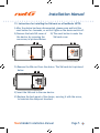
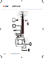
Installation
Manual
© COPYRIGHT FLEETMINDER 2013
This page has been left blank intentionally.
Publication Date August 2013
Installation Manual
Installation Manual
*These instructions are to be followed Step by Step, by ONLY a qualified installer.
ALL CONNECTIONS TO BE SOLDERED AND INSULATED!
1. Before commencing installation, please ensure that all the parts
are in the box supplied.
• If all parts are not there, please do not commence installation,
as this will mean revisiting the install more than once.
Parts should include:
1 x Fleetminder PLATINUM NXTG unit
1 GPS/GPRS combo antenna
1 Main wiring harness
1 Panic Button
fleetminder Installation Manual
Page 1
2. Find a suitable location for the Device.
• For installation and troubleshooting the 3 LED indicators should
be visible.
• Keeping in mind that the unit should be located as far away from
other electronic devices as possible. Eg. Radio, ECU…
Please note: If the unit is close to the radio, it may get GSM signal feedback
through the stereo system.
• The wiring has to be close to a power supply, otherwise the wires
may need to be extended.
• 3 metre length wire is included.
• Suggested installation locations include; under the dash, but
away from the stereo or the ECU, or in the Boot away from
speakers or any other electronic equipment.
• Please ensure that the unit is kept away from a moist and dusty
environment.
3. Fit the GPS/GPRS abtenna in a suitable location
• Keeping in mind that the GPS antenna needs a clear view of the
sky, and can’t be obstructed by metal.
• The antenna should be mounted flat side down.
(Plastic facing upwards)
• A good location is far under the dash next to heater vents, or on
the rear parcel shelf (for stealth, hide the antenna).
• Make sure that no cables get crimped during installation.
• Make sure there is enough cable length to reach the unit.
• Connect the gold connector from the GPS antenna to the gold
connector on the unit, making sure it is secured.
Page 2
fleetminder Installation Manual
Installation Manual
4. Connect the GSM antenna to the unit.
• T
he silver connector on the unit is reserved for the GSM
antenna.
5. Install a suitable place for the Panic switch.
• In most cases the switch is located on the kick panel.
• Please ensure the location will avoid accidental triggering
6. Run the Black wire to a good ground location.
• Usually the car body is an earth, so a good metal bracket is
suitable. Test the earth is solid using a Multimeter.
• Make sure it does not change state when the IGN is turned on, or
when the lights are turned on. (Some vehicles change state from
ground to +12V on some wires when the lights are turned on)
7. Run the Yellow wire to an IGN trigger, if online tracking is
required.
• If online tracking is required, Input 1 is reserved for IGN trigger.
• Run the Yellow wire to an IGN trigger which has to be 12V+ or
24V+. (Can be found on the ignition switch.)
Note: Use IGN wire that does not drop from 12V+ under crank condition.
8. Connect other Inputs and Outputs to their desired triggers
before connecting the Red wire to 12V+ or 24V+ (Please refer to
the wiring diagram for further wiring colours.)
• The outputs are all Negative Triggers (GND) and are rated to
300mA max.
• In most cases relays will have to be used for the Outputs.
• Suggested Outputs: Door Unlock, Flash Lights, Disable Starter Motor.
• Input 1 is Positive trigger (12V+ or 24V+)- Reserved for IGN
• Input 2 is Negative (GND) trigger.
fleetminder Installation Manual
Page 3
• Input 3 is Positive trigger (12V+ or 24V+)
9. Connect the RED wire to 12V+ or 24V+
10. Connect the Wiring harness to the device to turn the
Fleetminder ON!
e
• Watch the LED’s on the side of the unit to see the state of the
device. Please refer to the LED state explanation form for
reference.
Note: The YELLOW and Green LED’s will not be on until the system goes to full
working mode, normally 30 seconds after power on.
(This is in case the unit is in GPRS coverage)
Please refer to page 7 the LED Troubleshooting.
11. To test that the device is working correctly, move the vehicle
outside, ensuring that the GPS antenna has a clear view of the
sky.
For GPRS tracking, the LED indicator should show:
RED (ON), YELLOW (FLASHING), GREEN (ON)
For testing of the unit, the Primary phone number must be used using
SMS. Refer to the User manual for further instructions.
(Please refer User’s Manual [section 8.1])
12. Start tracking
• On-line Tracking
If online tracking was ordered with the device, it should already
be set up to start monitoring the location. Refer to your service
agreement which will include your username, password and the
software link.
• SMS Tracking
Refer to Command list for setting up the device using SMS.
Page 4
fleetminder Installation Manual
Installation Manual
OPEN
13. Instructions for installing the SIM card on a fleetfinder NXTG:
I) After the device has been disconnected, please press and hold the
reset button for 4 seconds, or until all lights on the device switch off.
II) Remove the back SIM cover of
III) The reset button is under the
the device, by removing the
SIM card cover.
one screw, as pictured below.
RESET
OPEN
OPEN
IV) Remove the SIM card from the device. The SIM card slot is pictured
below.
RESET
RESET
V) Insert the SIM card in the new device.
VI) Replace the back panel of the device, securing it with the screw,
to maintain the dustproof standard.
fleetminder Installation Manual
Page 5
WHITE: INPUT 3
+12/24V (TRIGGER)
YELLOW: IGNITION
+12/24V (NOT ACCESSORIES)
MUST BE LIVE WHILE CRANKING
ORANGE: OUTPUT 4 -300mA
BLUE: OUTPUT 3 -300mA
BROWN: INPUT 2
GND (TRIGGER)
GREY: OUTPUT 1 -300mA
GREEN: OUTPUT 2 -300mA
PURPLE: OUTPUT 5 -300mA
BROWN/YELLOW: OUTPUT 7 -300mA
WHITE/RED: OUTPUT 6 -300nA
WHITE
BLACK
BLACK
RED
RED
5A FUSE
OPTIONAL SOLAR BATTERY
12V or 24V
BATTERY
GARMIN INPUT
GARMIN INTERFACE CABLE
OPTIONAL TEMP SENSOR
TM600
PANIC SWITCH
GPS ANTENNA
GSM ANTENNA
RED LED: POWER INDICATOR
YELLOW LED: GSM INDICATOR
GREEN LED: GPS INDICATOR
COIL: (RFID SCANNER)
OPTIONAL SENSOR INPUT
OPTIONAL SENSOR SPLITTER
Page 6
fleetminder Installation Manual
Installation Manual
LED Troubleshooting
The Fleetminder NXTG has LED indicators on the front of the
device, that can be used for diagnosis of the device. They explain
the functionality of the device by their status explained below.
RED LED
(Power
Indicator)
YELLOW LED
(GSM/GPRS
Indicator)
GREEN LED
(GPS Indicator)
On solid state
Unit powered by main power
Flashing
- On/Off every second
Unit operating under backup battery (check vehicle
power supply)
Off
There is no power to the unit (check fuse, and
connection of the red and black wires.)
Flashing
Unit is registered on the network, and connected to
the tracking server.
On but not flashing
Unit is registered on the network, but not connected
via GPRS. – The unit is unable to connect to the server.
If the LED comes on solid, and stays on solid for a
period of about
1 ~ 2 minutes, then turns off for 30seconds, before
turning on again, this means that the device has weak
GSM signal, and it is trying to acquire GPRS.
Off
Means the device is unable to register onto the
network. Please ensure the sim card is inserted
correctly. And that the sim card is valid, and activated
(Can be checked by trialing the sim in a mobile
phone). In case there is a pin on the SIM card, please
ensure that the pin is removed (this can be done when
a sim card is inserted in a phone, by accessing the
security menu.)
On
The device is able to get a current GPS location.
Off
The device is unable to get a current GPS fix. Please
check the antenna location, and ensure that it has a
clear view of the sky.
fleetminder Installation Manual
Page 7
Further explanation of the LED functionality is described below:
RED LED
(Power
Indicator)
YELLOW LED
(GSM/GPRS
Indicator)
When the unit is powered on using main power, the LED will be permanently on.
When the main power is cut, the unit will switch to backup battery mode, the
LED will flash until the backup battery runs out of power.
Troubleshooting: Check that you have a valid 12V or 24V source connected to
the device. The Red wire should be connected to the positive terminal, and
the Black wire should be connected to the Ground terminal. If there is power
applied to these wires, please check the power supply by using a Voltmeter
across Red and Black wires of the device. If there is 12V supplied but the device
is still not powering up, please disconnect both wires, then leave the device
unplugged for 5 minutes, then reconnect. This process will reset the internal fuse
on the device.
The yellow LED will flash when the device is connected to the tracking server
with a valid GPRS connection. It will stay on continually when it is in sms mode
only, or when the GSM is present but there is no connection to the server.
Troubleshooting: If the yellow light is not on at all, please ensure the GSM
antenna is connected, and that the sim card is properly inserted, with the gold
terminals facing the circuit board. Please ensure the terminals are clean, and
the sim card clips into place appropriately. If this fails, please put the sim card
into a phone, and make sure that it is registered, and that you are able to send
a message from the phone. Please ensure the sim pin on the sim card has been
disabled (this can be done in the security settings in a mobile phone). If the
yellow light is on, but not flashing, please ensure that you have the correct APN,
username and password set for the network. The APN is usually different for each
network provider, and can be found by calling the telecommunications provider,
some telecommunications providers require a username and password to be
declared, please ensure that you have these details. The APN, username and
password can be set only from the primary defined phone number (please refer
to the Users Manual for setting primary identity). The primary phone needs to
send commands for setting the APN, username and password (these commands
can be found in the command list in the users manual) If the LED comes on
solid, and stays on solid for a period of about 1~ 2 minutes, then turns off for
30 seconds, before turning on again, this means that the device has weak GSM
signal, and it is trying to acquire GPRS. Please take the vehicle outdoors and
check the GSM reception on any phone using the same service provider.
If the problem persists, please try a different GSM antenna.
This LED will stay on when there is a valid GPS fix. When there is no GPS signal,
or the device is unable to get clear view of the sky, the LED will be off.
GREEN LED
(GPS
Indicator)
Troubleshooting: Please ensure that the GPS antenna (gold connector) is
connected to the gold antenna connection, and that it is mounted in a suitable
spot with clear view of the sky. The vehicle must be outside to be able to get
a GPS fix.
This page has been left blank intentionally.
Page 8
fleetminder Installation Manual
Installation Manual
fleetminder Installation Manual
Page 9
© Copyright Neltronics 2013
Specifications subject to change without Notice.
Page 10
fleetminder Installation Manual