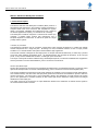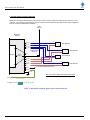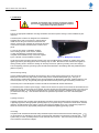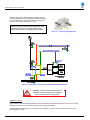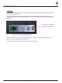
1
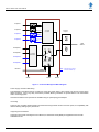
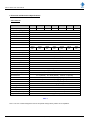
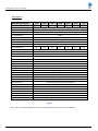
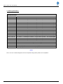
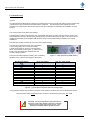
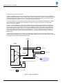
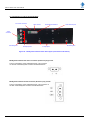
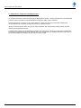
User’s Manual
MSxxxx-0x05-SP Series
VHF MiniSystem Combiner
(Single Antenna System)
Base Line 1.00
Document Number: INS41925-1
MSxxxx Series VHF User’s Manual
Company Overview
RFI has been serving the needs of the wireless communications market for over 30 years. First founded as a
manufacturer of antenna systems, RFI has grown to be a key player in the development, manufacturing and
distribution of wireless technology and energy products. Through our extensive network of resellers, systems
integrators and retail outlets, RFI is a key supplier to both industry and Government.
Our research and manufacturing facilities have talented people, sophisticated test equipment, state of the art
software with class leading manufacturing systems and techniques. Additionally, we have in place a quality
management program which is certified to ISO9001, environmental management system certification to ISO14001
and occupational health and safety standard AS4801 giving you complete confidence in everything we do.
RFI’s products are truly innovative and as a result we are active around the globe taking our Australian designed and
manufactured products to key markets in Asia Pacific, the Americas and EMEA regions via offices ‘in-region’ in
addition to exporting directly to in excess of 50 countries.
One of RFI’s key principals is to remain totally customer focused as we recognise our future depends on the success
of our customers. We know that to be chosen as your supplier we must add value to your business and to achieve
this we will work hard to deliver the best product when and where you need it and back this up with the very best
technical support available.
Asia Pacific | EMEA | Americas
2
MSxxxx Series VHF User’s Manual
Document Number INS41925-1
Copyright ã 2014 RF Industries Pty Ltd
First Printing: 04th October 2014
Version Number
Version Date
1.00
27th November 2014
_____________________________________________________________________________
Disclaimer
Product part numbering in photographs and drawings is accurate at the time of printing. Part number labels on RFI
products supersede part numbers given within this manual. Information is subject to change without notice.
Asia Pacific | EMEA | Americas
3
MSxxxx Series VHF User’s Manual
TABLE OF CONTENTS
1. GENERAL DESCRIPTION .............................................................................................................. 6
2. ELECTRICAL AND MECHANICAL SPECIFICATIONS........................................................... 8
3. ORDERING INFORMATION ........................................................................................................ 10
4. UNPACKING.................................................................................................................................... 11
5. FIRMWARE LICENSE AGREEMENT ........................................................................................ 12
6. SYSTEM INTERCONNECTION DIAGRAM .............................................................................. 13
7. INSTALLATION .............................................................................................................................. 14
8. OPERATION .................................................................................................................................... 16
9. COMMISSIONING .......................................................................................................................... 17
10. CONNECTORS, CONTROLS AND INDICATORS .................................................................. 19
11. MAINTENANCE, INSPECTION AND REPAIR ADVICE....................................................... 20
12. BACKGROUND MATERIAL AND OTHER RESOURCES .................................................... 21
13. FREQUENTLY ASKED QUESTIONS (FAQ) ........................................................................... 22
14. USER NOTES: ................................................................................................................................ 23
Asia Pacific | EMEA | Americas
4
MSxxxx Series VHF User’s Manual
Notice
The information contained in this document is subject to change without notice.
RF Industries Pty. Ltd. makes no warranty of any kind with regard to this material, including but not limited
to, the implied warranties of merchantability and fitness for a particular purpose. RF Industries Pty Ltd shall
not be liable for errors contained herein or for incidental or consequential damages in connection with the
furnishing, performance or use of the material.
All information contained in this manual has been reviewed. However RF Industries Pty Ltd accepts no
liability for any omissions, errors or construed information.
Ó 2014, RF Industries Pty Ltd. All rights reserved. Reproduction, adaptation or translation without prior
written permission is prohibited except as allowed under copyright laws.
For further information or assistance with this product contact your nearest RFI sales office or through the
following;
Region
USA
EMEA
ASIA PACIFIC
Sales email
Tech Support
Telephone Intl
Telephone local
Fax Intl
Web
[email protected]
[email protected]
+1 (330) 486 0706
330 486 0706
+ 1 (330) 486 0705
rfiamericas.com
[email protected]
[email protected]
+44 1869 255 772
01869 255 772
rfiemea.com
[email protected]
[email protected]
+61 7 3621 9400
1300 000 RFI
+61 2 9630 0844
rfi.com.au
Asia Pacific | EMEA | Americas
5
MSxxxx Series VHF User’s Manual
MSxxxx VHF Series MiniSystem Combiner
1. General Description
The MSxxxx-0x05-SP VHF MiniSystem Combiner (MSC) series is a
full featured, high performance, RF combining solution packaged in a
compact 19inch rack mount enclosure that simplifies the system
design, procurement, installation and maintenance of RF combining
for network applications requiring 1-4 channels of RF combining.
The MiniSystem Combiner comprises a multi-channel transmit (Tx)
combiner, a multiple output receiver (Rx) multicoupler, and a
bandpass duplexer to interface the Tx and Rx RF paths to a single
(Tx/Rx) antenna system.
Transmit (Tx) Combiner
The MiniSystem Combiner uses an innovative “shared load” hybrid combiner architecture to combine the multiple
transmit frequencies into a single RF path. Dual-stage, low loss, broadband isolators on each Tx input provide
excellent Tx-Tx channel isolation and optimum intermodulation (IM) suppression.
The transmit combiner is designed for full output power on all input channels simultaneously, at 100% duty cycle and
across the rated operating temperature range. Its integrated design also provides full protection, at full TX input
power, for any antenna VSWR fault condition – including an open circuit state.
The output of the hybrid combiner is filtered using a full bandpass duplexer, for transmit broadband noise suppression
and the prevention of receiver desensitisation, prior to connection to the antenna.
Receive (Rx) Multicoupler
Receive (Rx) signals from the antenna are preselected and filtered using a full bandpass duplexer, for transmit carrier
rejection and the prevention of receiver overload (blocking), prior to connection to the low-noise amplifier (LNA).
This receiver amplifier’s exceptional low noise figure optimises the sensitivity of the connected network base stations,
and excellent linearity and third order intercept (3OIP) performance enhances intermodulation rejection within the
receive sub-system. The LNA’s gain is user-configurable, allowing the adjustment of overall receiver sub-system
gain for the optimisation of network sensitivity at sites where high receive distribution cabling losses encourages
additional Rx multicoupler gain.
The output of this LNA is connected to an output distribution divider for the distribution of network receive signals to
the connected base station receivers.
Asia Pacific | EMEA | Americas
6
MSxxxx Series VHF User’s Manual
Tx Input #1
Tx Input #2
Bandpass
Duplexer
Tx Hybrid
Combiner
Tx Input #3
Tx Input #4
Tx/Rx
Antenna
Low Noise Amplifier
Rx Output #1
Power
Alarm
Rx Output #2
Rx Output
Distribution
Rx Output #3
Gain x10
Gain x1
Rx Output #4
Note:
DC Power
Ground
Alarms
Items shown in blue for
4 channel models only.
Ground
Figure 1 – 4 Channel MiniSystem Block Diagram
Power Supply and Alarm Monitoring
The MiniSystem Combiner features a wide input range DC power supply, with receiver LNA and DC power supply
failure monitoring. Form-C dry relay contacts are provided, allowing connection of reported alarms to an external site
alarm monitoring system.
100-240VAC Mains Power operation is available using an optional plug pack adapter.
Grounding
There are two grounding studs located on the left-hand and right-hand corners of the rear panel, for compatibility with
different racking cabling layout preferences.
Supporting Documentation
Supporting documents including this User’s Manual, a Quick Start Guide (QSG) and Application Note are also
available from RFI.
Asia Pacific | EMEA | Americas
7
MSxxxx Series VHF User’s Manual
2. Electrical and Mechanical Specifications
VHF 2 Channel
Model MSxxxx-0205-SP
1313
1314
1415
1516
1517
1616
1617
Frequency Range (MHz)
132-142
138-148
148-158
156-166
150-174
160-170
164-174
4MHz
min.
4MHz
min.
≤2
Tx Channel Capacity
≤ 50Watts
Tx Input Power
Tx Duty Cycle
≤ 100%
Tx-Tx Bandwidth
1.0MHz
Tx Insertion Loss
<6dB
Tx-Tx Isolation
>60dB
Tx Input Return Loss
>20dB
Tx-Antenna Isolation
Tx-Rx Separation
Tx-Rx Isolation
4MHz
min.
4MHz
min.
>50dB
4MHz
4MHz
21MHz
min.
min.
min.
65dB min. (70dB typ.)
≤2
Rx Channel Capacity
Rx-Rx Bandwidth
1.0MHz
Rx System Gain
0dB to 30dB (in 1dB steps)
Rx-Rx Isolation
>18dB
Rx LNA Noise Figure
1.2dB typ.
Rx Max. RF Input Level
-10dBm
Rx Output Return Loss
>20dB
Impedance
Alarms
Alarm Outputs
50ohms
DC Supply Voltage Low, Rx LNA Fail
Dry Relay Form-C (N.C. / N.O. / CMN)
Alarm Relay Ratings
RF Connectors
50VDC 1A max.
Tx = N (female)
Rx = BNC (female)
Antenna = N (female)
DC Connector
2pin 5mm Phoenix (mating plug supplied)
Alarm Connector
3pin 5mm Phoenix (mating plug supplied)
Enclosure
DC Power Requirements
7RU 19in Rack Mount (Black)
+11VDC to +28VDC 3.5W typ. (polarity protected)
Grounding
5mm and 6mm stainless steel studs
IP Rating
Indoor Use Only
Operating Temperature
-30° to +60° C (-122° to +140° F)
Dimensions (HxWxD)
313x483x430mm (12.33x19x17in)
Weight
18.5Kg (40.7lbs)
Table 1
Note: The 1517 model is designed for use for the special mining industry 21MHz Tx-Rx separation.
Asia Pacific | EMEA | Americas
8
MSxxxx Series VHF User’s Manual
VHF 4 Channel
Model MSxxxx-0405-SP
1313
1314
1415
1516
1517
1616
1617
Frequency Range (MHz)
132-142
138-148
148-158
156-166
150-174
160-170
164-174
21MHz
min.
4MHz
min.
4MHz
min.
≤4
Tx Channel Capacity
≤ 50Watts
Tx Input Power
Tx Duty Cycle
≤ 100%
Tx-Tx Bandwidth
1.0MHz
Tx Insertion Loss
<9dB
Tx-Tx Isolation
>60dB typ.
Tx Input Return Loss
>20dB
Tx-Antenna Isolation
>50dB
Tx-Rx Separation
4MHz
min.
4MHz
min.
4MHz
min.
Tx-Rx Isolation
4MHz
min.
65dB min. (70dB typ.)
≤4
Rx Channel Capacity
Rx-Rx Bandwidth
1.0MHz
Rx System Gain
0dB to 30dB (in 1dB steps)
Rx-Rx Isolation
>18dB
Rx LNA Noise Figure
1.2dB typ.
Rx Max. RF Input Level
-10dBm
Rx Output Return Loss
>20dB
Impedance
Alarms
Alarm Outputs
50ohms
DC Supply Voltage Low, Rx LNA Fail
Dry Relay Form-C (N.C. / N.O. / CMN)
Alarm Relay Ratings
RF Connectors
50VDC 1A max.
Tx = N (female)
Rx = BNC (female)
Antenna = N (female)
DC Connector
2pin 5mm Phoenix (mating plug supplied)
Alarm Connector
3pin 5mm Phoenix (mating plug supplied)
Enclosure
DC Power Requirements
Grounding
7RU 19in Rack Mount (Black)
+11VDC to +28VDC 3.5W typ. (polarity protected)
5mm and 6mm stainless steel studs
IP Rating
Indoor Use Only
Operating Temperature
-30° to +60° C (-122° to +140° F)
Dimensions (HxWxD)
313x483x430mm (12.33x19x17in)
Weight
22.5Kg (49.5lbs)
Table 2
Note: The 1517 model is designed for use for the special mining industry 21MHz Tx-Rx separation.
Asia Pacific | EMEA | Americas
9
MSxxxx Series VHF User’s Manual
3. Ordering Information
Ordering Information
RFI Part Number
Description
MS1313-0205-SP
132-142MHz - 2 Ch MiniSystem Combiner – Single Antenna operation – with Rx Preamplifier
MS1314-0205-SP
138-148MHz - 2 Ch MiniSystem Combiner – Single Antenna operation – with Rx Preamplifier
MS1415-0205-SP
148-158MHz - 2 Ch MiniSystem Combiner – Single Antenna operation – with Rx Preamplifier
MS1516-0205-SP
156-166MHz - 2 Ch MiniSystem Combiner – Single Antenna operation – with Rx Preamplifier
MS1517-0205-SP
150-174MHz - 2 Ch MiniSystem Combiner – Single Antenna operation – with Rx Preamplifier
MS1616-0205-SP
160-170MHz - 2 Ch MiniSystem Combiner – Single Antenna operation – with Rx Preamplifier
MS1617-0205-SP
164-174MHz - 2 Ch MiniSystem Combiner – Single Antenna operation – with Rx Preamplifier
MS1313-0405-SP
132-142MHz - 4 Ch MiniSystem Combiner – Single Antenna operation – with Rx Preamplifier
MS1314-0405-SP
138-148MHz - 4 Ch MiniSystem Combiner – Single Antenna operation – with Rx Preamplifier
MS1415-0405-SP
148-158MHz - 4 Ch MiniSystem Combiner – Single Antenna operation – with Rx Preamplifier
MS1516-0405-SP
156-166MHz - 4 Ch MiniSystem Combiner – Single Antenna operation – with Rx Preamplifier
MS1517-0405-SP
150-174MHz - 4 Ch MiniSystem Combiner – Single Antenna operation – with Rx Preamplifier
MS1616-0405-SP
160-170MHz - 4 Ch MiniSystem Combiner – Single Antenna operation – with Rx Preamplifier
MS1617-0405-SP
164-174MHz - 4 Ch MiniSystem Combiner – Single Antenna operation – with Rx Preamplifier
RX0000-3000-AC
100-240VAC / 12VDC Mains Power Plug Pack Power Supply
SP0000-6001-11
50ohm BNC (male) Termination for unused Rx Output ports
SP0000-6002-11
50ohm N (male) Termination for unused Tx Input ports
Table 3
Note: The 1517 model is designed for use for the special mining industry 21MHz Tx-Rx separation.
Asia Pacific | EMEA | Americas
10
MSxxxx Series VHF User’s Manual
4. Unpacking
CAUTION: Take all necessary precautions when lifting heavy
items. Incorrect lifting of heavy weights can cause injury.
Seek assistance, or use approved lifting devices for safety.
The MiniSystem Combiner is packed and shipped in cardboard packaging. Packed with the unit will be the Factory
Test Sheet (FTS), Quick Start Guide (QSG) and User’s Manual. Supporting documentation is also available from the
RFI website at www.rfiwireless.com.au.
The packaging used will provide suitable product protection during shipping. However, it is important to report any
visible damage to the outside of the packaging to the carrier immediately upon delivery.
It is the customers’ responsibility in the event of product damage, to lodge a damage claim with the carrier within a
short period of time after receipt of the package. The time window for lodging the claim should be ascertained from
the specific carrier as this may vary between carriers (typically 1 to 5 days).
Please dispose of all packaging material responsibly.
RECOMMENDATION: Please retain and file all Factory Test
Sheets and ongoing Periodic Maintenance Inspection results
for future reference.
The Factory Test Sheet (FTS) is a reference document that represents the MiniSystem Combiner performance at the
time of manufacture.
It is recommended to retain and file the Factory Test Sheet, and any results of ongoing Periodic Maintenance
Inspection (PMI) or other maintenance activities’ testing, to enable the ongoing performance of the MiniSystem
Combiner to be assessed and verified.
Asia Pacific | EMEA | Americas
11
MSxxxx Series VHF User’s Manual
5. Firmware License Agreement
This statement must be read in its entirety prior to the loading or use of the Firmware provided by RFI in this product.
Introduction.
By using or uploading any product related Firmware you agree without reserve with all the conditions as detailed in
this RFI Firmware License Agreement.
The term “Firmware” for the sake of this statement includes all software or firmware upgrades, either as a new
installation, revision, patches or upgrades. Any reference to software, for the purposes of this license agreement, will
therefore be included in the term Firmware.
RFI refers to the Australian registered company RF Industries Pty Ltd.
The copyright of all Firmware relating to this product remains the property in whole of RFI and is therefore protected
by the respective international copyright or trademark laws.
You agree that by using and or downloading any of the RFI product specific Firmware, that you have fully understood
and agree to comply and be bound by the all of the conditional requirements as detailed in this Firmware License
Agreement and accept the disclaimer thereof.
RFI reserves the right to update and change, from time to time, any attribute, function, feature and in the main any
content of the Firmware and any documentation attributed and referenced to the Firmware underwritten by this
Firmware License Agreement without notice to existing users.
The use of this Firmware is non-exclusive and non-sub licensable, nor does it give the user the right to re-sell, lease,
loan, distribute, or transfer the Firmware nor the rights thereof.
This Firmware License Agreement grants or implies no right, title, or interest in any intellectual property owned or
licensed by RFI.
Support and Firmware Updates.
RFI may elect to provide you with customer support and/or Firmware upgrades, enhancements, or modifications for
the RFI Firmware at its sole discretion, and may terminate such support at any time without notice to the user. RFI
may change, suspend, or discontinue any aspect of the Firmware at any time, including the availability of any
Firmware feature, database, or content.
From time to time RFI may provide notice through the RFI web site of any available updates or Firmware revision
downloads.
Fees.
RFI reserves the right to charge fees for upgrades or revisions of the applicable Firmware download.
Disclaimer.
Use of any Firmware enabling operation of the product or providing support for the product is at the user’s discretion
and risk. RFI will not be held responsible or liable for any damage or loss that results from the downloading and or
use of the Firmware or incompatibilities or other problems experienced as a result of any combination of operating
system(s), firmware, or software the user may use.
RFI will not be held responsible or liable for any inaccuracies, completeness or inadequacy regarding the Firmware
as the basis of the provision of the Firmware is on a “fit-for-purpose, best effort” approach.
RFI will not be liable to the user for claims and liabilities of any kind arising out of or in any way related to the use of
the Firmware by the user or any third party.
The failure of RFI to exercise or enforce any right or provision of this Firmware License Agreement shall not
constitute a waiver of such right or provision.
Asia Pacific | EMEA | Americas
12
MSxxxx Series VHF User’s Manual
6. System Interconnection Diagram
MiniSystem Combiners are designed to be used in a range of channel capacity configurations to suit from 1-4 RF
channels. The following system diagram shows the interconnections between the network base station equipment,
antenna system and MiniSystem Combiner;
Tx/Rx
Antenna
MiniSystem
Combiner
Tx
Tx #1
Base Station #1
Rx
Tx #2
Tx #3
Tx #4
Tx
Lightning Surge
Protector
Base Station #2
Rx
Tx
Duplexer
Tx
Tx/Rx
Antenna
Base Station #3
Rx
Rx
Rx #1
Rx #2
Tx
Rx #3
Rx
Rx #4
Alarm
Base Station #4
To Site Alarm Management System
Power
Ground
Note: Four Channel, Single Tx/Rx antenna model shown
DC In
DC or AC Power
AC In
Plug Pack
Figure 2 – MiniSystem Combiner System Interconnection Diagram
Asia Pacific | EMEA | Americas
13
MSxxxx Series VHF User’s Manual
7. Installation
CAUTION: All installation works should be conducted by qualified
personnel and in compliance with recognised standards, workplace
safety, and best engineering practices.
General
The use of appropriate installation mounting hardware that suits the specific racking or other installation style is
important.
The MiniSystem Combiner is designed to be installed into
standard 19inch rack mount frames or cabinet spaces.
Install the unit using four screws that match the 19in
racking, ensuring nylon washers are used under the head
of the screws to protect the MiniSystem Combiner front
panel.
To cater for the variety of installation locations
and mounting systems, some screws, washers
or other miscellaneous hardware items required to
complete those installations may need to be supplied
by the customer or their installation contractor.
Figure 3 – MiniSystem Combiner
An M6 stud and M5 grounding stud are located on the rear of the MiniSystem Combiner for earthing to the site’s
lightning protection grounding system with an earthing strap or cable. Both flat and lock washers are supplied on
these grounding studs to ensure the cabling can be firmly secured for optimum grounding connection integrity.
This site lightning protection grounding system should be bonded back to the building cable entry bulkhead panel
(Refer to Figure 5).
Interconnecting Cabling
Connect the Base Station transmitters and receivers to the Tx Input and Rx Output ports on the rear of the
MiniSystem Combiner using high quality coaxial cable (solid or double-shielded jacket type). The type of
interconnecting coaxial feeder cables that may be used between the MiniSystem Combiner, the Base Stations, and
Antenna system may vary, but generally their type will be determined by their length and resulting insertion loss.
Unused RF ports on the MiniSystem Combiner should be terminated with 50ohm terminations.
For the MiniSystem Combiner power supply, a cable from the chosen DC power source should be terminated into the
supplied 2-pin plug, observing the correct polarity, and then plugged into the polarised 2-pin socket on the rear of the
MiniSystem Combiner. For AC Mains powered versions, an AC-to-DC plug pack is available (as an option) with a
pre-terminated 2-Pin plug. This should be fitted into the polarised 2-pin socket on the rear of the MiniSystem
Combiner.
Lightning Protection
Lightning protection and grounding of the MiniSystem Combiner and its associated network equipment is important.
A lightning suppressor with appropriate operating frequency and power ratings, and suited for multi-carrier combiner
operation, should be fitted to the antenna system at the equipment building entry point. This lightning suppressor
should be connected to an appropriately designed and installed site lightning grounding system.
Grounding
Compliance with international electrical safety standards requires that the external Protective Earthing point
on this equipment, as indicated by this symbol, be permanently hardwired to the premise’s protective earth
system using a 1.5mm² (14AWG) minimum cross-sectional area conductor. This connection provides protection
from hazardous and transient voltages.
Asia Pacific | EMEA | Americas
14
MSxxxx Series VHF User’s Manual
Cable grounding kits, cable installation hardware, antenna
mounting hardware and antenna type(s) should be selected
to suit the network site, the antenna tower (or building, etc),
and network coverage required from the site.
NOTE: RFI can provide information and support in the
selection of cable, connectors, lightning protectors, cable
grounding kits, antennas and related installation items
required to support the use of the MiniSystem Combiner.
Figure 4 – Typical Lightning Protector
Figure 5 – Lightning Protection and Site Grounding Recommendations
WARNING: Failure to provide adequate lightning
protection and grounding may result in equipment
failure caused by electrical surge damage.
Installation Summary
The provision of adequate lightning protection, correct grounding, the appropriate torqueing of connectors and the
sealing of terminations are all important elements of any system installation.
Careful attention should be given to these areas of the installation to ensure optimum system performance and
prolonged equipment life.
Asia Pacific | EMEA | Americas
15
MSxxxx Series VHF User’s Manual
8. Operation
Supporting documents including this User Manual, a Quick Start Guide (QSG) and Application Note are supplied
with the MiniSystem Combiner.
When the MiniSystem Combiner has been installed and connected to the interconnecting coaxial cables to the
network base stations and antenna system, the power source to the MiniSystem Combiner may be connected and
switched on.
Green “Power” LED indicator.
Red “Alarm” LED indicator.
Figure 6 – Power and Alarm LED indicators
Check that the green “Power” LED indicator on the MiniSystem Combiner rear panel is illuminated, and that the
adjacent red “Alarm” LED indicator is not illuminated.
The MiniSystem Combiner is now ready for commissioning and operation.
Asia Pacific | EMEA | Americas
16
MSxxxx Series VHF User’s Manual
9. Commissioning
General
It is important that the MiniSystem Combiner is commissioned correctly to ensure that optimum system performance
is achieved from the connected network base station equipment. The following process outlines the correct
procedure for configuring the Nett Receive System Gain, and is designed to standardise the installation of these
systems.
Low Noise Amplifier (LNA) Attenuator Settings:
The MiniSystem Combiner LNA provides user-configurable attenuators for setting the Nett Receive System Gain.
These attenuators are set in the RFI factory during testing to provide a 0dB (unity) nett gain, or as close to this as
possible as determined by the available 1dB attenuator steps, and this initial setting is suitable to use in most
installations.
This attenuator setting is referred to as the RFI Factory Default setting.
Two attenuators are presented for user configuration;
a “tens” (X10) setting, and a “units (X1) setting.
A small arrow shape can be seen in the adjustment
slot on each attenuator (refer Figure 7), and this arrow
points to the associated value represented in the
currently selected position.
These slots should be adjusted carefully, with a well-fitting
adjustment tool, to prevent damaging the attenuators.
Nett Receive System
Gain
~ 0dB
1dB
2dB
3dB
4dB
5dB
6dB
7dB
8dB
9dB
10dB
11dB
Etc
Figure 7 – Gain Attenuators (40dB shown)
“X10” tens setting
LNA “X1” units setting
1
1
1
1
1
1
1
1
1
1
2
2
etc
0
1
2
3
4
5
6
7
8
9
0
1
2
Figure 8 – Typical Receive System LNA Gain configuration
The typical gain settings that should be configured on the Receive LNA attenuators can be calculated as follows;
LNA Attenuators setting equals MiniSystem Combiner “Net Receive System Gain” plus 10dB
CAUTION: The correct adjustment of these attenuators is
important, as this setting maintains protection of the base
station receivers against high level RF signals – while
obtaining the optimum available system sensitivity.
Asia Pacific | EMEA | Americas
17
MSxxxx Series VHF User’s Manual
Adjusting the Nett Receive System Gain
The gain of the MiniSystem Combiner LNA is primarily used to overcome the loss of the receive output distribution
within the MiniSystem Combiner, and the cabling losses between the MiniSystem Combiner Rx Output ports and the
connected network base station receivers - with the objective to provide a nett 0dB (unity) gain from the antenna
input of the MiniSystem Combiner, to the input of the base station receiver itself.
In most site installations, the network base stations will be mounted in close proximity to the MiniSystem Combiner,
so the insertion loss of the cables from the MiniSystem Combiner Rx Output ports through to the base station
receiver ports will be negligible.
However, in some installations, the base station equipment may be located some distance from the MiniSystem
Combiner, and in these situations the insertion loss of the cable from the MiniSystem Combiner Rx Output ports to
the base station receiver port increases the receive output distribution losses. As the length of these distribution
cables to individual base stations may vary, an “average” loss should be estimated based on the cable type and
typical length (refer to the manufacturers data sheet for values). In such circumstances, it is recommended to
increase the MiniSystem Combine LNA gain, proportionally to the “average” loss of these cables, to recover this
additional loss.
In the example shown below, the type/length of these distribution cables represents an increased receive output
distribution loss of 2dB (average). To recover this 2dB increased distribution loss, the LNA gain should be increased
by 2dB above the RFI Factory Default attenuator setting.
Tx/Rx
Antenna
MiniSystem
Combiner
Tx
Tx #1
Base Station #1
Rx
Tx #2
Tx
Rx
Tx
Duplexer
Tx/Rx
Antenna
Base Station #2
Lightning Surge
Protector
Rx
Rx #1
Rx #2
Alarm
To Site Alarm Management System
Note: If the average estimated
insertion loss of these cables is 2dB,
then increase the LNA gain by 2dB to
mai
nt
ai
n a “
net
t
0dB”
f
r
om t
he MiniSystem antenna input to the
base station receiver.
Power
Ground
DC In
DC or AC Power
AC In
Plug Pack
Figure 9 – Adjusting LNA Gain
Asia Pacific | EMEA | Americas
18
MSxxxx Series VHF User’s Manual
10. Connectors, Controls and Indicators
DC Power connector
Gain controls
Power/Alarm Indicators
Tx/Rx Antenna port
Alarm
connector
Grounding stud
Rx Output ports
Tx Input ports
Grounding stud
Figure 10 – MiniSystem Combiner Rear Panel layout (4 Channel model shown)
MiniSystem Combiner DC Power connector (Phoenix 2-pin) pin-out:
The pin configuration of the polarised Phoenix 2-pin connector
on the rear of the MiniSystem Combiner is illustrated below.
MiniSystem Combiner Alarm connector (Phoenix 3-pin) pin-out:
The pin configuration of the polarised Phoenix 3-pin connector on
the rear of the MiniSystem Combiner is illustrated below.
Asia Pacific | EMEA | Americas
19
MSxxxx Series VHF User’s Manual
11. Maintenance, Inspection and Repair Advice
No special maintenance program is required for the MiniSystem Combiner. Testing and inspection of the MiniSystem
Combiner may be included in a Periodic Maintenance Inspection (PMI) program if desired.
Checking that the RF connectors on all coaxial cables are correctly torqued (as per respective manufacturers’
recommendations) is considered good practice during any maintenance visit.
All other connectors (power, alarm, etc) must be firmly located into their corresponding mating sockets, with their
fastening screws tightened securely.
The MiniSystem Combiner is considered field repairable at a module level. Should any module within a MiniSystem
Combiner be considered faulty through diagnosis, then it may be replaced by a qualified maintenance technician - or
the complete MiniSystem Combiner may be returned to RFI for repair.
Asia Pacific | EMEA | Americas
20
MSxxxx Series VHF User’s Manual
12. Background Material and other resources
For Product Datasheets, User Manuals, Quick Start Guides (QSGs), Application Notes or additional information on
the RFI range of MiniSystem Combiners and our other products please visit:
http://www.rfiwireless.com.au
Asia Pacific | EMEA | Americas
21
MSxxxx Series VHF User’s Manual
13. Frequently Asked Questions (FAQ)
Q – Can the MiniSystem Combiner handle continuously keyed base station transmitters on all channels when
the network is heavily loaded with traffic?
A – Yes. The MiniSystem Combiner is rated for up to 50Watts of Tx Input power on each channel, and the
innovative hybrid combiner design is rated for this Tx Input power at 100% duty cycle on all channels and
across the stated operating temperature range.
Q – Does the MiniSystem Combiner need to have a full complement of network base stations fitted?
A – No. Only the initial number of channels required on the site need be connected. Unused MiniSystems
Combiner Tx Input and Rx Output ports may be left for future site capacity expansions. In this way, a 4 channel
combiner could be used, with only 2 channels initially fitted, and the remaining 2 channels of combining capacity
left for future network growth.
Q – What is the minimum channel spacing possible on a MiniSystem Combiner?
A – The MiniSystem Combiner uses an innovative hybrid combining technique that can allow adjacent Tx and or
Rx frequencies to be connected if desired.
Q – What is the maximum channel spacing possible on a MiniSystem Combiner?
A – All Tx frequencies must be within the Tx-Tx passband width of the bandpass filtering (duplexer) fitted. The
Rx frequencies must likewise all be within the Rx-Rx passband width of the bandpass filtering (duplexer) fitted.
Q – What is the minimum Tx-Rx frequency separation possible on the MiniSystem Combiner?
A – 4MHz. To provide a generic product that can be deployed into the majority of network applications, a 4MHz
minimum Tx-Rx spacing specification has been selected and used for the design of the bandpass filter
(duplexer) used in the MiniSystem Combiner.
Q – Can the MiniSystem Combiner be expanded?
A – No. The MiniSystem Combiner has been released in both 2 channel and 4 channel capacity formats that
cater for a wide range of network applications requiring from 1-4 RF channels. The 2 channel model can be
used for small network sites of 1-2 channels, and provides an entry level product for small network sites. The 4
channel model can be used for any network site of 1-4 channels, with unused Tx and Rx ports terminated and
available for future network expansion requirements.
Q – Are alarms available?
A – Yes. The MiniSystem Combiner provides a Form-C dry relay output that provides status monitoring of both
DC Input Power and Rx LNA Failure. This alarm relay output may be connected to a Base station’s external alarm
input, or existing Site Monitoring equipment, to provide MiniSystem Combiner alarm status monitoring and reporting.
.
Asia Pacific | EMEA | Americas
22
MSxxxx Series VHF User’s Manual
14. User Notes:
Asia Pacific | EMEA | Americas
23
MSxxxx Series VHF User’s Manual
11. Maintenance
No special maintenance program is required for the APM or frequency banded Couplers.
Firmware upgrades may periodically be made available and will require uploading into the APM.
Physically checking that the 7/16DIN (M) RF connectors on the feeder cables from the combiner and to the antenna are correctly
torqued (as per manufacturers recommendations) onto the corresponding Coupler termination connectors is considered good
practice. All N Male termination connectors on the RF coaxial connectors on both the APM and Coupler/s must also be tightened.
The 2-pin Phoenix DC connector socket must be firmly located and pushed into the corresponding power plug on the APM.
Neither the APM nor the Coupler/s are considered field repairable and should it be considered that either unit may be faulty
through diagnosis, they will have to be returned to RFI.
Notes:
Asia Pacific | EMEA | Americas
24