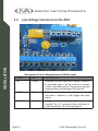
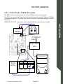
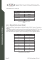
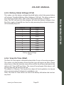
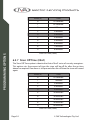
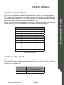
1
ZM1 User Manual
J VA T E CH N O LO G I E S
www.jva-fence.com
Contents
1Introduction. . . . . . . . . . . . . . . . . . . . . . . . . . . . . . . . . . . . . . . . . . . . . . 6
1.1
Equipment Requirements and Options. . . . . . . . . . . . . . . . . . . . . 6
1.1.1Requirements. . . . . . . . . . . . . . . . . . . . . . . . . . . . . . . . . . . . . 6
1.1.2Options. . . . . . . . . . . . . . . . . . . . . . . . . . . . . . . . . . . . . . . . . 7
2Features. . . . . . . . . . . . . . . . . . . . . . . . . . . . . . . . . . . . . . . . . . . . . . . . . . 8
2.1Limitations. . . . . . . . . . . . . . . . . . . . . . . . . . . . . . . . . . . . . . . 8
3OPERATION. . . . . . . . . . . . . . . . . . . . . . . . . . . . . . . . . . . . . . . . . . . . . . . 9
3.1
3.2
3.3
3.4
3.4.1
3.4.2
3.4.3
3.4.4
3.5
3.6
3.7
Control Options . . . . . . . . . . . . . . . . . . . . . . . . . . . . . . . . . . . . 9
Control Arbitration . . . . . . . . . . . . . . . . . . . . . . . . . . . . . . . . . . 9
Control Inputs . . . . . . . . . . . . . . . . . . . . . . . . . . . . . . . . . . . . . 9
Keypad Control . . . . . . . . . . . . . . . . . . . . . . . . . . . . . . . . . . . 10
Using the Alpha Plus LCD Keypad . . . . . . . . . . . . . . . . . . . . . . . 10
Changing the User PIN . . . . . . . . . . . . . . . . . . . . . . . . . . . . . . 11
Changing the Keypad Messages and Address . . . . . . . . . . . . . . . 11
To Exit Keypad Programming. . . . . . . . . . . . . . . . . . . . . . . . . . 12
Jumper Configuration . . . . . . . . . . . . . . . . . . . . . . . . . . . . . . . 14
LCD Display. . . . . . . . . . . . . . . . . . . . . . . . . . . . . . . . . . . . . . 15
Status LED Lights. . . . . . . . . . . . . . . . . . . . . . . . . . . . . . . . . . 16
4SPECIFICATIONS . . . . . . . . . . . . . . . . . . . . . . . . . . . . . . . . . . . . . . . . . 18
5INSTALLATION. . . . . . . . . . . . . . . . . . . . . . . . . . . . . . . . . . . . . . . . . . . 19
5.1
5.2
5.2.1
5.2.2
5.2.3
5.2.4
5.3
5.4
5.4.1
5.4.2
5.4.3
EHT Terminals on the ZM1 . . . . . . . . . . . . . . . . . . . . . . . . . . . . 19
Fence Wiring Diagrams . . . . . . . . . . . . . . . . . . . . . . . . . . . . . . 20
Configuration with NO Return Wire from Fence. . . . . . . . . . . . . . 20
Earth Loop Monitoring. . . . . . . . . . . . . . . . . . . . . . . . . . . . . . 21
Earth Stake Monitoring. . . . . . . . . . . . . . . . . . . . . . . . . . . . . . 22
No Earth Monitoring . . . . . . . . . . . . . . . . . . . . . . . . . . . . . . . 23
Low Voltage Terminals on the ZM1. . . . . . . . . . . . . . . . . . . . . . . 24
Low Voltage Wiring Diagrams. . . . . . . . . . . . . . . . . . . . . . . . . . 26
16Vac 2Amp Power Supply. . . . . . . . . . . . . . . . . . . . . . . . . . . 26
Controlling a 240Vac Energizer. . . . . . . . . . . . . . . . . . . . . . . . . 27
External Battery and Charger . . . . . . . . . . . . . . . . . . . . . . . . . . 28
6 PROGRAMMING OPTIONS . . . . . . . . . . . . . . . . . . . . . . . . . . . . . . . . 29
6.1
Programming Basics. . . . . . . . . . . . . . . . . . . . . . . . . . . . . . . . 29
6.1.1 Entering Programming Mode. . . . . . . . . . . . . . . . . . . . . . . . . . 29
6.1.2 Exiting Programming Mode. . . . . . . . . . . . . . . . . . . . . . . . . . . 29
6.1.3 Changing the Installer PIN. . . . . . . . . . . . . . . . . . . . . . . . . . . . 29
6.1.4 Changing the Installer PIN. . . . . . . . . . . . . . . . . . . . . . . . . . . . 30
6.2
Programming Options Table . . . . . . . . . . . . . . . . . . . . . . . . . . . 30
6.3
Programming Options in Detail . . . . . . . . . . . . . . . . . . . . . . . . 32
Note: The bold panel in each table indicates the default value.. . . . . . . . . . 32
6.3.1 Fence Alarm Voltage Level (01x#). . . . . . . . . . . . . . . . . . . . . . . 32
6.3.2 Current Alarm Level (02x#). . . . . . . . . . . . . . . . . . . . . . . . . . . . 33
6.3.3 Ground Voltage Alarm Level (03x#). . . . . . . . . . . . . . . . . . . . . . 33
6.3.4 Missed Pulse Count (06x#). . . . . . . . . . . . . . . . . . . . . . . . . . . . 34
6.3.5 Battery Alarm Voltage (07x#). . . . . . . . . . . . . . . . . . . . . . . . . . 35
6.3.6 Siren On Time (08x#) . . . . . . . . . . . . . . . . . . . . . . . . . . . . . . . 35
6.3.7 Siren Off Time (09x#) . . . . . . . . . . . . . . . . . . . . . . . . . . . . . . . 36
6.3.8 Siren Cycles (10x#). . . . . . . . . . . . . . . . . . . . . . . . . . . . . . . . . 37
6.3.9 Input Type (11x#). . . . . . . . . . . . . . . . . . . . . . . . . . . . . . . . . . 37
6.3.10 Gate Input Function (12x#) . . . . . . . . . . . . . . . . . . . . . . . . . . . 38
6.3.11 Gate Exit Delay (13x#). . . . . . . . . . . . . . . . . . . . . . . . . . . . . . . 38
6.3.12 Chime Mode (14x#) . . . . . . . . . . . . . . . . . . . . . . . . . . . . . . . . 38
6.3.13 Fence Mode (15x#). . . . . . . . . . . . . . . . . . . . . . . . . . . . . . . . . 39
6.3.14 Binary Options (16x#). . . . . . . . . . . . . . . . . . . . . . . . . . . . . . . 39
6.3.15 Anti-Bridging Threshold (17x#). . . . . . . . . . . . . . . . . . . . . . . . . 40
6.3.16 Auto Re-Arm Time (20x#). . . . . . . . . . . . . . . . . . . . . . . . . . . . . 41
6.3.17 Relay Functions. . . . . . . . . . . . . . . . . . . . . . . . . . . . . . . . . . . 41
6.3.18 Group Mode (26x#). . . . . . . . . . . . . . . . . . . . . . . . . . . . . . . . 43
7WARRANTY. . . . . . . . . . . . . . . . . . . . . . . . . . . . . . . . . . . . . . . . . . . . . . 45
Electric Fencing Products
1
Introduction
The ZM1 is designed to be coupled with any standard electric fence
energizer (see 2.1Limitations below) to power and monitor an electric
fence. As it can control very large energizers it is anticipated that the
ZM1 will find application on large fences for game reserves and border
security. The ZM1 uses Patent, DFD™ technology to determine if there is
a fault on very long fences. This patent has been granted South African
Patent Number 2012/03424.
The combination of the ZM1 and the energizer operate in the same
way as a single JVA Z series energizer, with the exception that the pulse
power level of the energizer cannot be modified.
Introduction
The ZM1 monitors the live feed line from the energizer to the fence and
determines if the fence is working properly by measuring the voltage
and current (therefore power) flowing to the fence. As such it does not
require a return line from the end of the fence. This can represent a
large saving on installation costs on new fences or make monitoring an
existing fence possible if no return line was originally wired. The ZM1
can, however, also monitor the return if that is desired.
The ZM1 has many programmable options which can be adjusted using
a JVA Z series keypad. By correctly setting the alarm threshold levels it
is possible to determine if a fence has been cut or shorted at any point.
The ZM1 is designed to meet or exceed the relevant parts of
IEC60335.2.76. The ZM1 is part of the JVA Z series of security energizers,
designed and manufactured in Australia.
1.1 Equipment Requirements and Options
1.1.1 Requirements
•
•
•
•
An energizer
12V rechargeable backup battery
16Vac power adaptor OR external battery charger
Security electric fence; standards, insulators, wire etc.
Some of these items may be included with the ZM1.
Page 4
© JVA Technologies Pty. Ltd.
JVA ZM1 MANUAL
1.1.2 Options
1. While the Keypad is not essential for normal operation, it is always
required for programming options during installation.
2. Up to 3 Keypads may be used with a ZM1, each Keypad must have
a unique ID setting.
For more information on these options please see
www.jva-fence.com.au
There are high voltages inside the ZM1 and JVA energizers.
The high voltage inside the energizer may take a long
time to discharge. Wait at least 10 minutes after turning off before opening the case.
Before working on the high voltage wiring of an electric fence, it is reco mended that the energizer is disarmed and a short circuit is placed from the fence live
wires to earth. This is a sensible precaution against the
energizer being armed while working on the fence.
Note: The energizer manual must also be provided to the customer as it includes mandatory safety information.
The ZM1 contains patented technology. contact JVA for more information.
www.jva-fence.com
Page 5
Introduction
• 12V Siren and strobe light
•
LCD Keypad (PTE0210). Note 1,2
• Windows PC
– Windows XP or Windows 7
– PAE223 USB to Keypad Bus or PAE212 TCP/IP adaptor
– Perimeter Patrol PC application (Pro version)
Notes:
Electric Fencing Products
2
Features
•
•
•
•
•
•
•
•
Features
•
•
•
•
•
•
•
•
•
Wall-mountable Z series energizer enclosure
Can be combined with any energizer (see 2.1 Limitations below) to
produce a full featured security electric fence energizer/monitor
Distant Fault Detection (DFD)™ allows faults to be detected on very
long fence lines (Note 1)
Anti-bridging mode, alarms on sudden change in load (Note 2)
Control and programmable via keypad with similar codes to the Z
series
Monitor fence voltage and current to trigger an alarm if current rises
or voltage falls (load increases)
Start and/or end of fence monitoring
Able to be monitored via PC (using Z control or Perimeter Patrol
software)
Run from 16Vac or 12V DC external source
Built-in battery charger and 7aH back-up battery (not included)
Can be operated from alternative larger external battery and
charger
Controls 12V DC feed to energizer
Can control a 240Vac energizer via external relay (not supplied) (12V
coil, 240Vac rated contacts)
Remote on/off or keyswitch
Gate contact input
Siren and strobe switched 12V DC outputs
3 on-board relays with many programmable functions.
2.1 Limitations
•
•
•
•
An energizer used with the ZM1 must comply with IEC60335.2.76 (or similar)
safety standard.
The ZM1 supports conventional wiring only (not Bi-Polar), although 2 units
could be used to monitor a Bi-Polar fence.
The maximum energizer power is 36 Joules (Stafix M36 or similar).
At this stage (Code Version 1.4 and earlier) a ZM1 cannot be used in a group
Page 6
© JVA Technologies Pty. Ltd.
JVA ZM1 MANUAL
either with other ZM1 units or with Z series energizers.
3
OPERATION
3.1 Control Options
3.2 Control Arbitration
If an installation contains two ways to control the ZM1/Energizer, then the most
recent control signal will determine the Armed/Disarmed state. For example, if
the ZM1 is armed via the keypad, and then disarmed at the control input (IN1),
it will disarm.
The higher level control methods such as the GSM and PC control software may
override the Control input and Keypads methods, depending on the options
used. If you need to make sure that the fence is disarmed (for maintenance) then
using the Key switch or keypad alone may not guarantee that the fence will remain disarmed.
3.3 Control Inputs
The ZM1 may have a single Key switch mounted on the right hand side of the
cabinet which may be used to arm and disarm the security electric fence to
which it is connected. This switch is useful for the simplest implementations
where no keypad or PC control program is used. It may be disabled by the in-
www.jva-fence.com
Page 7
OPERATION
The ZM1 may be armed and disarmed (controlled) using a:
• Key switch or remote switch connected to the control input (IN1)
• Remote control radio receiver connected to IN1
• Z Series Keypad
• JVA GSM module
• Windows PC running JVA Perimeter Patrol (Pro version)
• Low level interface (wired to control inputs and relay outputs) from a third
party
• security alarm panel or Physical Security Information System (PSIM)
• A high level interface
Note: More than 1 method may be used in the one installation.
Electric Fencing Products
staller, by removing the lead from socket SW2.
When switched on via the Key switch (or a switch connected to IN1) the ZM1 will
power up the energizer it is coupled to and begin monitoring the fence.
The LCD display will change to display the Feed and Ground voltages. If there is a
fence fault the ZM1 will go into alarm, the internal beeper will sound (if it has not
been inhibited) and any siren and strobe connected to the ZM1 will be turned
on.
Switching the Key switch off will disarm the ZM1, though it will continue to display the alarm.
OPERATION
3.4 Keypad Control
The ZM1 may be controlled using the PTE0210 LCD
Keypad. This keypad is also required to change
any of the programable options as described in
section 6.
The keypad will also display the fence voltages
and currents. It will also show and sound alarms
and system troubles such as AC fail.
3.4.1 Using the Alpha Plus LCD Keypad
The LCD keypad has two LED’s, Power and Arm, which act as follows:
Power – On with mains power, flashes on low battery
Arm – On when the ZM1 is armed.
All other indication is given via messages on the screen.
All other indication is given via messages on the keypad LCD screen.
If the Keypad shows “Alarm” or “Trouble” pressing [#] will reveal more information
about the problem.
3.4.2 Arming and Disarming with the Keypad
Enter your User PIN (Personal Identification Number: four digits long) and push
the # key. Make sure the red ARM light comes on and the keypad beeps twice to
Page 8
© JVA Technologies Pty. Ltd.
JVA ZM1 MANUAL
confirm that the system is armed.
The fence will power up and if all is well (no faults) the system will be ready to
deter and detect.
To disarm the system enter your User PIN and press #.
Note: If there is an alarm sounding you will need to enter your PIN twice, once to
silence the alarm and once more to disarm.
Enter the old USER PIN followed by *0# (star, zero, hash). Enter new 4-digit USER
PIN and # (hash).
3.4.4 Changing the Keypad Messages and Address
You can change the messages and each of the 8 zone labels.
The Dealer Message displays when the system is on standby.
Zone labels display after the [#] key is pressed during alarm memory or faults.
The programmable Service Message is displayed during AC failure, fuse failure,
communication failure, or low battery.
Keys used for changing messages
[1]
[2] Character up
[3] not used
Emergency
used
[4] Cursor left
[5] Next Message
[6] Cursor right
Fire not used
[7]
[8] Character down
[9]
Panic not used
[*]
[0] Last Message
[#] Enter/Exit
Bypass not used
•
not
To activate the keypad programming mode, enter the [Installer ’s PIN]
[*] [0][1][#]. Information may be entered into the keypad in the form of
letters (upper and lower case), numbers (0 – 9), and 22 special symbols. All
www.jva-fence.com
Page 9
OPERATION
3.4.3 Changing the User PIN
Electric Fencing Products
characters are displayed in the order: upper and lower case letters, numbers,
and special symbols. The [Space] character precedes the letter A.
•
To enter a Label, use the [2] key to scroll through the characters until you
reach the desired character. If you scroll past the desired character, the [8]
key may be used to scroll backwards. Note: The space character is before the
A character (When A is displayed, press [8] to create a space).
•
When the desired character is displayed, press the [6] key to move the cursor
to the next character position. The [4] key moves the cursor to the left.
•
When all characters have been entered, press the [#] key to enter the
message and move to the next message position.
•
Use the [0] key to move backward through the messages.
•
To change the keypad address, scroll through the messages until the keypad
displays: Keypad Address then change the value by pressing [2] (up) or [8]
(down). Validate by pressing #
OPERATION
NOTE: If you move to the next message using [5] instead of the [#] key, you will
lose any changes you made!
Notes on keypad addresses:
Up to 3 keypads can be used in a system. When using 2 or 3 keypads in a system,
one of the keypads MUST be set to address 2 and the second one should be
set to a value between 1 – 7. Do not set this to address 8 as this address uses a
different protocol. If a third keypad is used, its ID must also be set to a unique
value between 1 and 7.
The message order is:
•
•
•
•
•
SERVICE MESSAGE (Displayed under SYSTEM TROUBLE)
DEALER MESSAGE (Displayed under the standby message: READY TO ARM)
SOFT ZONE IDENTIFIERS (A, B, and C) (not used)
HARDWIRED LOOP IDENTIFIERS (Zone 1 = Gate, Zone 3 = Fence)
KEYPAD ADDRESS (should be left at 1 for energizers with firmware older
than7V51)
3.4.5 To Exit Keypad Programming
When you have finished programming, press [*] [#]
Page 10
© JVA Technologies Pty. Ltd.
JVA ZM1 MANUAL
Note: The keypad will also exit the programming mode if you do not press any
key within a five minute period.
Summary of LCD Keypad Functions
Key Sequence
Arm/Disarm
[User PIN][#]
Silence an alarm (Single zone
system only)
[User PIN][#] Start Programming the Z series
energiser
[Installer PIN][*] [0] [#]
Start Programming the Keypad
[Installer PIN][*] [0] [1] [#]
Exit Programming (any mode)
[*] [#]
Change a User PIN, 4 Digits
[User PIN][*]0[#][New PIN]#
Change the Installer PIN, 5 Digits
[0] [0] [New Installer PIN][#]
Arm All
groups)
[User PIN][*][1][0][#]
Zones (Multi-zone
Arm Zone 1 (Master)
[User PIN][*][1][1][#]
Arm Zone x, where x is any zone
number up to 15
[User PIN][*][1][x][#]
Disarm All Zones
[User PIN][*][2][0][#]
Disarm Zone 1 or Master
[User PIN][*][2][1][#]
Disarm Zone x, where x is any
zone number up to 15
[User PIN][*][2][x][#]
Switch to low power mode (all
zones)
[User PIN][*][4][1][#]
Switch to high power mode (all
zones)
[User PIN][*][4][2][#]
Arm Gate circuits only
[User PIN][*][4][#]
To change the Keypad Messages
to English
[*][3][1][#]
To change the Keypad Messages
to Spanish
[*][3][2][#] (not well supported
yet)
www.jva-fence.com
Page 11
OPERATION
Function
OPERATION
Electric Fencing Products
Function
Key Sequence
Keypad Audible Feedback On/
Off
[*] [5] [1] [#]
Keypad Chimes Toggle On/Off
[*] [5] [3] [#]
Keypad Error Tones On/Off
[*] [5] [4] [#]
Keypad Alarm Tones Toggle On/
Off
[*] [5] [5] [#]
Backlight Toggle On/Off
[*] [8] [#]
Display Keypad Model
[*] [9] [#]
Analyse group
[*][6][8][#]
Reset and Display firmware version number
[User PIN][*][6][8][#]
Reset and return to factory defaults
[Installer PIN][*] [6] [8] [#]
Siren test
[*] [6] [3] [#]
Battery test
[*] [6] [4] [#]
Show Balance
[*] [6] [5] [#]
Show Saved Zone Splits (while
disarmed)
[*] [6] [6] [#]
Clear Alarm memory
[*] [1] [#]
The ZM1 is equipped with four jumpers. Two of them (J3 and J4) are special
purpose jumpers (links). The purpose of each is listed in the table below.
3.5 Jumper Configuration
The ZM1 is equipped with four jumpers. Two of them (J3 and J4) are special purpose jumpers (links). The purpose of each is listed in the table below.
Page 12
© JVA Technologies Pty. Ltd.
JVA ZM1 MANUAL
FUNCTION
PURPOSE
J3
DC only jumper
Install J3 to inhibit Mains fail errors if the intention is to operate the energiser on DC only (as
in solar power systems).
J4
Factory
jumper
If the monitor unit needs to be
defaulted to factory settings,
remove all power – mains and
battery – and remove the J4
jumper.
Reapply the battery power
first, and then the mains power.
Reapply the J4 jumper and the
unit will be reset to default settings. If Status LED flashes four
times after defaulting the unit,
return it to the nearest JVA service centre.
default
The 3rd jumper, J5, when fitted, will suppress the beeper on the ZM1.
The fourth jumper (J6) allows the supply voltage for the energizer to be set. If
the top two pins are selected (12V Regulated) then the energizer supply voltage
will be the same as the PAE202 battery voltage (between 12 and 14.5 volts). If
the bottom two pins are selected (24V Unregulated) the voltage supplied to the
energizer will depend on the type and size of AC power adapter used, but maybe
as high as 24 volts.
3.6 LCD Display
The LCD display on the ZM1 will switch between two different display modes.
The mode shown can be identified by the feed and return LED’s on the status
panel.
The picture on the left below shows the feed mode, which shows the voltage at
the start of the fence, and the current flowing into the fence. The picture on the
right shows the voltage at the end of the fence, and the ground voltage.
Note that the return voltage can be inhibited with programming option 15 if
www.jva-fence.com
Page 13
OPERATION
JUMPER
Electric Fencing Products
only the start of the fence is to be monitored.
OPERATION
3.7 Status LED Lights
The status LED’s on the front of the ZM1 allow the user to quickly ascertain the
current status of the unit and if any action needs to be taken. Below is a brief
description of each LED (from left to right, top to bottom) and the information
it conveys.
Power – On whenever the unit has power
Feed – Tells the user that the LCD is displaying the Feed Voltage (left) and Fence
Current (right)
Armed –On when the unit is armed (pulsing)
Return –Tells the user that the LCD is displaying the Return Voltage (left) and
Ground Voltage (right)
Fence – On when there is a fence alarm (either channel)
Gate – On when there is a gate alarm
Ground – On when there is a ground alarm (specific meaning will vary depend
ing on ground configuration) (Please refer to the installation chapter
for more information.)
Status – Flashes an error code for monitor (service) errors. These error codes are
identical to the Z energizer range. The table below shows the Status
LED Error Codes.
Page 14
© JVA Technologies Pty. Ltd.
JVA ZM1 MANUAL
Interpretation
Corrective Action
2
16Vac mains fail
Restore mains power
3
Low battery, bad battery
Charge or replace battery
4
PCB service fault
Return to repair/service
centre.
Note: A Z slave will show
this error if disconnected from the Master.
www.jva-fence.com
Page 15
OPERATION
Error LED
Number of
Flashes
Electric Fencing Products
4
SPECIFICATIONS
SPECIFICATIONS
The specifications table below outlines the power consumption of the ZM1 and
the acceptable voltage and current ranges for different inputs and outputs.
Internal battery charger float voltage
14.3Vdc
Internal battery charger charging current
580mA
Absolute maximum power consumption
of ZM1 (Note 1)
85mA at 12.5Vdc
Maximum AC input voltage when internal
battery charger is supplying 580mA
19Vac
Maximum DC energizer current from ENERGIZER powered output if using 16Vac
supply and internal battery
2.3 Amps
Amps maximum DC energizer current
from ENERGIZER powered output if using
external power supply and battery
10 Amps
Maximum voltage on In1, SW2 and Gate
inputs (Note 2)
5Vdc
Maximum power provided to Siren and
Strobe outputs (Note 3)
35Watts
Maximum fence voltage
9.9kV
Maximum fence current
80 Amps
Recommended operating temperature
–15°C to +50°C
Note 1: This is the power consumption when none of the powered outputs are
active and the keypad is not connected. The rated power consumption may be
lower depending on relay configuration and alarm states.
Note 2: The control inputs, In1, SW2 and Gate supply their own power (5 volts,
limited to 220nA). If a powered control system is connected to these inputs, the
control voltages must not exceed 5 volts.
Note 3: The rated power is the combined output power of both the Siren and
Strobe outputs. The voltage which can be expected on this output is the battery
Page 16
© JVA Technologies Pty. Ltd.
JVA ZM1 MANUAL
voltage. The combined maximum output current of both these outputs is 2.5
Amps. Note that the maximum output power will drop as battery voltage drops.
5
INSTALLATION
INSTALLATION
5.1 EHT Terminals on the ZM1
Description of high voltage terminals (left to right)
EHT In
Connect the high voltage output of the energizer to this
terminal to allow fence current to be measured.
Feed
Connect the start of the fence to this terminal. Voltage at
Feed will be the same voltage as EHT In.
Return
Connect the start of the fence to this terminal. The Return
voltage will normally be lower than the Feed voltage.
Not Used
This terminal is unused at this time.
Ground
Ref
Reference ground connection. Please refer to diagrams
Earth Loop Monitoring, Earth Stake Monitoring and No
Earth Monitoring for information on how to configure this
input.
Ground
Main fence earth. Please refer to diagrams Earth Loop Monitoring, Earth Stake Monitoring and No Earth Monitoring
for information on how to configure this input.
www.jva-fence.com
Page 17
Electric Fencing Products
5.2 Fence Wiring Diagrams
There are a number of ways the fence wires can be connected to a ZM1. The following diagrams will outline different ways in which the ground circuit can be
configured and what the benefits of each are.
5.2.1 Configuration with NO Return Wire from Fence
INSTALLATION
NOTE: Please refer to programming option Fence Mode (point 6.3.13).
Page 18
© JVA Technologies Pty. Ltd.
JVA ZM1 MANUAL
5.2.2 Earth Loop Monitoring
The set up pictured below will detect if the ground wire has been cut. Connect
the Ground Reference input to the energizer Earth, and the Ground input to the
other end of the earth fence loop.
High Powered Energiser
Ground
Ground Reference
Feed
Return
High Voltage
Energiser Earth
www.jva-fence.com
Page 19
INSTALLATION
Earth
High Voltage
Conventional Fence
Electric Fencing Products
5.2.3 Earth Stake Monitoring
This setup will check how well the energizer is earthed. Connect the Ground,
Reference input of the ZM1 to the mains earth, or the cabinet earth. This Ground
Reference must be more than 10m away from the Energizer Earth.
High Powered Energiser
Ground
Ground Reference
Feed
Return
High Voltage
INSTALLATION
Earth
High Voltage
Conventional Fence
Energiser Earth
Page 20
© JVA Technologies Pty. Ltd.
JVA ZM1 MANUAL
5.2.4 No Earth Monitoring
This setup will monitor only the fence feed and return voltages and fence current. Connect the Ground Reference and Ground inputs to each other with a
short piece of wire.
High Powered Energiser
INSTALLATION
Earth
Ground
Ground Reference
Feed
Return
High Voltage
High Voltage
Conventional Fence
Energiser Earth
www.jva-fence.com
Page 21
Electric Fencing Products
INSTALLATION
5.3 Low Voltage Terminals on the ZM1
Description of low voltage terminals (left to right)
LABEL
TYPE
DESCRIPTION
IN1
2 Way
Energizer control input (dry contact). Defaults
to normally open. Can be used for a remote
switch or a radio receiver. The receiver may be
powered from the keypad+12V terminal.
GATE
2 Way
ZM1 Gate Input, when the unit is armed and
the gate is opened, it will trigger the gate
alarm.
KEYPAD
3 Way
Supplies power and data line for an external
keypad. The +12 source on these terminals is
protected with a 1A self resetting fuse.
Page 22
© JVA Technologies Pty. Ltd.
JVA ZM1 MANUAL
TYPE
DESCRIPTION
SIREN
2 Way
Switched 12 volt output. Low side switched.
35W max (including strobe). A buffer relay
should be used when connecting these outputs to an alarm panel.
STROBE
2 Way
Switched 12 volt output. Low side switched.
35W max (including siren). A buffer relay
should be used when connecting these outputs to an alarm panel.
Energizer
Power
3 Way
Powered output which is enabled when the
ZM1 is armed. Power is drawn from the ZM1
battery and 16Vac power supply, or from the
EXT 12V input.
EXT 12V
2 Way
Input used for DC energizers which exceed
the supply rating of the 16Vac transformer
(greater than 12 Joules output).
16V AC IN
3 Way
16Vac power input. Fused via F3 3A self resetting fuse.
Relay 3
3 Way
May be set to any of 16 alarm conditions.
Relay 4
3 Way
May be set to any of 16 alarm conditions.
Relay 5
3 Way
May be set to any of 16 alarm conditions.
Batt
Leads
12V dc or battery connection via F1 (3 Amp
self resetting fuse). Connect Red lead to battery positive (+) terminal. (not pictured on
page 24)
SW2
2 Way
Energizer control input. Normally connected
to a keyswitch (not pictured on page 24).
www.jva-fence.com
Page 23
INSTALLATION
LABEL
Electric Fencing Products
5.4 Low Voltage Wiring Diagrams
5.4.1 16Vac 2Amp Power Supply
The ZM1 can be used to power an external high powered energizer. A 16Vac
2Amp power supply is able to power a B8 or B12 (or equivalent) energizer as well
as the ZM1 and keep the backup battery charged.
WARNING: The DC voltage supplied to the energizer will be the rectified voltage
of the 16Vac which may be as high as 30Vdc.
Larger energizers will need to utilise the external 12 volt power supply input.
- +
+ BATT -
INSTALLATION
12v SLA
Battery
16v AC
2A PSU
+12V Gnd +12V Gnd
ENERGISER EXT 12V
Output
Input
Page 24
16Vac
E
© JVA Technologies Pty. Ltd.
JVA ZM1 MANUAL
5.4.2 Controlling a 240Vac Energizer
The ZM1 can be used to power an external high-powered energizer.
The ZM1 can control an external relay box designed to switch 110Vac or 240Vac
powered energizers. The relay box needs to accept switching voltages of up to
13.8 volts.
WARNING: DO NOT use relay 3, 4 or 5 on the ZM1 to switch mains voltage.
+ BATT -
12v SLA
Battery
110/240V AC
Input
Mains Relay
Box
16v AC
2A PSU
+12V Gnd +12V Gnd
ENERGISER EXT 12V
Output
Input
www.jva-fence.com
16Vac
E
Page 25
INSTALLATION
- +
Electric Fencing Products
5.4.3 External Battery and Charger
Larger 12Vdc energizers will need to utilise an external 12 volt power supply.
INSTALLATION
To power the ZM1 from the external battery and charger, ensure Jumper J6 is
placed on the 12V regulated pins. Do not connect a 16Vac supply to the ZM1.
+12V Gnd +12V Gnd
ENERGISER EXT 12V
Output
Input
16Vac
E
External
13.8V dc
Charger
-
12v SLA
Battery
Page 26
+
© JVA Technologies Pty. Ltd.
JVA ZM1 MANUAL
6
PROGRAMMING OPTIONS
6.1 Programming Basics
Some of the programming options on the ZM1 are different to those on the Z
series of security energizers, but the basic functions remain the same.
6.1.1 Entering Programming Mode
To enter programming mode, enter the 6 digit installer PIN followed by *0# keys.
The keypad will beep twice to indicate that the command was accepted. If the
PIN was incorrect the keypad will beep 3 times. The LCD will now show the first
programming option and its current setting.
Pressing the # key will cycle through all the options on the LCD.
Note: Not all numbers are used. The default installer PIN is 012345.
6.1.2 Exiting Programming Mode
To exit programming mode once programming has been completed, press*#
. If left unattended, the unit will time out and auto exit after approximately 5
minutes.
6.1.3 Changing the Installer PIN
The installer PIN may only be changed while in programming mode.
To enter a new installer pin, press 00 followed by the new 6 digit installer
PIN, then the # key.
If you cannot remember your installer or user PIN, return the units memory to
default. To do this, remove power (AC off and disconnect the battery), open the
energizer, remove jumper J4 and reconnect the battery for about 10 seconds.
Do not forget to re-fit J4. This will return all options to the factory set defaults.
www.jva-fence.com
Page 27
PROGRAMMING OPTIONS
Like the Z series of security energizers, the ZM1 has a non-volatile memory in
which programming options (or setup parameters) can be stored. These are
factory pre-set, but can be field programmed using a keypad.
Electric Fencing Products
6.1.4 Changing the Installer PIN
Most of the options have possible values in the range of 0 to 9.
To change any options, first check the option number (see table on page 24) and
then the Programming Options in Detail on page 25. Then press the option
number followed by the required value. For example, to change the Missed
Pulse Count (Option 06) to maximum (9 is the Maximum) press 069#, the keypad
will beep twice to indicate that the command was successful. The ZM1 LCD will
immediately show the updated value.
PROGRAMMING OPTIONS
6.2 Programming Options Table
OPTION
FUNCTION
DESCRIPTION
01
Fence alarm
voltage level
Sets the voltage below which the
fence alarm will occur. If the feed
OR return voltage falls below this
level for more than the Missed
Pulse Count a fence alarm (Zone 1)
will occur. If the return voltage is
not being used set option 15 to 1.
02
Current alarm
level
Sets the threshold to alarm on
current from the feed terminal to
the fence. If the feed current rises
above this level for more than the
Missed Pulse Count a fence alarm
(Zone 1) will occur.
03
Ground
Voltage alarm
level
Sets the voltage above which
the fence alarm will occur. If the
ground voltage rises above this
level for more than the Missed
Pulse Count a ground alarm (Zone
2) will occur.
06
Missed Pulse
Count
Sets the number of pulses which
may be missed before the alarm is
activated.
Page 28
© JVA Technologies Pty. Ltd.
JVA ZM1 MANUAL
FUNCTION
DESCRIPTION
07
Battery Alarm
Voltage
Sets the battery voltage threshold
below which the general alarm
will activate.
08
Siren On Time
Sets the time that the siren (and
keypad beeper) will stay on after
an alarm.
09
Siren Off Time
The amount of time the siren will
remain off after the On Time has
expired.
10
Siren Cycles
The number of times the siren will
sound for the time set in On Time
above. After this many cycles the
siren will automatically mute.
11
Input type
Allows the ZM1 inputs to be
changed from normally open to
normally closed.
12
Gate Input
Function
Gate switch only for now.
13
Gate Exit
Delay
Duration of time from gate switch
opening to alarm.
14
Chime Mode
Allows the keypad and internal
beeper function to be altered.
15
Fence Mode
Set to 1 if using start of fence only,
removes return voltage from display and alarm.
16
Binary
tions
Miscellaneous options
17
Anti-Bridging
www.jva-fence.com
Op-
Sets the % threshold for alarm on
a sudden rise or fall of fence current.
Page 29
PROGRAMMING OPTIONS
OPTION
PROGRAMMING OPTIONS
Electric Fencing Products
OPTION
FUNCTION
DESCRIPTION
20
Auto Re-Arm
Time
Sets the time which must elapse
after an alarm has timed out
(completed the siren cycles) before the unit will automatically
re-arm ready for the next alarm
event.
21
Relay 1
Used to assign an alarm function
to relay 1 (siren output)
22
Relay 2
Used to assign an alarm function
to relay 2 (strobe output)
23
Relay 3
Used to assign an alarm function
to relay 3
24
Relay 4
Used to assign an alarm function
to relay 4
25
Relay 5
Used to assign an alarm function
to relay 5
26
Group ID
If used as part of a SCADA system,
this sets the device ID
6.3 Programming Options in Detail
Note: The bold panel in each table indicates the default value.
6.3.1 Fence Alarm Voltage Level (01x#)
This option sets the voltage below which the fence alarm will occur. If the feed
OR return voltage falls below this level for more than the Missed Pulse Count a
fence alarm (Zone 1) will occur. If the return voltage is not being used, set option
15 to 1.
Unlike the other Z series energizer the value is set directly, not via a table. For
example to set a threshold of 5.0kV enter: 0 1 5 0 # (Do not enter the decimal!)
The default level is 4.0kv (40).
Page 30
© JVA Technologies Pty. Ltd.
JVA ZM1 MANUAL
Value (x)
Alarm Level
Minimum
0.0 kV
40
4.0kV
Maximum
99
9.9 kV
Fence Alarm Voltage Level
(01x#)
6.3.2 Current Alarm Level (02x#)
This option sets the threshold to alarm on current from the feed terminal to the
fence. If the feed current rises above this level for more than the Missed Pulse
Count a fence alarm (Zone 1) will occur.
Unlike the other Z series energizer, the value is set directly, not via a table. For
example to set a threshold of 5A enter: 0 2 0 5 #
The default level is 10A.
Value (x)
Alarm Level
Minimum
0
0 Amps
10
10 Amps
Maximum
75
75 Amps
Current Alarm Level (02x#)
6.3.3 Ground Voltage Alarm Level (03x#)
This option sets the voltage above which the fence alarm will occur. If the ground
voltage rises above this level for more than the Missed Pulse Count a ground
alarm (Zone 2) will occur.
Unlike the other Z series energizer, the value is set directly, not via a table. For
example, to set a threshold of 2.0kV enter: 0 3 2 0 #
Do not enter the decimal!
www.jva-fence.com
Page 31
PROGRAMMING OPTIONS
0
Electric Fencing Products
The default level is 1.0kv (10)
Value (x)
Alarm Level
Minimum
0
0.0 kV
10
1.0 kV
Maximum
50
5.0 kV
Ground Voltage Alarm Level
(03x#)
PROGRAMMING OPTIONS
6.3.4 Missed Pulse Count (06x#)
The Missed Pulse Count option is identical to that of the Z series of security energizers.
This option enables the pulse count to be varied from the default (3). This is the
number of bad or missing pulses that are counted before the alarm occurs.
Note: The lower this option is set, the more likely you are to get false alarms.
Value (x)
Missed Pulses
0
1
1
1
2
2
3
3
4
4
5
5
6
6
7
7
8
8
9
9
Missed Pulse Count (06x#)
Page 32
© JVA Technologies Pty. Ltd.
JVA ZM1 MANUAL
6.3.5 Battery Alarm Voltage (07x#)
Value (x)
Alarm
0
9.0V
1
19.5V
2
10.0V
3
10.5V
4
11.0V
5
11.5V
6
12.0V
7
12.5V
8
13.0V
9
13.5V
Battery Alarm Voltage
(07x#)
6.3.6 Siren On Time (08x#)
The Siren On Time option is identical to that of the Z series of security energizers.
This option sets the duration of time that the siren will remain on after a fence
alarm occurs. After this time the siren will turn off for the off time indicated in the
table in 6.3.7 Siren Off Time Values. The siren will sound again if the alarm is still
present after this off time has passed.
The default is 3 Minutes. This may be the subject of local regulations to stop an
alarm causing undue disturbance to neighbours, etc.
Note: The Siren On Time will be cut short if the battery falls below the low battery level.
www.jva-fence.com
Page 33
PROGRAMMING OPTIONS
This option sets the battery voltage threshold below which the general alarm
will activate. The default Battery Alarm Voltage is 10.0 Volts. This alarm can be set
to activate one of the relays, and is part of the General alarm, see below.
Note: The ZM1 will not turn the energizer off when the battery voltage is low.
But if the supply voltage falls too low the relay powering the external energizer
will eventually drop out.
Electric Fencing Products
PROGRAMMING OPTIONS
Value (x)
Time
0
10 Seconds
1
30 Seconds
2
1 Minute
3
2 Minutes
4
3 Minutes
5
4 Minutes
6
5 Minutes
7
6 Minutes
8
7 Minutes
9
8 Minutes
Siren On Time (08x#)
6.3.7 Siren Off Time (09x#)
The Siren Off Time option is identical to that of the Z series of security energizers.
This option sets the amount of time the siren will be off for after the on time
above has expired. If an alarm is still present after this off time the siren will sound
again.
Value (x)
Time
0
10 Seconds
1
1 Minute
2
2 Minutes
3
5 Minutes
4
10 Minutes
5
20 Minutes
6
30 Minutes
7
40 Minutes
8
50 Minutes
9
60 Minutes
Siren On Time (09x#)
Page 34
© JVA Technologies Pty. Ltd.
JVA ZM1 MANUAL
6.3.8 Siren Cycles (10x#)
Value (x)
Cycles
0
1
1
1
2
2
3
3
4
4
5
5
6
6
7
7
8
8
9
9
Siren Cycles (10x#)
6.3.9 Input Type (11x#)
The Input Type option is identical to that of the Z series of security energizers.
The control inputs can be inverted unless an input is used for a Gate switch, in
which case it is always NC.
Value (x)
Input type
0
NO Normally open
1
NC Normally closed
Input Type (11x#)
www.jva-fence.com
Page 35
PROGRAMMING OPTIONS
The Siren Cycles option is identical to that of the Z series of security energizers.
This option sets the maximum number of times the siren will sound for the On
Time if the alarm continues. This may be limited by local regulations to stop an
alarm causing undue disturbance to neighbours, etc.
Note: This is the maximum number of cycles for 1 continuous alarm. Intermittent
alarm events could cause more than this number of siren soundings.
Electric Fencing Products
6.3.10Gate Input Function (12x#)
This input can not be configured to anything other than a Gate input at this time.
6.3.11Gate Exit Delay (13x#)
PROGRAMMING OPTIONS
The Gate Exit Delay option is identical to that of the Z series of security energizers. This option sets the time between the gate switch opening and the siren
sounding.
Value (x)
Function
0
0 Seconds
(immediate)
1
30 Seconds
2
1 Minute
3
2 Minutes
4
3 Minutes
5
4 Minutes
6
5 Minutes
7
6 Minutes
8
7 Minutes
9
8 Minutes
Gate Exit Delay (13x#)
6.3.12Chime Mode (14x#)
The Chime Mode option is identical to that of the Z series of security energizers.
This option allows the energizer internal and keypad beeper to be used as a door
chime for the gate switch. When set to None, the keypad beeper is used to indicate correct keypad operation only. In Door Chime mode, the beepers sound
when the gate switch opens, even if the energizer is disarmed.
Note: Gate must be selected in option 12.
If set to Siren, the beepers mimic the siren function.
Gate Beeps plus Siren will give 2 beeps when the gate starts opening and 4
beeps when it closes, plus continuous beeps for an alarm. Beeps are on the key-
Page 36
© JVA Technologies Pty. Ltd.
JVA ZM1 MANUAL
pad only, not on the internal beeper.
Function
0
None
1
Door Chime
2
Siren
3
Fence Alarm
4
Gate beeps plus Siren
Chime Mode (14x#)
6.3.13Fence Mode (15x#)
This option configures if the return voltage should be monitored. If set to 1, this
option will stop the return voltage from being displayed on the LCD, and inhibit
any alarms which may normally be triggered owing to no voltage being present
on the return input.
Value (x)
Function
0
Monitor Return
1
Feed only
Fence Mode (15x#)
6.3.14Binary Options (16x#)
Each option in this table can be turned on by adding the value.
For option +1 set 16 to 01, for +1 and +2 set 16 to 03.
+1: Enable DFD™ (Distant Fault Detection). Firmware V1.40 and later, PCB V1.10
and later.
DFD™ enables the ZM1 to detect a fault at the end of very long fences. Instead of
only measuring the peak current the ZM1 with DFD™ calculates the “real” current
and rejects the “reactive” current.
The current displayed will usually be less than read by a standard hand-held
meter with this feature on. There is no theoretical limit to the length of fence
that the ZM1can monitor with this feature on. Without DFD™ the limit is approxi-
www.jva-fence.com
Page 37
PROGRAMMING OPTIONS
Value (x)
Electric Fencing Products
mately 8km.
* DFD™ is Trade Mark and Patented.
Value (x)
Function
0
None
+1
Engage DFD*
Binary Options (16x#)
PROGRAMMING OPTIONS
6.3.15Anti-Bridging Threshold (17x#)
Anti-Bridging has been designed to detect a section of fence being bypassed,
and removed, by an intruder bridging the adjacent fence sections together. This
also detects when the feed is connected to the return with a short cable, and
then the entire fence is cut.
Setting this option to a value greater than 0 (default is 0 = off) will enable AntiBridging.
While Armed, a Fence Alarm will trigger if the Fence Current rises OR falls quickly
by more than the threshold. A slow change to the Current will not trigger a Fence
Alarm until the Current is more than the Current Alarm Level (02x#).
The Anti-Bridging Threshold is a percentage value of the Fence Current. For example, setting option 17 to 50 (1750#) will set a 50% Anti-Bridging Threshold. At
this level a Fence Current normally reading 10Amps will trigger a Fence Alarm if
the Current quickly rises to over 15A or falls to less than 5A.
Measuring fence current to determine if a fence is bridged will work irrespective
of the energizer type powering the fence.
Value (x)
Threshold
Minimum
0
Disabled
Maximum
90
90%
Anti-Bridging Threshold
(17x#)
Page 38
© JVA Technologies Pty. Ltd.
JVA ZM1 MANUAL
6.3.16Auto Re-Arm Time (20x#)
Value (x)
Time
0
0 Seconds
(Immediate)
1
30 Seconds
2
1 Minute
3
2 Minutes
4
3 Minutes
5
4 Minutes
6
5 Minutes
7
6 Minutes
8
7 Minutes
9
Disabled – Do not
auto rearm
Auto Re-Arm Time (20x#)
6.3.17Relay Functions
All relays can be set to any of the available functions (user assignable).
Relay 1 is (21x#)
Relay 2 is (22x#), etc
www.jva-fence.com
Page 39
PROGRAMMING OPTIONS
The Auto Re-Arm Time option is identical to that of the Z series of security energizers.
This option sets the time which must elapse before another alarm will sound
after the first alarm has timed out (gone completely through its cycles).
If an event occurs (such as a low fence voltage) which triggers the siren, any
other events which would otherwise trigger the siren (such as a gate alarm) will
be ignored while the siren is sounding and until after the Auto Re-Arm time has
passed.
A setting of 9 will disable auto Re-Arm.
If this time is set to less than the Siren Off Time, the unit may re-arm in the siren
off time and the number of siren cycles will be reduced.
Electric Fencing Products
PROGRAMMING OPTIONS
Defaults for the ZM1:
• Relay 1 – Siren
• Relay 2 – Strobe
• Relay 3 – Fence 1
• Relay 4 – Armed1
• Relay 5 – General
Note: The siren and strobe switched 12V outputs can be used to drive external
buffer relays.
Value (x)
Function
0
Fence 1
1
Fence 1 or off
2
Armed 1
3
Ground Voltage
4
Ground Voltage or Off
5
Not used
6
Bi-Polar
7
General
8
Siren
9
Strobe
10
AC Fail
11
Low / Bad Battery
12
Tamper
13
Not used
14
Gate Alarm
15
Siren caused by Gate
16
Not used
Relay Functions
Page 40
© JVA Technologies Pty. Ltd.
JVA ZM1 MANUAL
Logic for alarm state (opposite of normal state)
Fence alarm
The ZM1 is Armed AND the fence voltage has fallen
below the Fence Alarm Voltage Leve l (Option 01) for
more pulses than the Missed Pulse Count. Not latched.
Fence alarm or
off
The ZM1 is Disarmed OR the ZM1 is Armed and fence
voltage has fallen below the Fence Alarm Voltage Level for more pulses than the Missed Pulse Count. Not
Latched
Fence Bi-polar
Not applicable to the ZM1.
Armed
The ZM1 is Armed.
General
AC fail OR Tamper OR Low battery OR internal error.
Latched for internal errors only.
Siren
Fence alarm 1 OR fence alarm 2 OR Gate Or Tamper,
will time out after the siren time out time. This function is latched.
Strobe
As per siren but does not time out, will remain on until
the ZM1 is Disarmed. This function is latched.
AC Fail
Alarm on AC Fail
Battery
Alarm on low or bad battery
Tamper
Not applicable to the ZM1.
6.3.18Group Mode (26x#)
At this time it is not possible to connect ZM1s into a group.
Since the ZM1 cannot control the pulse timing of an attached energizer it cannot
be grouped for the purposes of synchronising. Nor can it be included in a group
with other Z series energizers.
It may be necessary to change 26 to 1 to enable PC control of the ZM1.
Value (x)
Mode
0
No Group
1
Master
2
Slave 1
www.jva-fence.com
Page 41
PROGRAMMING OPTIONS
Function
Electric Fencing Products
Value (x)
Mode
3
Slave 2
4
Slave 3
5
Slave 4
6
Slave 5
7
Slave 6
8
Slave 7
9
Slave 8
PROGRAMMING OPTIONS
Group Mode (26x#)
Page 42
© JVA Technologies Pty. Ltd.
JVA ZM1 MANUAL
7
WARRANTY
www.jva-fence.com
Page 43
WARRANTY
All JVA products carry a 3-year warranty against defective components andworkmanship. The warranty excludes damage caused by acts of Nature such as
lightning or flooding, power supply surges, rough handling, malicious actions or
incorrect wiring.
Whilst every effort has been made to check that the information contained in
this manual is accurate, JVA Technologies Pty Ltd will not be liable to loss or
damage resulting from construction, operation or failure of any installation or
system. Installation of security electric fences should be made by trained professionals with regard to the relevant local standards and workplace health and
safety requirements.
www.jva-fence.com
DEALER
The JVA logo is a trademark of JVA Technologies Pty Ltd
© JVA Technologies Pty Ltd