1
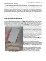
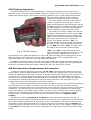
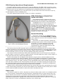
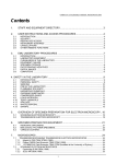
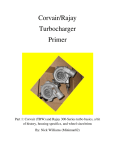
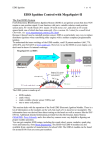
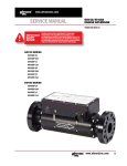
Oz DIY-WB and 5301 Display - P1
Oz DIY-wideband
and
TE-5301 display
User's manual
(rev. 0.0)
Tech Edge
Copyright © 2002 Tech Edge Pty. Ltd.
Introduction & History
Oz DIY-WB and 5301 Display - P2
The Oz DIY-WB unit and the supporting 5301 display are available as both a kit and as prebuilt
units from Tech Edge Pty. Ltd. The original DIY-WB design originated from quite a few
individuals whose aim it was to accurately measure AFR, with the ultimate goal of getting a better
tuned vehicle. An SAE paper indicated that there was an NTK sensor that Honda used in their
lean burn Civics in the early to mid 1990s. This sensor was found to be available at fairly low cost
compared to the cost of the same sensor when purchased with the very expensive AFR meters
that were available at the time. The DIY-WB goal was to produce a simple interface that used the
Honda/NTK Sensor, and which was fairly easy to build (simple design) but nonetheless accurate.
The Oz DIY-WB unit is a realisation of that design, and Tech Edge is proud to support the DIY
concept through the Oz DIY-WB as a kit and fully built unit.
The 5301 Display originated from a Silicon Chip magazine design for a narrow band oxygen
sensor interface that was readily modified for use with the DIY-WB. Tech Edge has refined the
original design and first offered it as the “Modified Jaycar 5300” kit, but demand was such that
we eventually redesigned the project to use a new PCB, and we called it the TE-5301 display.
Oz DIY Wideband Unit description
The Oz DIY wideband unit (called the DIY-WB, or simply the WB unit) comes in a tough
grey impact resistant ABS plastic case with different connectors at each end. One end (top of fig
1) has a circular 8 pin plug for connection to an NTK L1H1 oxygen sensor via a cable. The other
end has a 9 pin “D style” connector and a power cable to connect to the vehicle’s battery and
charging system. The D connector (called a DB9) carries the output voltage (Vout) from the unit
as well as power and ground for connection to the 5301 display or other display/logging device.
The WB unit’s power cable is wired to the target vehicle’s electrical system ground and
battery. The power side of the cable is identified
as the wire without any tracer and (normally)
with a small section of red (heatshrink) plastic
covering for positive identification. The ground
wire includes a tracer to distinguish it from the
power wire. It is very important that power and
ground to the WB unit is not reversed. The unit
has some protection circuitry to prevent damage
during normal operation, but these protection
devices will be damaged on power reversal, and
the WB unit will need some fairly low cost
electronic components replaced.
Fig 1. Oz DIY-WB unit
The WB unit has just a single red LED (Light
Emitting Diode) to indicate its operation. The
LED is lit when the WB unit is powered and the
sensor is up to temperature and the
battery/alternator is sufficient to keep the
sensor hot (see operational requirements
below). The LED will normally come on in 15 to
40 seconds after the vehicle has been started
and is warming up at either a fast idle or on the
road. On some vehicles, and with some sensor
placements, the LED may go out while the
vehicle idles, this normally indicates the
alternator voltage has dropped below the WB
unit’s operational point because of accessories
drawing power, an old battery, ineffective
alternator or charging system, or improper
connection of the WB unit to the vehicle.
Oz DIY-WB and 5301 Display - P3
5301 Display description
The 5301 display uses a 3 digit superbright 7 segment LED display used to show AFR (or
Lambda) and a 7 element vertical LED bar display to indicate rich or lean. At the top left of the
display face can be found a light sensing element (called an LDR or Light Dependant Resistor).
This is a safety measure so the display’s
brightness automatically dims in low light.
The 5301 display connects to the WB unit
using its (longer and thicker) grey 2 metre
cable which supplies it with both power and the
wideband signal. The display normally indicates
the AFR detected by the WB unit (although it
can be modified to read in Lambda units).
On powerup, the 5301 display will show the
7 segment representations of the letters “tE.c”
followed by the software version number (say
“11.c”) and will then continuously display the
AFR with a refresh rate of 2.5 times per
second. The display will show “14.7” (or
perhaps “14.6”) anytime the WB unit detects
the sensor is not up to operating temperature
(ie. the WB unit’s LED is OFF). At other times,
the display will show some value between
“10.1” and “24.9”. If the WB unit senses a
very rich mixture with AFR lower than 10.0 the
display will show “10.≤” where the “≤” is
represented on the rightmost display as a “5” or “S” with a missing lower right segment. If the
WB unit senses a very lean mixture it will display “25.≥” where “≥” is represented on the
rightmost display as a “3” with a missing lower right segment.
Fig 2. TE-5301 Display
The RS232 optioned version of the 5301 has a short cable with a DB9 connector that may be
connected to a PC or Palm device (with a serial adaptor) for data logging. See the specifications
section for information about the RS232 data that is sent out 5 times per second.
WB Unit Operational Requirements & Connection
The Oz DIY-WB unit requires a minimum of 13.2 Volts (measured at the battery end of the
power cable). Vehicle lead/acid batteries rated at 12 Volts will normally have too low a terminal
voltage to operate the unit unless the motor is actually running and charging to the nominal 13.8
Volt value for a correctly adjusted charging system. The DIY-WB unit should not normally be
connected to a cigarette lighter outlet because these connections are often fairly high resistance
and experience voltage drop sufficient to prevent proper operation. The best place is a preexisting high current relay operated by the ignition switch.
A fuse is a cheap and appropriate way to protect the WB unit and/or your vehicle from damage
should a fault occur in either. A 3 Amp (or at most a 5 Amp) in-line fuse should be directly
connected to the power cable (the wire without the tracer and with the short section of red plastic
heatshrink). The Ground wire (the wire with the tracer) should be connected to an earth point
close to the battery, preferably using a solder or crimp lug that is bolted to an existing earthing
chassis point. This earthing point should carry a wire going directly to the battery negative
terminal (note: all descriptions of power & ground connection assume a negative earth
system).
The WB unit draws a maximum of 1.5 Amps during sensor warm-up and as low as 1.0
Amps after both the exhaust system and sensor have warmed up. The WB unit’s red LED will not
be lit until the WB unit detects that the sensor is up to temperature. This LED will also go out if
the battery voltage falls below about 13.2 Volts during idle. If the sensor cable is removed (at
either the sensor or the WB unit end), the WB unit’s LED will come on at a battery voltage as low
as 11.5 Volts. Removing the 8 pin sensor connector is a good way to test that the WB unit has
power.
5301 Display Operational Requirements
Oz DIY-WB and 5301 Display - P4
The 5301 display normally gets its power from the WB unit. The DB9 (male connector on the
long cable) uses just three pins for power, ground and wideband signal. If you closely inspect the
connector itself, you will identify the numbering there to determine which pin is which.
The power is applied to pin 9, Ground to pin 6 (on the other side of the connector to pin 9),
and the signal is on pin 7 (beside pin 6).
The 5301 display draws less than a tenth of an Amp in operation.
NTK L1H1 Sensor (Honda Part
36531-P07-003)
The wideband sensor measures AFR, when
used with the DIY-WB interface, by sensing the
partial pressure of oxygen in the exhaust gas.
The L1H1 sensor is vital to the operation of
the DIY-WB unit and is made by NTK but is
normally sold as an aftermarket part and may be
packaged as a Bosch, Echlin, etc. part. The Parts
Bin (part C5010-75044), Napa Online (part
ECHOS791), Honda (part 36531-P07-003),
and others sell the sensor, but due to the high
demand, are often out of stock.
Sensor Mounting
The sensor screws into an 18 mm diameter
hole with a pitch of 1.5 mm/thread. A 22 mm
(7/8”) spanner secures it into a standard oxygen
sensor bung.
The sensor can often physically replace the
existing oxygen sensor, but for proper operation
of the ECU, it is often desirable to provide
Fig 3. NTK L1H1 Wideband Sensor
another bung for the wideband sensor. We
recommend you place the NTK sensor a little
downstream of the existing sensor, and certainly before the catalytic converter.
The sensor should not be mounted with its wires pointing downward as this can allow water,
that may condense on the inside of the sensor’s body during warmup, to drip onto and crack the
ceramic heater element inside the sensor’s body. Always mount the sensor 15 degrees or more
to the horizontal (in the 10 to the 2 o’clock position with wires at the top).
The sensor wires are made from Teflon with a stainless steel core, but ensure the connector
and the cable it connects to (which is made from PVC covered copper wire with a nylon sheath) is
kept right away from any vehicle heat above 80˚C.
Some tuning shops use an adaptor that holds the oxygen sensor, and this adaptor is then
secured to the end of the vehicle’s tailpipe. This position is not recommended for vehicles with a
catalytic converter as the converter will change the readings you are measuring (that’s the cat’s
main function in life!). For carby vehicles (or non-operational cats on EFI vehicles) this position
may also be a problem as the exhaust gasses can be quite cool after travelling the length of the
car, and the sensors heater may have to work too hard to maintain an operational temperature.
Serious tuning will require a hotter position closer to the manifold.
Vehicles with a turbocharger should position the sensor after the turbo (and before the cat) as
a high exhaust back pressure (as will be found between the manifold and the turbo) has an effect
on the measured AFR and tends to read richer than is actually the case.
Sensor Life
The sensor is rated for a life of 160,000 km (100,000 miles) when used in an unleaded vehicle
but can be quickly contaminated by lead and other compounds found in some racing fuels. The
sensor should never be left in an exhaust stream without power to the heater circuit as this will
rapidly gum up the internal components with carbon that is otherwise burnt off at normal
operational temperatures. Ageing of the sensor tends to produce a slower response to changing
AFRs, and this is a way to qualitatively determine your sensors age.
Oz DIY-WB and 5301 Display - P5
It is recommended to shroud the sensor when using fuels that create high levels of particulate
matter (including lead and carbon) in an attempt to prevent particles entering the sensor’s
diffusion chamber and thus blocking it and slowing its response.
Sensor calibration
Calibration of individual sensors is not required as a calibration
resistor (Rcal in the image – the resistor is hidden inside the
connector housing) is provided by the factory in each sensor’s grey
connector shell. Two extra pins inside the cable to the sensor are
used to connect Rcal to the WB unit.
It is possible to check the calibration of the sensor by measuring
the WB unit’s free-air Vout. This is the Vout obtained when the
sensor has been sitting in free-air for a period of a minute or so, and
has stabilised. The ideal free-air Vout is 4.00 Volts, but this may vary
from unit to unit and sensor to sensor. It is possible to replace the
factory supplied calibration resistor in order to improve the freeair calibration. We believe the standard WB unit will be accurate
enough for most users without having to do this.
Fig 4. L1H1 Sensor ‘s
Connector (Sumitomo)
WB Unit to Sensor Cable
The standard cable lengths that may be suppled with the Oz
DIY-WB unit are 2.6 metres (about 8.5 feet) and 4.0 metres
(about 13 feet). The cable lengths are approximate, and will
typically be slightly longer.
The cable has a circular connector at one end that allows it
to be readily passed through the firewall of most vehicles. An
18 mm hole (just less than ¾ inch), is required and should
include a grommet or other device to prevent chafing against
any sharp edges of the hole.
The complete cable is made up from a heavy duty figure 8
cable used to supply heater power to the sensor, and a 4 core
shielded light gauge cable for the sensor signals. Both
individual cables are enclosed in a tough braided black nylon
sheath.
Fig 5. WB Unit to L1H1
sensor Cable
The cable must be protected from sources of radiant heat
such as exhaust manifolds, and should be routed to the WB
unit using the shortest path that keeps the cable as far as
possible from the engine itself.
The same colour coding scheme is use on the WB cable as is
used on the NTK sensor itself. The following table shows the
pinouts of the sensor and the pins used on the circular 8 pin
connector (CON1).
Figure 6 shows the pinouts of CON1 as seen by a person looking at the end of the WB unit.
Function
CON1
L1H1 Wire
Vs (Vnb sense)
1
Red
Vs/Ip (common)
2
Black
Ip (Pump current)
3
White
Rcal -
4
-
Rcal +
5
-
Heater -
6
Yellow
Heater +
7
Orange
Fig 6. CON1 - looking
at the WB unit.
Vout Specifications. Lambda, and AFR
Oz DIY-WB and 5301 Display - P6
First some definitions - The stoichiometric point is where all the available oxygen has
combined with all the available fuel leaving no free residual oxygen.
AFR is the ratio of the quantity of air versus the quantity of fuel used at any instant.
Lambda is a ratio of
ratios and is equal to the
current AFR divided by the
stoichiometric AFR, and is
1.0 exactly at the
stoichiometric point for any
given fuel.
The Vout signal (pin 7 of
WB unit’s DB9 connector) is
converted to lambda using
the graph at right. The
lambda measure is
independent of the
hydrocarbon fuel being used.
The stoichiometric point is
shown on the graph as the
bold vertical line at lambda
of 1.000.
The DIY-WB stoichiometric
output voltage is nominally 2.50 Volts and
crosses the bold vertical line
at a lambda of 1.000.
Vout
The table at right shows the
1.40
approximate AFRs for a
1.45
number different common
1.50
fuels (petrol is also known as
1.55
“gas” in North America, or just
1.60
unleaded. LPG is Liquid
1.65
Petroleum Gas).
1.70
As fuel compositions are
1.75
seasonal and regional, the
1.80
AFRs shown here should be
1.85
considered only as approx1.90
imate. The 5301 display has
1.95
an internal look-up table and
2.00
displays the “Petrol” column
2.05
for any given Vout input. This
2.10
table may be used to convert
2.15
the 5301’s displayed (petrol)
2.20
value into an AFR for say LPG.
2.25
Alternatively, if you have
2.30
logged Vout somehow, this
2.35
table can be used to convert
2.40
to the AFR for your particular
2.45
fuel.
2.50
The stoic Vout is nominally
2.55
2.50 Volts, but can be as high
2.60
as 2.53 and as low as 2.47.
2.65
The figures presented here
2.70
assume the calibration resistor
2.75
supplied in the L1H1 sensor’s
2.80
connector produces a free-air
2.85
Vout of 4.00 Volts.
2.90
this point is shown as the bold horizontal line that
Lambda
0.686
0.696
0.706
0.716
0.727
0.739
0.750
0.762
0.774
0.787
0.800
0.814
0.828
0.842
0.857
0.873
0.889
0.905
0.923
0.941
0.960
0.980
1.000
1.037
1.078
1.121
1.169
1.220
1.276
1.337
1.405
Petrol
10.08
10.23
10.38
10.53
10.69
10.86
11.03
11.20
11.38
11.57
11.76
11.96
12.17
12.38
12.60
12.83
13.07
13.31
13.57
13.84
14.11
14.40
14.70
15.25
15.84
16.48
17.18
17.93
18.76
19.66
20.66
LPG
10.63
10.79
10.94
11.10
11.27
11.45
11.63
11.81
12.00
12.20
12.40
12.61
12.83
13.05
13.29
13.53
13.78
14.03
14.31
14.59
14.88
15.18
15.50
16.08
16.70
17.38
18.11
18.91
19.78
20.73
21.78
Ethanol
4.39
4.45
4.52
4.58
4.65
4.73
4.80
4.88
4.95
5.04
5.12
5.21
5.30
5.39
5.49
5.59
5.69
5.79
5.91
6.03
6.14
6.27
6.40
6.64
6.90
7.17
7.48
7.81
8.17
8.56
8.99
Diesel
9.94
10.09
10.24
10.39
10.54
10.71
10.88
11.05
11.23
11.41
11.60
11.80
12.00
12.21
12.43
12.66
12.89
13.13
13.39
13.65
13.92
14.20
14.50
15.04
15.62
16.26
16.95
17.69
18.50
19.39
20.38
Oz DIY-WB and 5301 Display - P7
Wiring and Connector Diagrams
The three connection points to the WB unit are represented above as CON1 (the circular 8 pin
connector, on the left), CON2 (the DB9, on the right), and CON3 (the two wires coming directly
from the WB unit). The 5301 display is represented as the box showing 14.7 above. The display
is connected to the WB unit with a long (2 metre) cable, and a short cable from the display
carries the RS232 data.