1
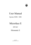
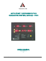
S. & A.S. LTD
AUTO START / INSTRUMENTATION
GENERATOR CONTROL MODULE – PVS1
USER’S MANUAL
FOR H/W VERSION 1.34
FOR S/W VERSION 2.30
0846
BOUTROS BLDG, 1st BSMT
CHEIKH-EL-GHABY ST.
GHABY – BEIRUT
Postal Code 2068 7808
TEL 01 – 216994
FAX 01 - 339600
-21
2
3
4
INTRODUCTION......................................................................................................................................................3
FEATURES ..............................................................................................................................................................3
OPERATION ............................................................................................................................................................3
VIEWING FAULTS AND FAULTS DESCRIPTION ................................................................................................4
4.1
HOW TO VIEW THE FAULTS ........................................................................................................................4
4.2
HOW TO ERASE THE FAULTS .....................................................................................................................4
5
FRONT PANEL DESCRIPTION..............................................................................................................................4
5.1
MEASURED AND DISPLAYED PARAMETERS ...........................................................................................4
5.2
FRONT PANEL LEDS.....................................................................................................................................4
5.3
DETECTED AND SIGNALED FAULTS..........................................................................................................5
5.4
DESCRIPTION OF STATUS MESSAGES SHOWN ON MULTIFUNCTION DISPLAY................................5
6
REAR PANEL DESCRIPTION................................................................................................................................6
6.1
TERMINAL DESCRIPTION.............................................................................................................................6
6.2
LEDS DESCRIPTION......................................................................................................................................7
7
FEATURES SUPPORTED BY DIRECT RS232, MODEM CONNECTION OR ETHERNET ................................7
7.1
SETTING UP THE PVS1 FOR GSM MODEM................................................................................................8
7.2
SETTING UP THE PVS1 FOR ETHERNET ...................................................................................................9
8
MENU DESCRIPTION ...........................................................................................................................................10
9
TECHNICAL SPECIFICATION .............................................................................................................................11
10 CASE DIMENSIONS .............................................................................................................................................12
11 TYPICAL WIRING DIAGRAM ...............................................................................................................................12
-31
INTRODUCTION
This module is the first in a new generation of smart microcontroller based, integrated and low cost
generating set controllers. It features enhanced automatic starting and stopping, protection of both engine and
generator in addition to instrumentation. A four-position selector provides multiple operating modes:
OFF/RESET, AUTO, RUN and TEST. Front panel leds signal the genset status in addition to the faults. The
instrumentation interface consists of six 7-segments led displays, size 0.4” and is used to display the currents
on the three phases, the voltage and the frequency simultaneously. The fifth display is multifunction and is used
to display the active power in KW, the hour meter, the oil pressure, the engine temperature, the genset status,
the battery voltage and the fault log. Three front panel push buttons are provided to select the voltage, to
access a menu of parameters, to view the last fault with its correspondent readings and to switch to measured
values to be displayed on the multifunction display. The menu gives access to all timers, set points and other
parameters relevant to the control and protection of the genset. This module can be remotely monitored via
connection to Ethernet, a line modem or a GSM modem.
2
FEATURES
•
•
•
•
•
•
•
•
•
•
•
•
•
•
•
•
•
•
•
•
•
•
•
3
Microcontroller based design
Operation by a 4-position selector switch
Easy to fit DIN standard 196x144 panel mount housing
Connection is via locking plug and socket connectors
Three dedicated current displays for the three lines
Dedicated voltage display with push buttons to scroll down all six voltages
Dedicated frequency display
Multifunction 6-digits 7-segment display
Front panel leds for status and alarm indication
Automatic engine starting and stopping
Automatic shutdown on fault condition
Magnetic pick-up input for measuring frequency
Coolant level sensing by an ac current to avoid electrolysis of the radiator probe
Menu to provide access to all timers, set points and other parameters
Over / Under speed alarm and shut down
Over / Under voltage alarm and shut down
Overload alarm and shut down
Low oil pressure pre-alarm
Low oil pressure alarm and shut down
High temperature pre-alarm
High temperature alarm and shut down
High / Low battery voltage alarm and shut down
Lamp (led) test by pressing both Up and Down buttons
OPERATION
Four operating modes are provided:
•
•
•
•
1
OFF/RESET: In this mode the module is completely off and no current is drawn from the battery. If the
engine was running prior to switching to this mode, it will be shut down along with the load contactor
immediately.
RUN: In this mode the module starts the engine and engages the load after warm-up delay. If this mode
is selected after TEST mode, the module re-engages the load after warm-up delay.
TEST: Load contactor is released immediately and the genset is kept running at no load. Of course,
switching to this mode from OFF/RESET will prompt the module to start the genset and run it at no
load.
AUTO: The module starts the genset after a response delay1 if a start signal is received on the remote
control input. Load is engaged after the elapse of the warm-up delay2. When the start signal is
removed, the load contactor is released after an off delay3 and the genset is shut down after the elapse
of the cooling time4.
Response delay is set by selecting item A01 in the menu. Refer to section 6.
Warm-up delay is set by selecting item A07 in the menu. Refer to section 6.
Off delay is set by selecting item A08 in the menu. Refer to section 6.
4
Cooling time is set by selecting item A09 in the menu. Refer to section 6.
2
3
-4-
Crank disconnect is exclusively based on the frequency if the magnetic pick-up is installed. The
frequency set point used to stop cranking is set by item A12 in the menu; refer to section 6. On the other hand,
if the magnetic pick-up is not installed, crank disconnect is based on the oil pressure switch as well as the
generator frequency. Furthermore, only the frequency display remains on during cranking.
The displays remain on as long as the engine is running. When the engine stops all displays will go off
after a delay of 25 sec to preserve battery power.
4
VIEWING FAULTS AND FAULTS DESCRIPTION
4.1
HOW TO VIEW THE FAULTS
Pressing the Enter push button while “FLtLog” is displayed on the multifunction display will prompt the
PVS1 to start displaying the last 10 faults saved in memory. The PVS1 begins by displaying the last fault on the
multifunction display. Press Previous or Next push buttons to display the previous or next fault. To view the
voltage, current, frequency and other parameters of the multifunction display saved when the fault has
occurred, press Enter. Previous or Next will scroll down the parameter displayed on the multifunction display.
When Enter is pressed again, all the displays return to their actual reading and the multifunction display shows
the fault code. To exit the fault log, Press Previous or Next until “NoErr” is displayed.
4.2
HOW TO ERASE THE FAULTS
To erase the faults, enter the menu, go to A36 and press Enter push button. You will be prompted to
confirm your request. If Enter is pressed all faults are erased, if Previous or Next are pressed, faults will not be
affected.
5
FRONT PANEL DESCRIPTION
5.1
MEASURED AND DISPLAYED PARAMETERS
•
•
•
•
•
•
•
•
•
The currents on the three phases are measured and displayed simultaneously.
The line-neutral and line-line voltages are all measured. The voltage displayed is selected by the up
and down push buttons.
The frequency1 is measured and permanently displayed.
The active power in KW is measured and displayed on the multifunction display.
The hour counter is updated and displayed on the multifunction display.
The oil pressure is measured and displayed on the multifunction display.
The engine temperature is measured and displayed on the multifunction display.
The battery voltage is measured and displayed on the multifunction display.
A fault description is showed on the multifunction display upon the occurrence of any fault.
Pushing the increase and decrease push buttons simultaneously activates a lamp test and switches their
function between the voltage display and the multifunction display.
5.2
FRONT PANEL LEDS
•
•
•
•
•
•
•
•
•
•
•
1
Start / run: ON indicates reception of a starting command. Blinking indicates that the engine is running
Engaged
Fail: ON indicates a failure to start or a magnetic pick-up failure. Blinking indicates an emergency stop,
a high battery voltage or a low battery voltage.
Low oil pressure
High temperature
High oil temperature
Over/under speed (led blinks for over speed and remains ON for under speed)
Low coolant
Overload
Over/under voltage (led blinks for over voltage and remains ON for under voltage)
Spare 2/Spare 1
The frequency is based on the RPM read from the magnetic pick-up if installed; otherwise it will be based on the generator output
voltage.
-55.3
DETECTED AND SIGNALED FAULTS
ALARM
RELAY
SHUT
DOWN
>
>
>
>
>
>
>
>
>
>
>
>
High Temperature
>
>
High oil Temperature
>
>
Over/Under speed
Low Coolant Level
Over/Under Voltage
>
>
>
>
>
>
Overload
>
>
Spare1
>
>
Spare2
>
>
Fault
Fail to start
Emergency stop
High battery voltage
Low battery voltage
Magnetic pick-up
Low oil Pressure
5.4
Comments
Fail led ON
Fail led blinking
Shuts load and engine after high battery voltage delay.
Shuts load and engine after low battery voltage delay.
Fail led ON
Immediate visual alarm. Shuts load and engine down 5 sec after alarm
Immediate visual alarm. Shuts load 4 sec after alarm and engine after
1
cooling
Immediate visual alarm. Shuts load 4 sec after alarm and engine after
cooling2
3
Immediate visual alarm. Shuts load and engine down after 1.5/5 sec delay
Shuts load and engine down 4 sec after alarm
4
Immediate visual alarm. Shuts load and engine down after 3/5 sec delay
Immediate visual alarm. Shuts load after overload delay. Shuts engine after
5
cooling
Immediate visual alarm. Shuts load and engine down 4 sec after alarm.
Spare led ON
Immediate visual alarm. Shuts load and engine down 4 sec after alarm.
Spare led blinking
DESCRIPTION OF STATUS MESSAGES SHOWN ON MULTIFUNCTION DISPLAY
Status Message
Rdy
rtS
PHt
CrA
Run
rLd
SLd
SEg
StFAiL
LoOiLP
Hi °C
S1FAiL
S2FAiL
HiUoLt
LoUoLt
HiFrEq
LoFrEq
HiLoAd
HiOiLt
PiFAiL
LoCooL
E StoP
Hi bAt
Lo bAt
1
2
3
4
5
Description
Genset ready
Request to start with countdown of response delay
Preheating with countdown of preheating delay
Cranking
Engine running with countdown until load is engaged
Engine running on load
Counting down off delay time to disconnect the load
Counting down cooling time to shut down the engine
Fail to start
Low oil pressure
High temperature
Spare1 fail
Spare2 fail
Overvoltage
Undervoltage
Overspeed
Underspeed
Overload
High oil temperature
Magnetic pick-up fail
Low coolant level
Emergency stop
High battery voltage
Low battery voltage
If A20 is not set to zero. Otherwise, engine is shut with alarm.
If A20 is not set to zero. Otherwise, engine is shut with alarm.
If either A10 or A11 parameter is set to zero its correspondent alarm is disabled.
If either A13 or A14 parameter is set to zero its correspondent alarm is disabled.
If A20 is not set to zero. Otherwise, engine is shut with alarm.
-66
6.1
REAR PANEL DESCRIPTION
TERMINAL DESCRIPTION
The following tables summarize the terminals functions of each of the 7 connectors.
CONNECTOR
P1
1
TERMINAL
2
-VBAT
SUP
+VBAT
SUP
P2
-ve battery supply
7
ALARM
NC
+ve battery supply
8
ALARM
NO
Output for alarm normally opened
Output for alarm normally closed
3
PRE
HEAT
Output for preheating resistor
9
COIL
C
Output for load contactor common
4
ELEC.
VALVE
Output for fuel electric valve
10
COIL
NO
Output for load contactor normally
opened
5
START
Output for starter
11
TRIP
C
Spare output common
6
ALARM
C
Output for alarm common
12
TRIP
NO
Spare output normally opened
CONNECTOR
TERMINAL
P3
13
DYNA
EXCT
14
+VBAT
POWER
15
RMTE
CNRL
16
P4
SPARE
Dynamo excitation output
19
After emergency stop and fuse
20
Remote control input
21
NOT
USED
OPS
Oil pressure switch input
22
COOL
PROBE
17
ETS
Engine temperature switch input
23
PICK
UP-
Magnetic pick-up –ve input
18
OTS
Oil temperature switch input
24
PICK
UP+
Magnetic pick-up +ve input
1
SPARE
2
Spare 1 input
Spare 2 input
Not used
Radiator coolant level sensing
probe
CONNECTOR
TERMINAL
P5
25
CT R
P1
Current transformer on line R – p1
26
CT R
P2
27
31
Line R input
Current transformer on line R – p2
32
NOT
USED
Not used
CT S
P1
Current transformer on line S – p1
33
LINE
S
Line S input
28
CT S
P2
Current transformer on line S – p2
34
NOT
USED
Not used
29
CT T
P1
Current transformer on line T – p1
35
LINE
T
Line T input
30
CT T
P2
Current transformer on line T – p2
36
N
Neutral input
CONNECTOR
P7
TERMINAL
P6
LINE
R
37
ET
SENS
Engine temperature sensor input
38
OP
SENS
Oil pressure sensor input
39
COM
Sensors common input
-76.2
LEDS DESCRIPTION
The rear panel leds signal the status of the digital inputs:
Led No.
1
2
3
4
5
6
7
Color
Green
Red
Red
Red
Red
Red
Correspondent input
Remote control input
Oil pressure switch input
Engine temperature switch input
Oil temperature switch input
Spare 1 input
Spare 2 input
FEATURES SUPPORTED BY DIRECT RS232, MODEM CONNECTION OR ETHERNET
Through direct RS232 to a PC, a line modem, a GSM modem or an Ethernet connection, the user will be
connected to the PVS1. When connection is established, the following window appears:
-8The user will be able to view the following:
1.
2.
3.
4.
5.
6.
7.
8.
9.
10.
11.
12.
13.
14.
15.
Selected voltage.
Frequency.
Three phases' currents.
Oil pressure.
Temperature.
Battery voltage.
Power in KW.
Hour meter.
Over/under voltage set point.
Over/under frequency set point.
Overload set point.
Over/under battery voltage set point.
Generator status.
Communication status.
The 10 recent faults with all their corresponding readings by pressing the "View Faults" button.
In addition to the above, the user has access to the following:
1.
2.
3.
4.
5.
6.
7.1
Run the PVS1 with or without load by pressing “Run” or “Test” button.
Stop the PVS1 by pressing “Stop” button. This button cancels the Run/Test order.
Clear the fault log by pressing "Erase Faults" button in the “View Faults” window.
View and modify the parameters using "Edit Parameters".
Reset the PVS1 module by pressing "Reset Module" button.
Collect data with a fixed sampling interval by pressing “Start Sampling” button.
SETTING UP THE PVS1 FOR GSM MODEM
Please set the following parameters to be able to use the GSM modem:
1. The identification of the PVS1 module: This ID will be included as a header of all sent or received SMS
messages. It must contain 6 digits which can be numbers (from 0 to 9) combined with the following
letters: a, b, c, d, e, f, h, i, l, n, o, p, q, r, s, t, u, y (upper or lower case, e.g. SASt09). Any message with
a wrong ID will be ignored.
2. The phone number: When a fault occurs, The PVS1 will send an SMS containing as a header the
PVS1 ID followed by the fault description and all the readings at the time the fault occurred. This SMS
is sent to the phone number specified by the user. The phone number must be between 3 to 18 digits
long.
Following is a description of the functions supported via SMS:
Reset
Run
Test
Stop
View all the readings
Modify
the
View thet parameters
PVS1 ###### reset1
PVS1 ###### run
PVS1 ###### test
PVS1 ###### stop
PVS1 ###### measure
PVS1 ###### modify A01=5,A03=32,A12=145,A30=0,A10=232
PVS1 ###### request A01,A03,A12,A30,A103
1
###### being the ID number.
A maximum of five parameters can be modified in the same message. All parameters are accessible except the ID, the phone
number, the hour meter and the PC/Modem/GSM modem selection.
2
3
A maximum of five parameters can be requested in the same message.
-97.2
SETTING UP THE PVS1 FOR ETHERNET
How to set the PVS1 IP address:
9
9
Enter the menu (Refer to PVS1 v1.34 manual, section 8)
Go to item labeled A33:
¾ If dynamic IP is used, enter the digit “1” followed by the digit “b”(e.g. 1b)
¾ If fixed IP is used, enter the digit “0” followed by 12 digits representing the IP address .Then enter
the subnet mask which is a two digit number followed with the digit ”b” (e.g. 019216800002408b)
¾ Go to A34 (optional) to enter a name that refers to the site where the PVS1 is installed.
-108
MENU DESCRIPTION
Follow the steps described below to access the menu:
1. While module is powered, press the ENTER push button once. You will be prompted to enter a threedigit code on the voltage display. Display shows “E“ on the leftmost digit.
2. Use the UP and DOWN push buttons to scroll to the desired number.
3. Press the ENTER push button. “c” replaces the first digit. “E” is displayed on the middle digit.
4. Use the UP and DOWN push buttons to scroll to the desired number.
5. Press the ENTER push button. “c” replaces the middle digit. “E” is displayed on the rightmost digit.
6. Use the UP and DOWN push buttons to scroll to the desired number. Press the ENTER push button.
If the entered password is valid, the user will have access to the menu below. If no push buttons are pressed for
25 sec while in the menu, the system will automatically exit the menu.
Display
A01
A02
A03
A04
A05
A06
A07
A08
A09
A10
A11
A12
A13
A14
A15
A16
A17
A18
A19
A20
Parameter description
Response delay
Pre-heater time
Starter time
Time between trials
Number of attempts
Fault bypass delay
Engine warm-up time
Off delay time
Engine cooling time
Over frequency set point
Under frequency set point
Crank disconnect frequency
Over voltage set point
Under voltage set point
Current transformer ratio /10
Overload in % of current transformer
Overload delay
Range
0 to 255sec
0 to 255sec
0 to 255sec
0 to 255sec
0 to 255
0 to 255sec
0 to 255sec
0 to 255sec
0 to 255sec
0 to 255Hz
0 to 255Hz
0 to 255Hz
0 to 255V
0 to 255V
0 to 255
0 to 255
0 to 255sec
Flywheel count of teeth per revolution
0 =magnetic pick-up not installed
1-255= enables magnetic pick-up
and sets the flywheel count of
teeth
Coolant level float switch / Spare 1
input logic
Cooling after high temperature, high oil
temperature and overload alarm
A21
Oil pressure sensor type
A22
Engine temperature sensor type
A24
A25
A26
A27
A28
A29
A30
A31
Oil pressure bypass delay for crank
disconnect/10
Low oil pressure pre-alarm set point
Low oil pressure shut down set point
High temperature pre-alarm set point
High temperature shut down set point
High battery set point
Low battery set point
High battery delay
Low battery delay
A32
Regular Modem/GSM/PC selection
A33
A34
A35
A36
A37
Phone number
PVS1 ID
Modify hour meter
Erase Faults
Exit Menu
A23
0=nc/nc 1=nc/no
2=no/nc 3=no/no
0=no cooling before shutdown
1-255= cooling before shutdown
0=VDO
1=ECHLIN
2=MURPHY
0=VDO-1
1=VDO-2
2=MURPHY
0 to 255
0=disabled
1 to 255psi
0=disabled
1 to 255psi
0=disabled
1 to 255degreeC
0=disabled
1 to 255degreeC
0 to 255V
0 to 255V
0 to 255sec
0 to 255sec
0 for Regular Modem/
1 for GSM/ 2 to 255 for PC
3 to 18 digits long
######
0 to 99999
N/A
N/A
Factory setting
5 sec
0 sec
5 sec
12 sec
3
15 sec
10 sec
10 sec
5 sec
55Hz
45Hz
15Hz
240V
200V
10
90
10 sec
0
3
1
0
0
0.0sec
0
0
0
0
30V
8V
3sec
2sec
255
000000000000000000
SAStSt
0
N/A
N/A
-119
TECHNICAL SPECIFICATION
Supply voltage range
Maximum supply current
1
Standby supply current
Digital inputs activation logic
Output relays rating
AC inputs range (L-N)
CT inputs range
Operating temperature
User access
Data sampling rate
Dimensions
1
5 to 33Vdc
550mA on 12Vdc – 275mA on 24Vdc
60mA on 12Vdc – 30mA on 24Vdc
Low (ground)
10A 250V ac1
0 to 280Vac
0 to 5Amps
-30 to 70°C
Three touch buttons
0.8 samples/sec
192x144x78
In AUTO mode with genset in standby and waiting for a start signal.
-1210
CASE DIMENSIONS
11
TYPICAL WIRING DIAGRAM
GROUND SHIELD AT ONE END ONLY
PICK-UP
TEMP. SENSOR
OIL P. SENSOR
23
24
37 38
39
31
33
35
36
25
26
27
28
29
30
ALARM
1
2
14
FUSE
EMERGENCY
STOP
DYNAMO
R
S T N
LOAD
3
4
5
6
7
8
15
16
17
18
19
20
22
COIL
9
10 11 12
13