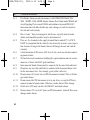
1
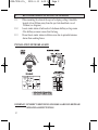
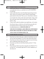
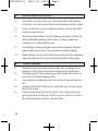
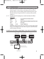
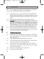
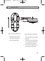
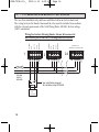
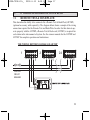
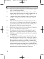
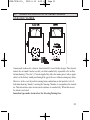
1398-7208-03:_
2012.6.13
4:24 PM
Page 1
MODEL LIF5800 & LIF5800RL
INSTALLATION AND USER MANUAL
LIFESAVER SMOKE ALARM PHOTOELECTRIC DESIGN
240VAC MAINS POWERED SINGLE STATION AND/OR INTERCONNECTABLE
(24 UNITS) PHOTOELECTRIC SMOKE ALARM. 9V REPLACEABLE BATTERY
BACKUP (MODEL LIF5800) OR BUILT-IN RECHARGEABLE BATTERY BACKUP
(MODEL LIF5800RL). TEST AND HUSH CONTROL AND LOW BATTERY
INDICATION.
IMPORTANT: READ ALL INSTRUCTIONS BEFORE INSTALLATION.
NO USER REPLACEABLE PARTS INSIDE THIS SMOKE ALARM.
WARNING: Disconnecting smoke alarm from mounting base and/or removing the 9V battery
will render this smoke alarm inactive.
SPECIFICATION
ELECTRICAL RATING:
240VAC 50Hz, 80mA per alarm and interconnectable to
24 alarms.
WARNING: THIS SMOKE ALARM MUST ONLY BE WIRED TO A
240Vac 50Hz SINE WAVE CURRENT SUPPLY.
THIS PHOTOELECTRIC SMOKE ALARM CONTAINS NO RADIOACTIVE
MATERIALS
1398-7208-03:_
2012.6.13
4:24 PM
Page 2
CONTENTS
RECOMMENDED LOCATIONS OF ALARMS ................................................................................1
MOBILE HOME INSTALLATION.................................................................................................................3
AVOID THESE LOCATIONS............................................................................................................................. 3
FALSE ALARMS.............................................................................................................................................................4
HOW TO REMOVE SMOKE ALARM FROM BASE PLATE..............................................5
INSTALLATION...............................................................................................................................................................5
OPERATION, TESTING AND MAINTENANCE..........................................................................10
BATTERY INSTALLATION, REPLACEMENT AND TEST..............................................13
9V TERMINAL AND REMOTE TEST & HUSH............................................................................15
REPAIRS AND SERVICES.................................................................................................................................19
GOOD SAFETY HABITS.....................................................................................................................................19
THE LIMITATIONS OF SMOKE ALARMS.......................................................................................19
OPERATING PRINCIPLES OF SMOKE ALARMS....................................................................21
DEVELOP AND PRACTICE A PLAN OF ESCAPE...................................................................22
WHAT TO DO WHEN THE ALARM SOUNDS.............................................................................23
INSTALLER PLEASE NOTE...........................................................................................................................24
WARNING: INSULATION TEST.................................................................................................................24
WARRANTY AND LIABILITY.....................................................................................................................25
1398-7208-03:_
1.
1.1
1.2
1.3
1.4
1.5
1.6
1.7
1.8
1.9
1.10
2012.6.13
4:24 PM
Page 1
RECOMMENDED LOCATIONS OF ALARMS
Locate an alarm for each separate sleeping area in the immediate vicinity of
the bedrooms. Try to monitor the exit path as the bedrooms are usually farthest from an exit. If more than one sleeping area exit, locate additional
alarms in each sleeping area in the immediate vicinity bedrooms.
Locate additional alarms to MONITOR any stairway as stairways act like
chimneys for smoke and heat.
Locate at least one alarm on every floor level.
Locate an alarm in every room where a smoker sleeps.
Locate an alarm in every room where electrical appliances are operated (i.e.
portable heaters or humidifiers).
Locate an alarm in every room where someone sleeps with the door closed.
The closed door may prevent an alarm not located in that room from waking
the sleeper.
Smoke, heat and other combustion products rise to the ceiling and spread
horizontally. Mounting the alarm on the ceiling in the center of the room
places it closest to all points in the room. Ceiling mounting is preferred in ordinary residential construction.
For mobile home installation select location carefully to avoid thermal barrier that may form at the ceiling. For more details see Mobile Home Installation (Section 2).
When mounting alarms on the ceiling locate it at least 300mm away from the
side wall and 300mm away from any corner. (see diagram)
When mounting alarms on a wall, use the inside wall. The recommended position is between 300mm and 500mm off the ceiling. (see diagram)
NOTE: The performance of smoke alarms mounted on walls is unpredictable
and this mounting position is not recommended when ceiling mounting can be
implemented.
1
1398-7208-03:_
1.
1.11
1.12
1.13
2012.6.13
4:24 PM
Page 2
RECOMMENDED LOCATIONS OF ALARMS
When mounting the alarm at the apex of a sloping ceiling it should be
located at least 500mm away from the apex but should not exceed
1500mm (see diagram).
Locate smoke alarm at both ends of a bedroom hallway or large room
if the hallway or room is more than 9m long.
Do not locate smoke alarms in kitchen areas due to potential nuisance
alarms from cooking fumes.
INSTALLATION OF SMOKE ALARM
IMPORTANT: INCORRECT ORIENTATION OF SMOKE ALARM MAY DECREASE
OPERATIONAL EFFECTIVENESS
2
1398-7208-03:_
2.
2.1
2.2
2.3
2012.6.13
4:24 PM
Page 3
MOBILE HOME INSTALLATION
Modern mobile homes have been designed and insulated to be energy efficient. Install smoke alarms as recommended (refer to RECOMMENDED
LOCATIONS).
In older mobile homes that are not well insulated compared to present standards, extreme heat or cold can be transferred from the outside through
poorly insulated walls and roof. This may create a thermal barrier which can
prevent smoke from reaching a smoke alarm mounted on the ceiling. In such
units, install smoke alarm on inside partition between 300mm and 500mm
from the ceiling.
If you are not sure about the insulation in your mobile home, or if you notice
the walls and ceilings are either hot or cold, install alarm on an inside wall.
For minimum protection, install one alarm close to the bedrooms.
For additional protection, see SINGLE FLOOR PLAN.
NOTE:TEST YOUR SMOKE ALARM OPERATION AFTER MOBILE
HOME VEHICLE HAS BEEN IN STORAGE, BEFORE EACH TRIP
AND AT LEAST ONCE WEEK DURING USE.
3.
AVOID THESE LOCATIONS
3.1
Do not locate your alarm in the garage - products of combustion are present
when you start your automobile. Use Lifesaver Heat Alarm in this location.
Do not locate your alarm in front of forced air supply ducts used for heating
and air conditioning and other high air flow areas.
Do not locate your alarm less than 500mm from the peak of an "A" frame
type ceiling.
Do not locate your alarm in areas where temperatures may fall below 5°C or
rise above 45°C, or in humidity higher than 85% as these conditions may reduce battery life.
3.2
3.3
3.4
3
1398-7208-03:_
3.
3.5
3.6
3.7
3.8
3.9
3.10
4.
4.1
4.2
4.3
4.4
4.5
4
2012.6.13
4:24 PM
Page 4
AVOID THESE LOCATIONS
Avoid dusty areas, dust particles may cause smoke alarm to false alarm or
fail to alarm. Use Lifesaver Heat Alarm in this location to avoid false alarms.
Avoid very humid areas or near a bathroom, moisture can cause false alarm.
Avoid insect-infested areas.
Do not locate alarm within 0.9m of the following: the door to a kitchen, the
door to a bathroom containing a tub or shower, ceiling or whole house
ventilating fans, or other high flow areas.
Avoid locating near fluorescent lights or other electrical equipment. Electronic
magnetic interferences or “noise” may cause nuisance alarms or chirping.
Smoke alarms are not to be used with detector guards unless the combination
(alarm and guard) has been evaluated and found suitable for that purpose.
FALSE ALARMS
This smoke alarm is designed to minimize false alarms. Smoking will not
normally set off the alarm unless smoke is blown directly into the alarm.
Combustion particles from cooking may set off the alarm if the alarm is located close to the kitchen cooking surface.
Large quantities of combustion particles are generated from spills and overboil.
An alarm with a Hush® Control device is preferable near a kitchen environment for this reason.
If the alarm does sound, check for fire first. If a fire is discovered, escape
quickly and call the Fire Brigade. If no fire is present, check to see if one of
the reasons listed above may have caused the alarm.
1398-7208-03:_
5.
5.1
5.2
5.3
5.4
6.
2012.6.13
4:24 PM
Page 5
HOW TO REMOVE SMOKE ALARM FROM BASE PLATE
Look for ‘SLIDE TO REMOVE’.
Remove Tamper Locking Screw if installed.
Push firmly towards arrow until smoke alarm unhinges from base plate.
To re-install smoke alarm follow FIGURE 2 procedure 1 to 3. See page 9.
INSTALLATION
WARNING: THIS SMOKE ALARM MUST BE INSTALLED BY
QUALIFIED (LICENSED) ELECTRICIANS ONLY.
6.1
6.1.1
6.1.2
Wiring Instructions:
In the interests of safety, this smoke alarm and all wiring must be installed by
a licensed electrician in accordance with the relevant requirements of the
SAA Wiring Rules - AS3000.
For model LIF5800RL; Connecting the smoke alarm on the base plate will
activate the lithium battery. Please note, the long absence of mains power
may damage the rechargeable battery. Warranty is void if the battery is damaged. If the mains power is turned off for a long period of time, for example,
if the building is not occupied, disconnect the smoke alarm from the base
plate. When mains power is turned on, ensure the smoke alarm is then connected to the base plate. The battery may be low in new smoke alarms,
please allow up to 8 hours for the battery to fully charge. Smoke alarms may
chirp until the battery is fully charged. When recharging do not press Test or
Hush button.
5
1398-7208-03:_
6.
6.1.3
6.1.4
6.1.5
6.1.6
6.1.7
6.1.8
6.1.9
6.1.10
6.1.11
6.1.12
6.1.13
6
2012.6.13
4:24 PM
Page 6
INSTALLATION
This Smoke Alarm can only interconnect with LIFESAVER Model 5000,
5800, 5800RL, 3000, 4800RL Smoke Alarms; Heat Alarm model HA240 and
visual Signaling Device model SL240 and isolation relay model RK10A/9.
Interconnection with other brands may cause damage or result in a shock or
fire risk and void warranty.
Due to “noise” from electromagnetic interference, up to 24 units of smoke
alarms and compatible products may be interconnected.
There are five terminals in the supply terminal block, marked 9V, A, SW, N,
LOOP. It is important that the alarm be wired correctly to ensure correct operation. Incorrect wiring to the Smoke Alarm will damage the unit and void the
warranty.
A total maximum of 250 meters (820 feet) of wire can be used in interconnecting smoke alarms.
All final sub-circuit conductors including the signal conductor must be a minimum size of 1mm² with 250V grade insulation.
Interconnected Smoke Alarms must be connected to the same final subcircuit.
Do not use any wire that could later be confused with the normal house wires
for the interconnect wire. For example, green/yellow earth wire.
Do not connect AC power wires to SW interconnect terminal. These will damage smoke alarms.
Do not connect the SW interconnect wire to any device, except the SW interconnect terminal of smoke alarm. Otherwise, smoke alarm will be damage.
Switch wire (SW) only can drive the RK10A/9 and smoke alarms.
Do not connect 9V wire to AC power or SW interconnect terminal.These may
damage smoke alarms.
1398-7208-03:_
6.
6.1.14
6.1.15
2012.6.13
4:24 PM
Page 7
INSTALLATION
Smoke alarms should be interconnected only within the confines of a single
family living unit. If smoke alarms are interconnected between different
units, there may be excessive nuisance alarms. Residents may not be aware
that smoke alarms are being tested or that it is a nuisance alarm caused by
cooking, etc.
Terminals at back of mounting base are marked and coloured as follows:
MARKINGS
(Yellow)
9V
9Vdc POSITIVE POWER SOURCE
(Red)
A
ACTIVE
(White)
SW
SWITCH WIRE (FOR INTERCONNECTION ONLY)
(Blue)
N
NEUTRAL
(Orange)
LOOP
DEAD TERMINAL
WARNING: Connecting the Switch wire terminal to any other supply conductor may result in damage to the alarm, failure to operate or shock hazard and
void the warranty of the alarm.
1
ORANGE
BLUE
YELLOW
WHITE
A SW N
9V
A SW N
LOOP
9V
LOOP
SW
LOOP
A SW N
CONNECTION TO A
MAXIMUM OF 24 SMOKE ALMARMS
24
2
9V
FUSE ON
CIRCUIT
BREAKER
RED
ORANGE
BLUE
WHITE
YELLOW
RED
EXAMPLE OF MULTIPLE ALARM WIRING / ISOLATION UNIT WIRING
N
SEE INSTALLATION INSTRUCTIONS
FOR LIFSAVER RK10A/9 RELAY MODULE
TO ALARM PANEL
OR
AUXILIARY DEVICES
7
1398-7208-03:_
6.
2012.6.13
4:24 PM
Page 8
INSTALLATION
Note: For interconnection of smoke alarms to Fire Panel or Auxiliary devices, use only LIFESAVER Isolation Relay Model RK10A/9.
6.1.16
6.1.17
6.1.18
6.1.19
6.2
6.2.1
6.2.2
6.2.3
6.2.4
6.2.5
6.2.6
8
This Smoke Alarm can be interconnectable only with other LIFESAVER
models of Smoke Alarms; whether it be of Ionisation or Photoelectric design.
Interconnection with other brands may cause damage or result in a shock or
fire risk.
When interconnected all Smoke Alarms will sound upon activation.
WARNING: This alarm cannot be operated from power derived from a
square wave, modified square wave or modified sine wave inverter. These
type of inverters are sometimes used to supply power to the structure in
off grid installations, such as solar or wind derived power sources. These
power sources produce high peak voltages that will damage the alarm.
PSA recommend the smoke alarms to be installed on its own subcircuit to
avoid false alarms and nuisance chirping that may be caused by electromagnetic interferences from other electrical equipment.
Mounting Instructions:
Separate Smoke Alarm from mounting base by sliding cover (in direction of
arrow) with one hand on the back of the mounting base and one hand sliding
Smoke Alarm(See Fig. 1).
Connect supply cable to terminal block and fix terminal cover.
Align and slide smoke alarm up onto mounting base (Fig. 2) then slide in the
reverse direction of arrow to ensure proper connection.
Switch on power and check the green light on alarm cover. It should be lit
when mains power is switched on indicating that the smoke alarm is properly
connected to the mounting base.
Secure Tamper Locking Pin (supplied) to smoke alarm.
Test alarm by pressing Test button.
1398-7208-03:_
6.
2012.6.13
4:24 PM
Page 9
INSTALLATION
Australia Patent
S/N 2008200075
A
Australia Patent
S/N 2008200075
Figure 1:To remove smoke alarm
Slide smoke alarm carefully
away from the base plate to
remove the smoke alarm.
Figure 2: To connect smoke alarm
1
2
3
Place smoke alarm in line with the
base plate.
Push smoke alarm towards connector (A). Ensure the smoke alarm
slides fully into the connector.
Green AC Power light will come
on when connected to mains.
9
1398-7208-03:_
6.
2012.6.13
4:24 PM
Page 10
INSTALLATION
Figure 3: Wall mounting smoke alarm
For wall mounting,the connector must
be at the bottom. Ensure“ SLIDE TO
REMOVE ” arrow on the cover is
pointing upwards (vertical) as shown.
7.
7.1
7.1.1
OPERATION, TESTING AND MAINTENANCE
Operation:
The smoke alarm is operational once all wires are properly connected, a fresh
battery is installed (LIF5800), The smoke alarm is correctly installed on the
mounting base and the alarm has been tested.
7.1.2
There are two LED indicators. Each of them has a unique function:
7.1.3
Red LED
7.1.3.A Stand-by condition: will flash once approximately every 32 seconds to
indicate unit is functioning properly.
7.1.3.B For LIF5800,the red LED will flash when unit goes into alarm, indicating
that products of combustion have been detected. The flashing Red LED
and pulsating alarm will continue until the air is cleared. For interconnected units, the originating smoke alarm Red LED will flash every 0.5
second. All other units will sound but the Red LED will not flash.
7.1.3.C For LIF5800RL, the red LED will be on solid state when the unit goes
into alarm, indicating that products of combustion have been detected.
Red LED will latch on solid state for about 5 minutes after the alarm stop.
After the 5 minutes the red LED will diminish. For interconnected units,
the originating smoke alarm Red LED will stay on. All other units will
sound but Red Led will not be on or flash.
10
1398-7208-03:_
7.
2012.6.13
4:24 PM
Page 11
OPERATION, TESTING AND MAINTENANCE
7.1.4
Green LED
7.1.4.A AC Mains-ON Indicator: indicates that the unit is operating with AC
power. If this LED goes out, it indicates that the AC power is off.
7.2
7.2.1
7.2.2
7.2.3
7.2.4
7.2.5
False Alarm Hush Control Feature:
Note: Dense smoke will override Hush control feature and
sound a continuous alarm.
This smoke alarm has the capability of being temporarily
desensitized for approximately 5 minutes.
The smoke alarm is desensitized by pressing the“ H U S H ”
button on the smoke alarm cover.
After pressing the“ H U S H ” button, the alarm will silence
immediately and “ c h i r p ”every 32 seconds for approximately 5
minutes to indicate the alarm is in the temporary desensitized condition.
The smoke alarm will automatically reactivate after approximately 5 minutes and sound the alarm if particles of combustion
are still present.
The “HUSH” feature may be used repeatedly until the air has
cleaned.
WARNING: Before using the alarm HUSH feature, identify
the source of smoke and be certain that a safe condition
exists.
11
1398-7208-03:_
7.
2012.6.13
4:24 PM
Page 12
OPERATION, TESTING AND MAINTENANCE
7.3 Operating and Alarm Characteristics.
Function
12
LED Status
Recommendation
Normal
Green ON
Green LED indicate the AC mains power is present.
Normal
Red FLASHING every 40
seconds.
Red LED flashes every 30-40 seconds is normal.
The smoke alarm performs a self test every 30-40
seconds. The battery and electronics is tested for the
life of the unit.
Alarm mode
(For LIF5800)
Red light flashs. Smoke alarm
activated.
Indicate smoke alarm has activated and is in alarm
mode. The Red LED will be off after the alarm stops.
Alarm mode
(For LIF5800RL)
Red light is SOLID. Smoke
alarm activated.
Indicate smoke alarm has activated and is in alarm
mode. The Red LED will latch solid for 5 minutes after
the alarm and then fade when alarm stops.
Alarm mode
Red Light is OFF. Smoke alarm Smoke alarm in full alarm. Other interconnected units
activated.
may have activated the alarm. Check other smoke
alarms or devices.
Hush mode
Green light ON. Red light flash- HUSH button is pressed. Smoke alarm emits a chirp
ing every 40 seconds.
every 40 seconds for approximately 5 minutes. Wait
5 minutes and the chirp will automatically stop.
Low Battery
Green ON, Flashing red light
every 40 seconds.
Smoke alarm chirp every 40 Seconds. May indicate low
battery status. Replace the battery.
Fault
(For LIF5800)
Red light flashs.
If the red light is constantly flashs for more than
15 minutes and there is no sign of alarms. Could mean a
potential fault with the unit. Replace the alarm.
Fault
(For LIF5800RL)
Red light is SOLID
If the red light is constantly solid for more than
15 minutes and there is no sign of alarms. Could mean a
potential fault with the unit. Replace the alarm.
1398-7208-03:_
8.
8.1
8.1.1
8.1.2
8.1.3
8.1.4
8.1.5
2012.6.13
4:24 PM
Page 13
BATTERY INSTALLATION , REPLACEMENT AND TEST
Battery Installation for LIF5800
The smoke alarm uses one 9V battery to automatically provide back-up
power to the alarm if AC power fails. The battery will operate the alarm for
approximately one to three months with AC power off.
The smoke alarm has a low battery indicator that will cause the unit to chirp
and flash the Red LED at approximately 32 second intervals for a minimum of 7
days. Missing battery with main power connected will cause the unit to chirp
and flash the Red LED at approximately 32 second intervals.
Replace battery when chirping occurs. To ensure proper operation, the battery should be replaced once a year.
To replace battery, remove alarm from mounting base(see section 6.2) and
remove the battery from compartment. Replace the old battery with a new one.
USE ONLY THE FOLLOWING 9-VOLT
ALKALINE BATTERIES FOR
REPLACEMENT:
EVEREADY/ENERGIZER 522
DURACELL MN1604, MX1604
These batteries can be purchased
at your local retail outlet or supermarket.
Australia Patent
S/N 2008200075
Caution: Use only specified batteries. Use of different battery
may have a detrimental
effect on operation or may
cause the battery to explode resulting in injury or fire.
RED BATTERY LEVER
Australia Patent
S/N 2008200075
13
1398-7208-03:_
8.
8.1.6
8.1.7
2012.6.13
4:24 PM
Page 14
BATTERY INSTALLATION , REPLACEMENT AND TEST
USE ONLY BATTERIES SPECIFIED ON THE LABEL .
Fold Red Battery Lever down into compartment with fresh replacement
battery. If the Red Battery Lever is not held down in the battery compartment by the battery, the smoke alarm will not close and will not be operational. Battery can only be inserted in one direction, ensure polarity is correct.
WARNING: Use of inferior batteries or incorrect types may cause a malfunction of the
alarm. When replacing the battery and on reconnection of the detector to the base plate,
make sure that the detector is fully connected and flush with the base plate. Verify that
the Green LED is ON after reinstalling the alarm on the base plate.
8.2
8.2.1
8.2.2
Battery Test:
Switch off mains power. The Green LED on the smoke alarm will be OFF.
Test alarm by pressing on the Test Button for a few seconds. This should sound the
alarm.
8.2.3
If the battery module has a fault, the alarm will chirp every 32 seconds.
8.2.4
Watch the Red LED for about 32 seconds. It should flash at least once.
8.2.5
Switch on mains power only when smoke alarm passes the above tests. The Green
LED on the smoke alarm will come ON.
NOTE: NO USER REPLACEABLE PARTS INSIDE.
8.2.6
For 5800RL ONLY
8.2.6.A Rechargeable battery must be checked periodically. We recommend a periodic
weekly battery test.
8.2.6.B Smoke alarm must be connected to mains power for 8 hours for the battery to be
fully charged.
8.2.6.C If the battery is weak, the Red LED will flash every 32 seconds and sound a chirp.
We recommend that you check the AC mains power and allow up to 8 hours to
fully charge the battery. If chirping continues even after sufficient charging, we recommend you replace the smoke alarm.
14
1398-7208-03:_
9.
2012.6.13
4:24 PM
Page 15
9V TERMINAL AND REMOTE TEST & HUSH
WARNING: THIS TERMINAL IS NOT ISOLATED FROM THE MAINS SUPPLY.
9.1
9V TERMINAL
This first terminal (Yellow) has a 9Vdc positive output and can be used for the following
applications: As an output to operate smoke alarm as an early warning indicator system.
The 9V terminal in this smoke alarm is intended for use with a security/fire alarm
panel where a signal from that panel can be used to activate a single Smoke Alarm or
interconnected Smoke Alarms to alert residents/occupants that an alarm has been activated elsewhere and there may be cause to evacuate the area. The diagram below
shows the 9V terminal and the Signal terminal, marked SW, connected to the N/O (normally open) contacts of a suitable relay, the coil of which when energized from an
extra-low voltage signal from an alarm panel, closes the contacts thereby activating the
Smoke Alarm(s). This can be an Early Warning Indicator System.
Note: The presence of an audible sound from the smoke alarm and the absence of a
flashing RED LED in the smoke alarm(s), means the smoke alarm(s) have been activated externally. It is an Early Warning Indicator.
However, check also for the presence of fire or smoke in the vicinity of your
dwellings. If there is fire, follow actions in Section 15.
It is essential that the relay and associated base must be of a type providing effective
isolation between the coil and contacts (having an isolation voltage [Dielectric
Strength] of 4kV and creep/clearance distances of no less than 8mm between the coil
and contacts). We recommend using an OMRON Relay Type G2R-2-SN and Base
Type 17X5W which meet the necessary isolation requirements.
15
1398-7208-03:_
9.
2012.6.13
4:24 PM
Page 16
9V TERMINAL AND REMOTE TEST & HUSH
The use of an unsuitable relay and base could also lead to an electric shock risk.
The wiring between the Smoke Alarm and the relay must be installed in accordance
with the relevant requirements of the SAA Wiring Rules, AS3000, for low voltage
(240V) conductors.
1
FIRE INDICATOR
PANEL
LOCAL ALARM PANEL
ORANGE
BLUE
WHITE
YELLOW
See installation manual
for isolation relay RK10A/9
9V
A SW N
LOOP
A SW N
LOOP
9V
SW N
9V
24V
16
LOOP
A SW N
CONNECTION TO A
MAXIMUM OF 24 SMOKE ALARMS
24
2
9V
FUSE ON
CIRCUIT
BREAKER
RED
ORANGE
BLUE
WHITE
YELLOW
RED
Wiring Instruction Showing Smoke Alarms Interconnected
and Used as part of an Early Warning Indicator System
1398-7208-03:_
9.
9.2
2012.6.13
4:24 PM
Page 17
9V TERMINAL AND REMOTE TEST & HUSH
REMOTE TEST & HUSH PLATE:
This alarm has the ability to be connected to a Remote Test & Hush Plate(LIFTHP)
(optional accessory, sold separately). The diagram below shows a sample of the wiring
connection required for the Remote Test and Hush Plate. In order for this alarm to operate properly with the LIFTHP, a Remote Test & Hush card (LIFTHC) is required for
each alarm in the interconnected system. See the owners manuals for the LIFTHP and
LIFTHC for complete operation and instructions.
THE WIRING BETWEEN LIF5800 AND LIFTHP
1
24
2
A SW N
9V
A SW N
LOOP
9V
LOOP
A SW N
LOOP
9V
FUSE ON
CIRCUIT
BREAKER
17
1398-7208-03:_
9.
2012.6.13
4:24 PM
Page 18
9V TERMINAL AND REMOTE TEST & HUSH
The Remote Test & Hush Plate can be mounted in an easy to reach location to
provide convenient access to the Test and Hush functions of your Models
3000, 5000, 5800, 5800RL smoke alarm.
Connection diagram between smoke alarm and Remote Test & Hush Plate
Smoke alarm with Remote Test & Hush card
Remote Test & Hush Plate
18
1398-7208-03:_
10.
10.1
11.
2012.6.13
4:24 PM
Page 19
REPAIRS AND SERVICES
If the smoke alarm is defective in any way, do not tamper with the unit. Return the unit to your supplier (See warranty for instructions on in-warranty
returns). There will be a service charge for repairing units out of warranty.
Note: NO USER REPLACEABLE PARTS INSIDE.
GOOD SAFETY HABITS
The use of this product should not be seen as a substitute for basic safety precaution in the prevention of FIRE.
There are situations where a smoke alarm may not be effective to protect against fire:
11.1
smoking in bed;
11.2
leaving children home alone;
11.3
cleaning with flammable liquids, such as petrol.
12.
12.1
12.2
12.3
12.4
THE LIMITATIONS OF SMOKE ALARMS
Smoke alarms are devices that can provide early warning of possible developing fires at a reasonable cost.
Alarms have sensing limitations. Ionisation sensing alarm may detect
invisible fire particles (associated with fast flaming fires) sooner than
Photoelectric alarms. Photoelectric sensing alarm may detect visible fire
particles (associated with slow flaming fires) sooner than Ionisation alarms.
Home fires develop in different ways and are often unpredictable. Neither
type of alarm (photoelectric/ionisation) is always best and a given alarm may
not always provide warning of a fire.We strongly recommend that both
ionisation and photoelectric smoke alarms be installed to help insure maximum
detection of the various types of fires that can occur within the home.
Smoke alarms have certain limitations. For battery powered smoke alarms,
the battery must be in good condition and installed properly.
AC powered alarms will not operate if AC power has been cut off, such as by
an electrical fault, open fuse or circuit-breaker, or fire. However, the battery
back-up will activate the alarm if in good working order.
19
1398-7208-03:_
12.
12.5
2012.6.13
4:24 PM
Page 20
THE LIMITATIONS OF SMOKE ALARMS
Smoke alarms must be tested regularly to ensure that the batteries and alarm
circuit are in good operating condition.
12.6
Smoke alarms cannot provide an alarm if smoke does not reach the alarm.
Therefore, smoke alarm may not sense fires starting in chimneys, walls, on
roofs, on the other side of a closed door, or on a different floor.
12.7
If the alarm is located outside the bedrooms, or on a different floor, it may
not wake up a sound sleeper. A smoke alarm in the bedroom, therefore, is
recommended.
12.8
Smoke alarms have been significant in saving lives in many parts of the
world. However, U.S. Government research indicates that they may not give
early enough warning in up to 35% of fires. Hence, the use of this product
does not substitute for basic prevention and total protection.
12.9
Although smoke alarms can help save lives by providing early warnings of a
fire, they are not a substitute for an insurance policy.
12.10
This smoke alarm alone will not alert the hearing impaired. Use special
purpose smoke alarm with lights or vibrating devices, for those hard of hearing.
12.11
Heat alarms are available to offer greater security when used in conjunction
with smoke alarms.
12.12
Life safety from fire in residential occupancies is based primarily on early
notification to occupants of the need to escape, followed by the appropriate
egress actions by those occupants. Fire warning systems for dwelling units
are capable of protecting about half of the occupants in potentially fatal
fires. Victims are often intimate with the fire, too old or young, or physically
or mentally impaired such that they cannot escape even when warned early
enough that escape should be possible. For these people, other strategies such
as protection-in-place or assisted escape or rescue are necessary.
20
1398-7208-03:_
13.
2012.6.13
4:24 PM
Page 21
OPERATING PRINCIPLES OF SMOKE ALARMS
IONISATION CHAMBER:
A man-made radio-active element, Americium 241 is used in this design. This element
ionises the air round it and as a result, excellent conductivity is possible refer to illustration showing ‘Clear Air’). Current supplied by either the mains power (where applicable), or the battery would pass through the gap with ease without causing any alarm.
However, in the event of particles arising from combustion or dust particles (refer illustration showing ‘Smoke’) entering the Sensing Chamber, it encapsulates the ionised
air. This interaction causes an increased resistance to conductivity. When this occurs,
the alarm is activated.
Ionisation type smoke alarm is best for detecting flaming fires.
21
1398-7208-03:_
13.
2012.6.13
4:24 PM
Page 22
OPERATING PRINCIPLES OF SMOKE ALARMS
PHOTOELECTRIC CHAMBER:
A light transmission source and a photosensitive receiver is used in this design. Light
that is transmitted fall upon the receiver. When smoke or dust enters the light path,
some of the light is scattered or absorbed. The result of a reduction of light falling
upon the photosensitive receiver will cause an alarm.
Photoelectric smoke alarm is best for detecting smouldering fires.
14.
DEVELOP AND PRACTICE A PLAN OF ESCAPE
BASIC OF ESCAPE PLAN:
14.1
Make a floor plan indicating all doors and windows and at least two escape
routes from each room. Second storey windows may need a rope or chain
ladder.
14.2
Have a family meeting and discuss your escape plan, showing everyone what
to do in case of fire.
14.3
Determine a place outside your home where all of you can meet, if a fire occurs.
14.4
Familiarize everyone with the sound of the smoke alarm and practice leaving
your home when they hear it.
22
1398-7208-03:_
2012.6.13
4:24 PM
Page 23
14.
DEVELOP AND PRACTICE A PLAN OF ESCAPE
14.5
Practice a fire drill at least every six months including drills at nights. Practice allows you to test your plan before an emergency. You may not be able
to reach your children. It is important that they know what to do!
Install and maintain fire extinguishers on every level of the home and in the
kitchen, basement and garage. Know how to use a fire extinguisher prior to
an emergency.
Current studies have shown smoke alarms may not awaken all sleeping individuals, and that it is the responsibility of individuals in the household that
are capable of assisting others to provide assistance to those who may not be
awakened by the alarm sound, or to those who may be incapable of safely
evacuating the area unassisted.
14.6
14.7
15.
WHAT TO DO WHEN THE ALARM SOUNDS
15.1
15.2
Alert small children in the home.
Leave immediately by your plan of escape. Every second counts, so don’t
waste time getting dressed or picking up valuables.
In leaving, don’t open any inside door without first feeling its surface. If hot,
or if you see smoke seeping through cracks, don’t open that door! Instead,
use your alternate exit. If inside door is cool, place your shoulder against it,
open it slightly and be ready to slam it shut if heat and smoke rush in.
Stay close to the floor if air is smoky. Breathe shallowly through a wet cloth
if possible.
Once outside, go to your selected meeting place and make sure everyone is
there.
Call the Fire Brigade from your neighbour’s home - not from yours!
Don’t return to your home until officials say that it is safe to do so.
For further information on fire safety contact your local Fire Brigade.
15.3
15.4
15.5
15.6
15.7
23
1398-7208-03:_
2012.6.13
4:24 PM
Page 24
16.
INSTALLER PLEASE NOTE
16.1
16.2
Before you connect the mains power, check wiring polarity.
If alarm ‘chirps’ intermittently, this sound is due to the “HUSH®” button
having been activated. Allow approximately 10 minutes for the alarm to
reset.
A new smoke alarm with built-in rechargeable battery may have low battery
voltage due to storage. It may require up to 8 hours for charging on mains
power to bring its battery to full capacity. The smoke alarm may chirp until
the battery is fully charged.
If the alarm ‘chirps’ again, press the Test button to check the battery condition.
If ‘chirps’ persists, replace smoke alarm and return to your supplier for replacement.
16.3
16.4
16.5
NOTE: NO USER REPLACEABLE PARTS INSIDE.
17.
17.1
17.2
17.3
24
WARNING: INSULATION TEST
UNDER NO CIRCUMSTANCES MUST AN INSULATION RESISTANCE TEST BE CARRIED OUT ON A CIRCUIT TO WHICH A
SMOKE ALARM IS FITTED.
THE TEST COULD CAUSE IRREPARABLE DAMAGE TO THE
INTERNAL CIRCUITRY OF THE SMOKE ALARM AND MAKE IT
INOPERATIVE.
THE WARRANTY WOULD BE VOID UNDER SUCH CIRCUMSTANCES.
NOTE: WEEKLY TESTING IS RECOMMENDED!
1398-7208-03:_
18.
18.1
18.2
18.3
18.4
18.5
18.6
2012.6.13
4:24 PM
Page 25
WARRANTY AND LIABILITY
PSA Products Pty Ltd (ABN: 99 076 468 703) of 17 Millicent Street, Burwood
3125 Victoria, Australia warrants this product for a period of five years from the
date of purchase, as reflected on the Authorised Reseller's or Distributor’s
invoice / receipt provided to you. PSA Products Pty Ltd will repair or replace the
product (at the option of PSA Products) due to any manufacturing defect, at the
cost of PSA Products Pty Ltd (excluding any labour costs relating to removal or
re-installation of product, and transport costs).
This warranty shall not apply to the product if it has been damaged, modified,
abused or altered after the date of purchase, or if it fails to operate due to
improper maintenance.
To the extent permitted by law, the liability of PSA Products Pty Ltd arising from
the sale or under the terms of this limited warranty shall not in any case exceed
the cost of replacement and subject to this clause. In no case shall PSA Products
Pty Ltd be liable for consequential loss or damages resulting from the failure of
the product or breach of this, or: Any other warranty, express or implied, loss or
damage caused by failure to abide by the instructions supplied in the leaflets.
To the extent permitted by law, PSA Products Pty Ltd., makes no warranty,
expressed or implied, written or oral, including that of merchantability or fitness
for any particular purpose, with respect to the consumer replaceable battery if
any. A product with non-serviceable built-in battery is covered under warranty of
the product as per point 18.1.
This warranty is provided in addition to other rights and remedies you have
under law: Our goods come with guarantees that cannot be excluded under the
Australian Consumer Law. You are entitled to a replacement or refund for a
major failure and compensation for any other reasonably foreseeable loss or
damage. You are also entitled to have the goods repaired or replaced if the goods
fail to be of acceptable quality and the failure does not amount to a major failure.
What constitutes a major failure is set out in the Australian Consumer Law.
To make a claim under warranty, take the product (with a proof of purchase) to
the store where you purchased the product or contact PSA Products Pty Ltd.
Phone (03) 9888 9889. or Email: [email protected] with details,
proof of purchase or expense claim in writing.
25
1398-7208-03:_
2012.6.13
4:24 PM
Page 26
Warranty Form
Register this product for warranty to ensure fast and effective service. Please visit our
website www.psaproducts.com.au to register.
Otherwise, Please retain this warranty section and complete the details below. When you
claim Warranty for the product. Please present this section together with the faulty product.
Model:
Date Of Purchase/ Installation:
Serial Number:
Invoice No:
.
Installed By:
Owner's Details:
This smoke alarm has an expected service life of 10 years under normal conditions. It is recommended to replace the smoke alarm after 10 years to ensure normal operation.
26
1398-7208-03:_
2012.6.13
4:24 PM
Page 27
THIS SMOKE ALARM HAS BEEN TESTED AND COMPLIES TO
AS3786
DEAR ELECTRICIAN:
PLEASE LEAVE THIS MANUAL FOR THE OWNER.
THANK YOU FOR CHOOSING THIS SMOKE ALARM.
N10116
Tested and Complies to AS3786
AUSTRALIA PATENT S/N 2008200075
AUSTRALIAN ELECTRICAL AUTHORITY - CS8736
Another Quality Product By:
PSA Products Pty Ltd
17 Millicent Street, Burwood, Victoria 3125
Ph:
1300 PSA PRODUCTS(1300 772 776)
Fax:
(03) 9888 9993
Email:[email protected]
Webite:www.psaproducts.com.au
1398-7208-03
27