1
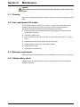
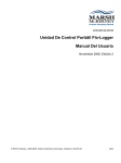
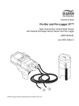
DOC026.53.00790
Flo-Station (AC/DC) Monitor
User Manual
November 2009, Edition 3
© Hach Company, 2008, 2009. All rights reserved. Printed in the U.S.A
mm/kt
Table of Contents
Section 1 Specifications .................................................................................................................... 3
Section 2 General information ......................................................................................................... 5
2.1 Safety information ........................................................................................................................ 5
2.1.1 Use of hazard information................................................................................................... 5
2.1.2 Precautionary labels ........................................................................................................... 5
2.1.3 Confined space precautions ............................................................................................... 6
2.2 Product overview ......................................................................................................................... 7
2.2.1 System features .................................................................................................................. 7
2.2.2 Applications......................................................................................................................... 8
2.3 Unpack the instrument ................................................................................................................. 8
2.4 Front panel .................................................................................................................................. 8
Section 3 Installation .......................................................................................................................... 9
3.1 Mount the instrument ................................................................................................................... 9
3.2 Electrical connections ............................................................................................................... 10
3.2.1 Electrostatic Discharge (ESD) considerations .................................................................. 10
3.2.2 Wiring for power................................................................................................................ 10
3.2.2.1 AC power ................................................................................................................. 10
3.2.2.2 DC power ................................................................................................................. 12
3.2.3 Sensor cable connections................................................................................................. 13
3.2.4 4-20 mA output connections ............................................................................................. 14
3.2.5 Additional connections ...................................................................................................... 15
3.3 Connect the power source ......................................................................................................... 15
3.4 Optional desiccant ..................................................................................................................... 16
3.5 Record the installation measurements....................................................................................... 16
Section 4 Operation .......................................................................................................................... 17
4.1 Flo-Ware .................................................................................................................................... 17
4.1.1 RS232 serial communications cable................................................................................. 17
Section 5 Maintenance .................................................................................................................... 19
5.1
5.2
5.3
5.4
Cleaning..................................................................................................................................... 19
Fuse replacement (AC model) ................................................................................................... 19
Desiccant replacement .............................................................................................................. 19
Lithium battery check ................................................................................................................. 19
Section 6 Troubleshooting ............................................................................................................. 21
Section 7 Replacement parts and accessories .......................................................................... 23
7.1 Replacement Parts .................................................................................................................... 23
Section 8 Contact Information ....................................................................................................... 25
1
Table of Contents
2
Section 1
Specifications
Specifications are subject to change without notice.
Housing
Dimensions
257.8 mm W x 236.7 mm L x 95.3 mm D (10.15 in. x 9.2 in. x 3.75 in.)
Weight
2.3 kg (5 lb)
Enclosure
ABS Plastic, NEMA 4
Operating temperature
-10 °C to 50 °C (14 °F to 122 °F), -20 °C to 50 °C (-4 °F to 122 °F) without display
Storage temperature
-40° C to 60° C (-40 °F to 140 °F) without display
-20° C to 60° C (4 °F to 140 °F) with display
Power requirements
AC
85-264 VAC, 47-63 Hz, 32 watts
DC
12 VDC for Flo-Station without display or Flo-Station with display (Backlight off)
180 mA (2.1 watts) with (1) 4-20 mA utilized
General
Data storage
64 k (16 k cycles of velocity/level data)
Local terminal
RS232C at 19.2K Baud
Optional display
Dimensions: 1 in. x 3 in. Four lines of text display, FLOW, LEVEL, VELOCITY, TOTAL or any
combination of any four channels containing data. Screens may be programmed to alternate
values displayed.
Timebase accuracy
1 second per day
Outputs
Four 4-20 mA outputs; system isolated, up to 600 ohm load. The 4-20 mA outputs are flow,
level, velocity or surcharge level.
Contact closure
Dry contact closure with adjustable duration selectable (2 seconds maximum) for
flow-proportional or alarm based on flow, level, velocity or surcharge level, temperature,
battery voltage, each sample, bad sample or analog input.
Rating: 1 A at 30 VDC (resistive); 0.5 A at 125 VAC (resistive).
Setup/Data retrieval
Flo-Ware for windows software is the user on-site setup, data management, and report
generation software. It is compatible with desktop/portable computers using
Windows 95/98/2000/Me/NT/XP. Flo-Ware for windows software can retrieve data from both
Flo-Tote and Flo-Dar flow meters. Flo-Ware FX for Pocket PC has all of the same functionality
as Flo-Ware for Windows with the exception of report generation.
Warranty
Warranty
1 year
3
Specifications
4
Section 2
General information
The contents of this manual is thought to be accurate. The manufacturer is not liable for
direct, indirect, special, incidental or consequential damages resulting from any defect or
omission in this manual, even if advised of the possibility of such damages. In the interest
of continued product development, the manufacturer reserves the right to make
improvements in this manual and the products it describes at any time, without notice or
obligation. Revised editions are found on the manufacturer’s website.
2.1 Safety information
Please read this entire manual before unpacking, setting up or operating this equipment.
Pay attention to all danger, warning and caution statements. Failure to do so could result
in serious injury to the operator or damage to the equipment.
To make sure that the protection provided by this equipment is not impaired, do not use
or install this equipment in any manner other than that specified in this manual.
2.1.1 Use of hazard information
DANGER
Indicates a potentially or imminently hazardous situation which, if not avoided, will
result in death or serious injury.
WARNING
Indicates a potentially or imminently hazardous situation which, if not avoided,
could result in death or serious injury.
CAUTION
Indicates a potentially hazardous situation that may result in minor or moderate
injury.
Important Note: Indicates a situation which, if not avoided, may cause damage to the
instrument. Information that requires special emphasis.
Notice: Indicates a situation that is not related to personal injury.
2.1.2 Precautionary labels
Read all labels and tags attached to the instrument. Personal injury or damage to the
instrument could occur if not observed.
This is the safety alert symbol. Obey all safety messages that follow this symbol to avoid potential injury. If on the
instrument, refer to the instruction manual for operation or safety information.
This symbol, when noted on the product, indicates that a risk of electrical shock and/or electrocution exists.
This symbol, when noted on the product, identifies the location of the connection for Protective Earth (ground).
This symbol, when noted on the product, identifies the location of a fuse or current limiting device.
This symbol indicates the presence of devices sensitive to Electro-static Discharge (ESD) and indicates that care
must be taken to prevent damage to the equipment.
Electrical equipment marked with this symbol may not be disposed of in European public disposal systems after
12 August of 2005. In conformity with European local and national regulations (EU Directive 2002/96/EC),
European electrical equipment users must now return old or end-of life equipment to the Producer for disposal at no
charge to the user.
Note: For return for recycling, please contact the equipment producer or supplier for instructions on how to return
end-of-life equipment, producer-supplied electrical accessories, and all auxiliary items for proper disposal.
5
General information
2.1.3 Confined space precautions
DANGER
Explosion hazard. Training in pre-entry testing, ventilation, entry procedures,
evacuation/rescue procedures and safety work practices is necessary to ensure
against the loss of life in confined spaces.
Important Note: The following information is provided to guide users of Flo-Station Flow
Meters on the dangers and risks associated with entry into confined spaces.
On April 15, 1993, OSHA’s final ruling on CFR 1910.146, Permit Required Confined
Spaces, became law. This new standard directly affects more than 250,000 industrial
sites in the U.S.A., and was created to protect the health and safety of workers in
confined spaces.
Definition of a confined space:
A confined space is any location or enclosure that presents or has the immediate
potential to present one or more of the following conditions:
•
An atmosphere with less than 19.5% or greater than 23.5% oxygen and/or more than
10 ppm Hydrogen Sulfide (H2S).
•
An atmosphere that may be flammable or explosive due to gases, vapors, mists, dusts
or fibers.
•
Toxic materials which upon contact or inhalation, could result in injury, impairment of
health or death.
Confined spaces are not designed for human occupancy. They have restricted entry and
contain known or potential hazards. Examples of confined spaces include manholes,
stacks, pipes, vats, switch vaults, and other similar locations.
Standard safety procedures must always be followed prior to entry into confined spaces
and/or locations where hazardous gases, vapors, mists, dusts or fibers may be present.
Before entering any confined space check with your employer for procedures related to
confined space entry.
6
General information
2.2 Product overview
The Flo-Station Monitor controls and transmits flow data from Marsh-McBirney (MMI)
sensors (Figure 1). The Flo-Station becomes a powerful open-channel flow meter and
data reporting system when it is used with the following components:
•
MMI sensors
•
Flo-Ware software
•
Portable computer or pocket PC (not supplied)
Figure 1 Typical Flo-Station system
1
AC or DC power cable
4
Flo-Dar sensor cable
2
RS232 interface cable
5
Surcharge Velocity Sensor (SVS) cable
3
Flo-Tote 3 sensor cable
2.2.1 System features
The flow meter consists of the Flo-Station Monitor, a sensor unit (sold separately), and
the sensor mounting frame assembly (sold separately). Refer to Figure 1. There are two
versions of mounting hardware--permanent and temporary.
Note: The Flo-Tote 3 sensor requires a mounting band for installation.
The four 4-20 mA outputs provide a convenient way to transfer real-time flow data to
SCADA and other data collection systems, control systems and display devices. The
optional display shows the flow, velocity, level, totalized flow and other channels.
7
General information
2.2.2 Applications
•
Billing purposes
•
EPA permitting requirements
•
Inflow/Infiltration studies
•
Combined sewer overflow monitoring
•
Process control
•
Modeling/Sewer system evaluations
•
Wastewater treatment plant balancing
2.3 Unpack the instrument
Remove the Flo-Station and the included RS232 interface cable from the shipping carton.
Inspect for any visible damage. If an item is missing or damaged, contact the
manufacturer (Section 8 on page 25).
2.4 Front panel
Refer to Figure 2 for the Flo-Station Monitor front panel features.
Figure 2 Flo-Station Monitor features
1
Bottom cover
5
RS232 connector
2
Cover attachment screw
6
Atmospheric pressure reference (APR) port hydrophobic
filter
3
Side channel cover access
7
Conduit hubs and strain relief fittings
4
Display (if equipped)
8
Section 3
Installation
3.1 Mount the instrument
DANGER
Potential confined space hazards. The monitor is not suitable for manhole
installations.
DANGER
Only qualified personnel should conduct the tasks described in this section of the
manual.
Important Note: Do not mount the monitor in locations that receive direct exposure to
sunlight or rain.
Install the monitor on a flat surface indoors or in an environmental enclosure or protective
covering outdoors.
1. Position the unit on the mounting surface. Make sure the unit is approximately
eye-level with the cable entry side facing downward (Figure 3).
2. Mark the mounting hole positions and drill the appropriate-sized holes at the marked
locations.
3. Use 6 screws or bolts to attach the monitor to the surface. Choose a fastener that is
suitable for the mounting surface (concrete, wood, metal, etc.).
Note: The clearance through the mounting holes is 0.2 inches.
4. Make sure the unit is secure.
Figure 3 Instrument dimensions
9
Installation
3.2 Electrical connections
DANGER
Electrocution hazard. Always disconnect power to the instrument when making
any electrical connections.
When making any wiring connections to the instrument, the following warnings and notes
must be adhered to, as well as any warnings and notes found throughout the individual
installation sections. For more safety information refer to section 2.1 on page 5.
3.2.1
Electrostatic Discharge (ESD) considerations
Important Note: To minimize hazards and ESD risks, maintenance procedures not
requiring power to the analyzer should be performed with power disconnected.
Delicate internal electronic components can be damaged by static electricity, resulting in
degraded instrument performance or eventual failure.
The manufacturer recommends taking the following steps to prevent ESD damage to
your instrument:
•
Before touching any instrument electronic components (such as printed circuit cards
and the components on them) discharge static electricity from your body. This can be
accomplished by touching an earth-grounded metal surface such as the chassis of an
instrument or a metal conduit or pipe.
•
To reduce static build-up, avoid excessive movement. Transport static-sensitive
components in anti-static containers or packaging.
•
To discharge static electricity from your body and keep it discharged, wear a wrist
strap connected by a wire to earth ground.
•
Handle all static-sensitive components in a static-safe area. If possible, use anti-static
floor and work bench pads.
3.2.2 Wiring for power
The AC and DC units have different power connectors. DC units have a fixed 2-terminal
connector and AC units have a removable connector for the neutral and line wires. Use a
screwdriver to secure all wiring connections.
3.2.2.1 AC power
Important Note: Always use 18 AWG wire, stranded with 85% overall braid.
1. Remove the bottom cover (Figure 2 on page 8).
2. Insert the power cable through the strain relief fitting or conduit hub in the bottom of
the enclosure.
3. Properly prepare each wire (Figure 4).
4. Install the ground wire to the protective earth grounding block (Figure 5). Make sure
the ground wire is securely connected.
5. Install the neutral and line wires into the AC power connector. Refer to Table 1.
Tighten each wire and then tug gently to make sure the connection is tight.
6. Plug the connector into the 100-240 VAC power block.
7. Tighten the strain relief, if used, to secure the cord.
8. Seal any unused openings in the enclosure with conduit sealing plugs.
9. Install the bottom cover.
10
Installation
Figure 4 Wiring preparation and insertion
1
Strip ¼-inch of insulation.
2
Seat insulation against connector with no bare wire exposed.
Table 1 Wiring information for AC power
Terminal description
Wire color code for North America
Wire color code for EU
Hot
Black
Brown
Neutral
White
Blue
Protective Earth (PE)
Green
Green w/yellow tracer
Figure 5 Wiring for AC power
1
Fuse holder
5
Line wire
2
Power reset button
6
AC power block
3
Ground wire
7
Protective earth grounding block
4
Neutral wire
11
Installation
3.2.2.2 DC power
WARNING
Do not connect AC power to a DC monitor.
Important Note: Always use 18 AWG wire, stranded with 85% overall braid.
1. Remove the bottom cover (Figure 2 on page 8).
2. Insert the power cable through the strain relief fitting or conduit hub in the bottom of
the enclosure.
3. Properly prepare each wire (Figure 4 on page 11).
4. Install the ground wire or cable braid to the protective earth grounding block
(Figure 6, item 2 and item 6). Make sure the ground wire is securely connected.
5. Install the negative wire first and then the positive wire into the power terminal.
Tighten each wire and then tug gently to make sure the connection is tight.
6. Tighten the strain relief, if used, to secure the cord.
7. Seal any unused openings in the enclosure with conduit sealing plugs.
8. Install the bottom cover.
Figure 6 Wiring for DC power
1
Power reset button
4
Positive wire
2
Ground wire
5
DC power terminal
3
Negative wire
6
Protective earth grounding block
12
Installation
3.2.3 Sensor cable connections
DANGER
Potential confined space hazards. If conduit is installed from the monitor to the
sensor, the conduit must be sealed to keep sewer gases out of the electronics.
The S1 terminal block is used for the Flo-Dar or Flo-Tote 3 sensor connections. The S2
terminal block is used for the optional Flo-Dar SVS sensor connections (Figure 7).
1. Disconnect power to the Flo-Station Monitor.
2. Remove the bottom cover.
3. Make sure that the ground wire is connected to the protective earth grounding block.
4. Insert the sensor cable(s) through the strain relief fitting or conduit hub near the
S1 and S2 terminal blocks.
5. Install each wire into the terminal block as shown in Figure 7 and Table 2. Tighten
each wire and then tug gently to make sure the connection is tight.
6. Insert the APR reference tube into the strain relief fitting until it stops
(Figure 7, item 2).
7. Tighten the strain relief, if used, to secure the cable(s).
8. Install the bottom cover.
Figure 7 S1 and S2 terminal blocks
1
Strain relief fitting
2
APR reference tube
3
Sensor cable
Table 2 Terminal block connections for Flo-Dar, Flo-Tote 3 and Flo-Dar optional SVS sensor
Terminal
Flo-Dar wire color (S1)
Flo-Tote 3 wire color (S1)
SVS wire color (S2)
1
White
White
White
2
Black
Black
Black
3
Clear
Orange
Orange
4
Red
Red
Red
5
Green
Green
Green
6
Black
Black
Black
13
Installation
3.2.4 4-20 mA output connections
Important Note: Always use 12 to 22 AWG, stranded, twisted pair wire.
1. Disconnect power to the Flo-Station Monitor.
2. Remove the bottom cover.
3. Make sure that the ground wire is connected to the protective earth grounding block
(Figure 5 on page 11 or Figure 6 on page 12).
4. Insert the cable(s) through the strain relief fitting or conduit hub near the CP1
terminal block (Figure 8).
5. Install each wire into the terminal block. Tighten each wire and then tug gently to
make sure the connection is tight.
Note: Each terminal is labeled (+, -) for polarity. This is the voltage polarity when a load
resistance is placed across the terminals.
6. Tighten the strain relief, if used, to secure the cable(s).
7. Install the bottom cover.
Figure 8 CP1 terminal block connections for 4-20 mA outputs
1
14
Flow (Channel 1)
2
Level (Channel 2)
3
Velocity (Channel 3)
4
Surcharge level
(Channel 4)
Installation
3.2.5 Additional connections
Important Note: Always use 12 to 22 AWG, stranded, twisted pair wire.
The following optional connections can be made on the CP2 terminal block:
•
Contact closure-single pole, rated resistive load 0.5A, 60 VDC; 0.5A, 60 VAC
normally open pole contact.
•
Output voltage-12 VDC, 150 mA output to power external devices.
•
Input voltage-0 to + 5 V input for logging only.
1. Disconnect power to the Flo-Station Monitor.
2. Remove the bottom cover.
3. Make sure that the ground wire is connected to the protective earth grounding block
(Figure 5 on page 11 or Figure 6 on page 12).
4. Insert the cable(s) through the strain relief fitting or conduit hub near the CP2
terminal block (Figure 9).
5. Install each wire into the terminal block. Tighten each wire and then tug gently to
make sure the connection is tight.
6. Tighten the strain relief, if used, to secure the cable(s).
7. Install the bottom cover.
Figure 9 CP2 terminal block connections for input and contact closure
1
Contact closure, normally open
2
Output voltage, 12 VDC
3
Input voltage, 0 to +5 V
4
Do not use
3.3 Connect the power source
DANGER
Electrocution hazard. Hazardous supply voltage can shock or cause death. Do not
connect AC power to a DC Monitor.
1. Check all connections.
2. Replace bottom panel cover.
3. Tighten screws on cover.
15
Installation
3.4 Optional desiccant
Install the Flo-Station monitor in a relatively dry environment such as a control room or
other suitable space. A hydrophobic filter is attached to the atmospheric pressure
reference (APR) port to absorb excess moisture. This filter is all that is required for most
applications.
If the monitor is installed in a high moisture environment such as a pit, install an optional
desiccant cartridge (Section 7 on page 23). The desiccant cartridge protects the APR
tube from moisture and debris that can affect the accuracy of the surcharge level
pressure transducer on a Flo-Dar sensor or primary level on a Flo-Tote 3 sensor.
1. Remove the hydrophobic filter and attach the desiccant cartridge to the APR port
(Figure 10).
Note: Two cartridges can be used in series for extra protection.
2. Replace the desiccant cartridge when the color changes to pink.
Figure 10 Desiccant cartridges
1
Hydrophobic filter
2
Moist environment desiccant
cartridge
3
Low maintenance, moist
environment desiccant cartridge
3.5 Record the installation measurements
1. Document the site specific data (location, site ID and description).
2. Enter the installation date.
3. Record the serial numbers of the monitor and sensor.
4. Record pipe inside dimension (ID) number.
5. Record Level offset, Sensor Offset or Level Cal as appropriate. Refer to the sensor
manual for the installed sensor.
6. Record the sediment level if applicable.
16
Section 4
Operation
4.1 Flo-Ware
Note: The Flo-WareTM T200 Software with Flo-Dar or Flo-Tote 3 file driver is required to set up the
Flo-Station.
The Flo-Ware for Windows software model T200 is a data management and instrument
communication software package. The software package includes an instrument driver,
chart reports, text reports, data editing, text report designer and language designer, site
set-up data collection, real time calibration, computer interface cable and an instruction
manual. The Flo-Ware is provided on a CD and the Flo-Ware FX is provided on an
SD card.
Detailed instructions for using Flo-Ware T200 software are contained in the Flo-Ware
User Manual. The 4-20 mA output setup instructions are found in the extended setup
section. Instructions are also accessed directly from the T200 program via the Help
function. The sensor offset and site specific information such as pipe shape, pipe ID and
sediment level obtained during sensor installation will need to be entered into the site
setup section of T-200 Flo-Dar communications. For Flo-Dar sensors the “Flow Cal
Method” is typically set for “Direct Mean Velocity” for circular pipes. If the application is a
rectangular channel, the “Flow Cal Method” is set for “Velocity Multiplier”.
When using the Flo-Dar sensor, select “Extended Setup” if you have the optional
extended range feature. Select “Extended Range” level transducer on the ultrasonic level
call screen. Flo-Tote 3 sensors use a "Site Calibration Coefficient". Refer to the Flo-Tote 3
user manual for profiling and setting the site calibration coefficient.
4.1.1 RS232 serial communications cable
A portable computer with Flo-Ware software must be connected via a communication
cable to the Flo-Station to set up and collect data from the flow meter. The
communication cable is included as part of the Flo-Ware software package. Extra cables
may be purchased by registered Flo-Ware users.
The RS232 Serial Communications Connector is located on the front panel of the
Flo-Station housing. The front panel should remain in place whenever the communication
cable is not connected.
1. Pull the side channel away from the side of the top cover (Figure 11).
2. Remove the piece of molding from the channel.
3. Push the channel down to release the bottom attachment and open the cover.
4. Plug the RS232 cable into the connector on the front of the monitor
17
Operation
.
Figure 11 RS232 front panel access
18
Section 5
Maintenance
DANGER
Only qualified personnel should conduct the tasks described in this section of the
manual.
5.1 Cleaning
Clean the Flo-Station periodically. Use a damp cloth only. Do not submerge or douse with
water.
5.2 Fuse replacement (AC model)
The Flo-Station Monitor contains one 5 x 20 mm, 1 A 250 V fuse. Failed fuses are an
indication that an equipment problem could exist. Problem resolution and fuse
replacement should be performed only by qualified service personnel.
1. Disconnect power to the Flo-Station Monitor (including power to relays and other
components, if powered).
2. Remove the bottom cover.
3. Use a screwdriver to open the fuse holder and remove the fuse (Figure 5 on page 11,
Item 1).
4. Replace the fuse with a fuse of the same type and rating.
5. Push and twist the cover of the fuse holder to tighten.
6. Install the bottom cover.
7. Apply power to the instrument.
5.3 Desiccant replacement
Replace the desiccant cartridge when the color changes to pink (section 3.4 on page 16).
5.4 Lithium battery check
Check the back-up lithium battery life every six months. Use the Flo-Ware software to
check the battery life.
19
Maintenance
20
Section 6
Troubleshooting
When a problem occurs, try to determine whether the problem is from the monitor, the
cables or the sensor.
Check all connections.
Check the connections and make sure that power is applied to the Flo-Station.
Verify the sensor operation.
•
Determine if the problem is with just one measurement channel or if the sensor is not
responding at all.
•
Check the sensor for debris that may have collected.
•
If the sensor is not responding, remove and inspect the connector on the sensor for
moisture. Clean and dry if necessary. Tighten this connector firmly.
Verify the monitor operation.
Write down all error codes that occur and contact the factory.
Restart the microprocessor
If the Flo-Station locks up due to a power fluctuation or unknown reason, push the red
reset button to restart the microprocessor (Figure 5 on page 11 or Figure 6 on page 12).
21
Troubleshooting
22
Section 7
Replacement parts and accessories
7.1 Replacement Parts
Description
Moisture block cartridge, air tube
Desiccant cartridge, moist environment
Desiccant cartridge, moist environment, low maintenance
RS232 interface cable
Item number
151000201
55032
5027
570007301
Fuse, AC
015804
Cord, power, AC
24500M
Software CD, Flo-Ware
800015301
23
Replacement parts and accessories
24
Section 8
Contact Information
Ordering information for the U.S.A.
By Telephone:
(800) 368-2723
By Fax:
301-874-8459
By Mail:
Hach Company
4539 Metropolitan Court
Frederick, MD 21704-9452, U.S.A
Ordering information by e-mail:
[email protected]
Information Required
•
Hach account number (if available)
•
Billing address
•
Your name and phone number
•
Shipping address
•
Purchase order number
•
Catalog number
•
Brief description or model number
•
Quantity
European Union
Flow-Tronic
Rue J.H. Cool 19a
B-4840 Welkenraedt
Belgium
Tel: + -32-87-899799
Email: [email protected]
www.flow-tronic.com
Outside the U.S.A. and EU
Hach Company maintains a worldwide network of dealers and distributors. To locate the
representative nearest you, send E-mail to [email protected] or visit
www.hachflow.co.
Technical Support
Technical and Customer Service Department personnel are eager to answer questions
about our products and their use. In the U.S.A., call 1-800-635-1230. Outside the U.S.A.
and Europe, send E-mail to [email protected] or call 1-301-874-5599.
Repair Service
Authorization must be obtained from Hach Company before sending any items for repair.
To send the monitor to the factory for repair:
1. Identify the serial number of the monitor unit.
2. Record the reason for return.
3. Call the Customer Service Department (1-800-368-2723) and get a Service Request
Number (SRN) and shipping label.
4. Use the shipping label provided and ship the equipment in the original packaging if
possible.
Note: Do not ship manuals, computer cables, or other parts with the unit unless they are required for
repair.
25
Contact Information
5. Make sure the equipment is free from foreign debris and is clean and dry before
shipping. Sensors returned without cleaning will be charged a fee.
6. Write the SRN number on the shipping box.
7. Make sure that all return shipments are insured.
8. Address all shipments to:
Hach Company
5600 Lindbergh Drive - North Dock
Loveland, Colorado, 80539-0389 U.S.A.
Attn: SRN#XXX
26