1
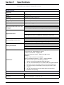
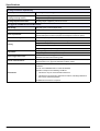
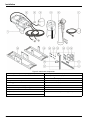
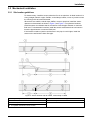
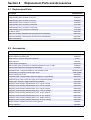
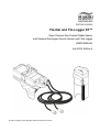
DOC026.53.80035
Flo-Dar and Flo-Logger XT™
Open Channel Non-Contact Radar Sensor
with Optional Surcharge Velocity Sensor and Flow Logger
USER MANUAL
July 2009, Edition 2
© HACH Company, 2009. All rights reserved. Printed in the U.S.A.
Table of Contents
Section 1 Specifications ....................................................................................................................... 5
Section 2 General information.............................................................................................................. 7
2.1 Safety information ........................................................................................................................ 7
2.1.1 Use of hazard information................................................................................................... 7
2.1.2 Precautionary labels ........................................................................................................... 7
2.1.3 Confined space precautions ............................................................................................... 8
2.1.4 FCC Regulations................................................................................................................. 8
2.2 Product overview ......................................................................................................................... 9
2.2.1 Theory of operation............................................................................................................. 9
Section 3 Installation ........................................................................................................................... 11
3.1 Component list ........................................................................................................................... 11
3.2 Mechanical installation............................................................................................................... 13
3.2.1 Site location guidelines ..................................................................................................... 13
3.2.2 Sensor installation............................................................................................................. 15
3.2.2.1 Assemble the clamps on the frame and wall bracket............................................... 17
3.2.2.2 Install the frame on the wall ..................................................................................... 19
3.2.2.3 Install the sensor on the frame................................................................................. 20
3.2.2.4 Align the sensor vertically—Flo-Dar XT without SVS............................................... 21
3.2.2.5 Align the sensor vertically—Flo-Dar XT with SVS.................................................... 22
3.2.2.6 Align the sensor horizontally .................................................................................... 23
3.2.2.7 Make a final alignment check................................................................................... 23
3.2.2.8 Optional extended depth sensor installation ............................................................ 24
3.2.3 Measure the sensor offset ................................................................................................ 26
3.2.4 Measure the pipe diameter ............................................................................................... 27
3.3 Electrical installation .................................................................................................................. 27
3.3.1 Wiring safety information .................................................................................................. 27
3.3.1.1 Electrostatic Discharge (ESD) considerations ......................................................... 27
3.3.2 Mechanical installation...................................................................................................... 28
3.4 Installing the Flo-Logger XT....................................................................................................... 29
3.4.1 Desiccant cartridge ........................................................................................................... 29
3.4.2 Attach the Flo-Logger XT.................................................................................................. 30
3.4.3 Sensor connection ............................................................................................................ 30
3.5 Battery installation...................................................................................................................... 30
3.5.1 Internal lithium battery installation..................................................................................... 31
3.5.2 External alkaline battery installation.................................................................................. 32
3.5.2.1 Battery life ................................................................................................................ 32
3.5.2.2 Data back-up coin cell.............................................................................................. 32
Section 4 Programming the XT .......................................................................................................... 33
4.1 Setup.......................................................................................................................................... 33
4.2 Programming the recorder ......................................................................................................... 39
4.3 Check Real Time readings......................................................................................................... 39
4.4 Checking server communications .............................................................................................. 41
Section 5 Maintenance ........................................................................................................................ 43
5.1 Preventive maintenance ............................................................................................................ 43
5.2 Cleaning the instrument ............................................................................................................. 44
5.3 Cable replacement..................................................................................................................... 44
5.4 Flo-Logger XT maintenance ...................................................................................................... 45
5.4.1 Flo-Logger XT cleaning..................................................................................................... 45
5.4.2 Desiccant replacement ..................................................................................................... 45
Section 6 Troubleshooting.................................................................................................................. 47
3
Table of Contents
Section 7 Limited warranty..................................................................................................................49
Section 8 Replacement Parts and Accessories ................................................................................51
8.1 Replacement Parts.....................................................................................................................51
8.2 Accessories ................................................................................................................................51
Section 9 Contact Information ............................................................................................................53
Section 1
Specifications
Specifications are subject to change without notice.
Flo-Dar XT sensor
Dimensions
160.5 W x 432.2 L x 297 D mm (6.32 x 16.66 x 11.7 in.) With SVS, D = 387 mm
(15.2 in.)
Weight
4.8 kg (10.5 lb)
Enclosure
IP68 waterproof rating, polystyrene
Operating temperature
–10 to 50 °C (14 to 122 °F)
Storage temperature
–40 to 60 °C (–40 to 140 °F)
Power requirements
Supplied by Flo-Logger XT
Interconnecting cable (can be
disconnected at both the sensor and
the logger)
Polyurethane, 0.400 (±0.015) in. diameter
IP68
Standard length 9 m (30 ft), maximum length 305 m (1000 ft)
Method: Ultrasonic
Depth measurement
Standard operating range from Flo-Dar housing to liquid: 0 to 152.4 cm (0 to 60
in.)
Optional extended operating range from transducer face to liquid: 0 to 6.1 m (0
to 20 ft) (with 43.18 cm (17 in.) deadband), temperature compensated
Accuracy: ±1% ±0.25 cm (±0.1 in.)
Method: Piezo-resistive pressure transducer with stainless steel diaphragm
Surcharge depth measurement
Auto zero function maintains zero error < 0.5 cm (0.2 in.)
Range: 3.5 m (138 in.), overpressure rating 2.5 x full scale
Method: Radar 24.125 GHz
Velocity measurement
Range: 0.23 m/s to 6.10 m/s (0.75 to 20 ft/s)
Frequency Range: 24.075 to 24.175 GHz, 15.2mW (max.)
Accuracy: ±0.5%; ±0.03 m/s (±0.1 ft/s)
Certifications
The Flodar Transmitter is Certified to the following requirements:
– Transmitter type : Field Disturbance Sensor
– Frequency: 24.125 Ghz - Doppler pulse
– Maximum rated power output: 128dbuV(ave) @ 3 meters
Certified to:
FCC Part 15.245: FCC ID: VIC-FLODAR24
Industry Canada Spec. RSS210. v7: IC No.: 6149A-FLODAR24
Use of this device is subject to the following conditions:
1 There are no used serviceable items inside this device.
2
The user must install this device in accordance with the supplied installation
instructions and must not modify the device in any manor whatsoever.
3
Any service involving the transmitter must only be performed by Hach
Company.
4
The user must ensure that no one is within 20cm of the face of the
transmitter when operating.
Flow measurement
Method
Based on continuity equation
Accuracy
± 5% of reading typical where flow is in a channel with uniform flow conditions
and is not surcharged, ± 1% full scale max.
5
Specifications
Surcharge Conditions Depth/Velocity
Power requirements
Power supplied by Flo-Logger XT
Velocity measurement (optional
surcharge velocity sensor)
Method: Electromagnetic
Surcharge depth measurement
Surcharge depth supplied by Flo-Dar XT sensor.
Range: ± 6.1 m/s (± 20 ft/s)
Flo-Logger XT Portable DC Powered Electronics
Data storage
64K (16K cycles of velocity/depth data)
Local terminal
RS232C at 19.2K baud
Power requirements
Lithium battery pack housed in the logger or alkaline battery pack housed in a
separate waterproof enclosure (requires external power connector option)
Timebase accuracy
One second per day
Sealed watertight polystyrene - meets IP68 rating
Housing
Length: 37.03 cm (14.625 in.)
Diameter: 19.69 cm (7.75 in.)
Weight: 4.4 kg (9.8 lbs.) including lithium batteries
Temperature
Operating range: -10 to 51 °C (14 to 125 °F)
Storage range: -20 to 51 °C (-4 to 125 °F)
Sensor/Logger disconnect
Both the sensor and the logger have waterproof (IP68) connectors for easy
separation from the interconnecting cable.
Remote communications
RTU configured with a packet switched IP protocol data over a cellular network,
supported with a FCC approved embedded cellular modem.
Certifications
This Intentional Transmitter is FCC and Industry Canada listed.
Certified to:
FCC ID: VIC-FLODAR24 and IC: 6149A-FLODAR24.
Operation is subject to the following conditions:
1 This device may not cause harmful interference.
2
This device must accept any interference received, including interference
that causes undesired operation.
No additional user license is required.
6
Section 2
General information
2.1 Safety information
Please read this entire manual before unpacking, setting up, or operating this equipment.
Pay attention to all danger and caution statements. Failure to do so could result in serious
injury to the operator or damage to the equipment.
To ensure that the protection provided by this equipment is not impaired, do not use or
install this equipment in any manner other than that specified in this manual.
2.1.1 Use of hazard information
DANGER
Indicates a potentially or imminently hazardous situation which, if not avoided, will
result in death or serious injury.
WARNING
Indicates a potentially or imminently hazardous situation which, if not avoided,
could result in death or serious injury.
CAUTION
Indicates a potentially hazardous situation that may result in minor or moderate
injury.
Important Note: Indicates a situation which, if not avoided, may cause damage to the
instrument. Information that requires special emphasis.
Note: Information that supplements points in the main text.
2.1.2 Precautionary labels
Read all labels and tags attached to the instrument. Personal injury or damage to the
instrument could occur if not observed.
This is the safety alert symbol. Obey all safety messages that follow this symbol to avoid potential injury. If on the
instrument, refer to the instruction manual for operation or safety information.
Electrical equipment marked with this symbol may not be disposed of in European public disposal systems after
12 August of 2005. In conformity with European local and national regulations (EU Directive 2002/96/EC),
European electrical equipment users must now return old or end-of life equipment to the Producer for disposal at no
charge to the user.
Note: For return for recycling, please contact the equipment producer or supplier for instructions on how to return
end-of-life equipment, producer-supplied electrical accessories, and all auxiliary items for proper disposal.
This symbol, when noted on a product enclosure or barrier, indicates that a risk of electrical shock and/or
electrocution exists.
This symbol, when noted on the product, identifies the location of the connection for Protective Earth (ground).
This symbol, when noted on the product, identifies the location of a fuse or current limiting device.
This symbol, when noted on the product, indicated the presence of devices sensitive to Electro-static Discharge
(ESD) and indicated that care must be taken to prevent damage with the equipment.
7
General information
2.1.3 Confined space precautions
DANGER
Explosion hazard. Training in pre-entry testing, ventilation, entry procedures,
evacuation/rescue procedures and safety work practices is necessary before
entering confined spaces.
Important Note: The following information is provided to guide users of Flo-Dar XT and
SVS Sensors on the dangers and risks associated with entry into confined spaces.
On April 15, 1993, OSHA’s final ruling on CFR 1910.146, Permit Required Confined
Spaces, became law. This new standard directly affects more than 250,000 industrial
sites in the U.S.A., and was created to protect the health and safety of workers in
confined spaces.
Definition of a confined space:
A confined space is any location or enclosure that presents or has the immediate
potential to present one or more of the following conditions:
•
An atmosphere with less than 19.5% or greater than 23.5% oxygen and/or more than
10 ppm Hydrogen Sulfide (H2S).
•
An atmosphere that may be flammable or explosive due to gases, vapors, mists, dusts
or fibers.
•
Toxic materials which upon contact or inhalation, could result in injury, impairment of
health or death.
Confined spaces are not designed for human occupancy. They have restricted entry and
contain known or potential hazards. Examples of confined spaces include manholes,
stacks, pipes, vats, switch vaults, and other similar locations.
Standard safety procedures must always be followed prior to entry into confined spaces
and/or locations where hazardous gases, vapors, mists, dusts or fibers may be present.
Before entering any confined space check with your employer for procedures related to
confined space entry.
2.1.4 FCC Regulations
This Intentional Transmitter is FCC and Industry Canada listed. FCC ID: VIC-FLODAR24
and IC: 6149A-FLODAR24.
Operation is subject to the following two conditions:
1. This device may not cause harmful interference.
2. This device must accept any interference received, including interference that causes
undesired operation.
No additional user license is required. Any changes or modifications not expressly
approved by Hach Company, Inc. could void the users authority to operate the
equipment.
8
General information
2.2 Product overview
The Flo-Dar XT Sensor measures the flow velocity and liquid depth in open channels
using radar and ultrasonic technology. The unit is designed to withstand submersion
during surcharge conditions. The optional surcharge velocity sensor provides velocity
measurements during surcharge conditions.
Figure 1 shows the configuration of an XT system in a suitable location.
Figure 1 System overview
1
Flo-Dar sensor with optional surcharge velocity sensor
4
Flo-Logger XT
2
External long-life alkaline battery (optional)
5
Mounting frame
3
Burial antenna
6
Suitable environment
2.2.1 Theory of operation
The Flo-Dar XT Sensor is mounted above an open channel of water and measures the
surface velocity and depth from above the surface of the water. The two measurements
are used to calculate the flow rate.
During surcharge (submerged) conditions, a pressure transducer measures depth. The
optional surcharge velocity sensor (SVS) can be used to measure velocity during
surcharge conditions.
Surface velocity measurement
The surface velocity of the water is measured using radar technology. A radar beam is
transmitted from the sensor to the water surface at the center of the channel. A portion of
the signal is reflected back at a slightly different frequency. The difference in frequency,
known as the Doppler frequency, is directly proportional to the speed of the flow.
Proprietary algorithms are then used to calculate the average speed of the flow stream.
Note: The radar velocity sensor does not operate under surcharge conditions.
9
General information
Velocity measurements during surcharge
The optional surcharge velocity sensor (SVS) is activated when the flow level rises to
within seven inches of the sensor mounting frame and remains active until the flow falls
to seven inches below the sensor mounting frame. The mounting frame is installed five to
six inches above the crown of the pipe. This places the velocity sensing electrodes at the
correct location in the flow below the elevation of the crown of the pipe.
The SVS measures velocity using an electromagnetic sensor that generates a magnetic
field. When the water passes through the magnetic field, a voltage is generated that is
directly proportional to the speed of the water passing the sensor.
Depth measurement
The water depth is measured using an ultrasonic pulse echo sensor. An electronic pulse
is sent to the water surface and a portion of the signal is returned to the sensor. The
transit time to the surface and back is used to calculate the distance from the water
surface to the sensor. The pipe diameter is used to convert the distance to water depth.
The depth sensor on the Flo-Dar XT unit can measure distances up to 1.5 m (5 ft). For
larger channels, an extended range sensor is available to measure up to 6.1 m (20 ft).
During surcharge conditions, a pressure transducer in the Flo-Dar XT unit is used to
measure depth.
Flow calculations
The velocity and depth measurements are used with the pipe diameter to determine the
flow rate. The flow rate is calculated from the continuity equation (1):
(1) Flow rate = Average velocity × Area
where
Flow rate = volume of liquid that passes the sensor per unit time (e.g. 200 gallons per minute)
Average velocity = average velocity of the liquid, calculated using surface velocity
measurements and algorithms
Area = cross-sectional area of the liquid in the channel, calculated using the channel
dimensions and depth measurement.
10
Section 3
Installation
DANGER: Potential Explosion Hazard
CAUTION: Radar RF Exposure Hazard
Although the Flo-Dar XT microwave power level is very small (~15mW) and is well
below government stated exposure limits for uncontrolled environments, users of
this product should follow proper safety protocols for the handling of devices with
radar frequency transmitters. Avoid placing the head and other vital organ areas
within the microwave beam (within 1 meter of the microwave aperture).
3.1 Component list
Important Note: Delicate Instrumentation. Handle with care to prevent damage to the
microwave transmitter. Damaged transmitters can result in higher signal power levels,
which can interfere with essential terrestrial microwave links.
Make sure that the instrument components shown in Figure 2 have been received.
11
Installation
Figure 2 Instrument components
1
Surcharge velocity sensor (SVS) (optional)
11 Clamp half, not threaded (2x)
2
Flo-Dar sensor
12 Clamp bolt, ¼-20 x 1 in. (8x)
3
Bubble level
13 Anchor nut, 3/8-16 (2x)
4
Optional extended depth sensor
14 Anchor washer (2x)
5
Flo-logger XT
15 Anchor, 3/8 x 2¼ in. (2x)
6
External alkaline battery (optional)
16 Adjustable wall bracket
7
Antenna, burial (ordered separately)
17 Wall mount bracket
8
Spacer, 12-inch
18 Standard frame
9
Spacer, 2¼ inch
19 Frame for extended depth sensor (optional)
10
12
Installation
3.2 Mechanical installation
3.2.1 Site location guidelines
For best accuracy, install the sensor where the flow is not turbulent. An ideal location is in
a long, straight channel or pipe. Outfalls, vertical drops, baffles, curves or junctions cause
the velocity profile to become distorted.
Where there are outfalls, vertical drops, baffles, curves or junctions, install the sensor
upstream or downstream as shown in Figure 3 and Figure 4. For upstream locations,
install the sensor at a distance that is at least five times the pipe diameter or maximum
fluid level. For downstream locations, install the sensor at a distance that is at least ten
times the pipe diameter or maximum fluid level.
If the location contains a junction and the flow in one pipe is much higher, install the
sensor on the wall near the lower flow pipe.
Figure 3 Sensor location near an outfall, vertical drop or baffle
1
Acceptable upstream sensor location
5
Distance downstream: 10 x pipe diameter
2
Outfall
6
Vertical drop
3
Distance upstream: 5 x maximum level
7
Baffle
4
Acceptable downstream sensor location
13
Installation
Figure 4 Sensor location near a curve, elbow or junction
1
Acceptable upstream sensor location
3
Distance downstream: 10 x pipe diameter
2
Acceptable downstream sensor location
4
Distance upstream: 5 x pipe diameter
14
Installation
3.2.2 Sensor installation
Mount the Flo-Dar XT sensor above the open channel on the wall of the manhole. A pole
is available for retrieval of the Flo-Dar XT sensor without entry into the manhole.
For temporary installation, an optional Jack-bar is available. Refer to Replacement Parts
and Accessories on page 51. Instructions are included with the Jack-bar.
The Flo-Dar XT sensor dimensions are shown in Figure 5 and Figure 6.
Figure 5 Flo-Dar XT sensor dimensions
1
Optional extended depth sensor
2
Minimum clearance for cable with extended depth sensor
3
Minimum clearance for cable
15
Installation
Figure 6 Flo-Dar XT sensor with SVS dimensions
1
16
Minimum clearance for cable
Installation
The dimensions of the standard frame for wall installation are shown in Figure 7.
Figure 7 Standard frame dimensions
1
22.8 in. with 2¼ in. spacer; 32.6 in. with 12 in. spacer
3.2.2.1 Assemble the clamps on the frame and wall bracket
Install the clamps on the frame and wall mount bracket before installation on the wall.
Prerequisites
•
Frame
•
Wall mount bracket
•
Clamps
•
Hardware—wall bracket, spacer, nuts and bolts
Procedure
1. Position two clamp halves (one with threads and one without threads) around the wall
mount bracket as shown in Figure 8.
2. Connect the clamp halves together with four bolts. Lightly tighten the bolts to
temporarily hold the clamp in position.
17
Installation
3. Position the other two clamp halves around the front end of the frame as shown in
Figure 8.
Note: In most cases the front of the frame will point toward the wall as shown in Figure 8 (see
also Figure 12 on page 23). If flow conditions require the sensor to point away from the wall,
use the 12 inch spacer and position the two clamp halves around the back end of the frame.
4. Connect the clamp halves together with four bolts. Lightly tighten the bolts to
temporarily hold the clamp in position.
Figure 8 Clamps assembled on wall bracket and frame
1
Adjustable wall bracket
5
Frame
2
Clamp half, threaded
6
Spacer
3
Clamp bolt, ¼–20 x 1 in.
7
Wall mount bracket
4
Clamp half, not threaded
18
Installation
3.2.2.2 Install the frame on the wall
DANGER
Explosion hazard. Review the safety information in section 2.1 on page 7 before
entering a confined space.
Sensor location guidelines
Review the following guidelines to find the best location for the sensor.
•
Examine the upstream and downstream flow characteristics. Use a mirror if
necessary. Install the sensor above the water where the flow is steady. Do not install
the sensor where there are standing waves, pools or objects or materials that can
disrupt the flow profile.
•
If the upstream flow characteristics are acceptable, install the sensor on the upstream
wall of the manhole with the sensor pointing upstream. This location will make sure
that the measured flow is the same as the flow in the pipe and that the sensor cable
points away from the wall.
•
Install the sensor away from the sides of the pipe and in the very center of the flow
where the fluid is at the maximum depth.
•
Install the sensor in a location that is accessible for maintenance.
Prerequisites
•
Frame and wall mount bracket assembly (assembled in section 3.2.2.1)
•
Anchors with nuts and washers
•
Drill
•
3/8-inch
•
Tools: mirror, ruler or tape measure, marker
concrete drill bit with tape to indicate a depth of 1½ inches
Procedure
Complete the steps to install the frame on the wall of the manhole above the flow.
1. Make a mark on the wall that identifies the location of the top of the sensor frame
(Figure 9). The wall brackets will be installed above and below this mark.
•
Flo-Dar XT without SVS—make sure that when the sensor is in the frame, the
radar beam will not be blocked by the wall or channel (Figure 11).
•
Flo-Dar XT with SVS—the top of the sensor frame must be installed at an exact
distance above the top of the channel. For pipe diameters greater than 24 inches,
measure 5 inches from the top of the channel to the top of the frame. For pipe
diameters less than 24 inches, measure 6 inches from the top of the channel to
the top of the frame. Refer to Figure 9.
2. Position the wall mount brackets above and below this mark.
3. Make two marks to identify the position of the holes for each bracket.
Note: If there is not enough usable space to drill and install a mounting anchor and bracket below
the mark the wall mount bracket can be inverted with the adjustable bracket on the bottom and
above the mark. Leave enough knurled rod protruding through the adjustable bracket so the
mounting frame may be positioned at the mark. If required the wall mount bracket can be installed
horizontally at the same elevation as the mark. Custom fabrications may also be used to place the
sensor in the correct position.
4. Use a 3/8-inch drill bit to drill two holes at a depth of 1½ inches. Remove the debris
from the holes.
5. Put the anchors in the holes and tap lightly with a hammer to seat the anchors.
19
Installation
6. Position the brackets over the holes and install the washers and nuts. Hold the
brackets and tighten the nuts on the anchors. Do not over-torque.
7. Connect the frame to the wall bracket with a spacer as shown in Figure 9. The
12-inch spacer may be necessary to position the sensor farther from the wall when
there is a large pipe lip.
Figure 9 Wall installation
1
Distance from crown of pipe to top of frame
3
Washer
2
Anchor
4
Nut
3.2.2.3 Install the sensor on the frame
The sensor fits in the frame in only one direction and locks in position when the bail on
the sensor is turned (Figure 10). The sensor can be removed from the frame and installed
without entering the manhole when the optional retrieval pole is used (see Accessories
on page 51).
Procedure
1. Make sure that the cable is tightly connected to the sensor.
2. Turn the bail to retract the locking bars on the sensor.
3. Position the sensor on the frame. The cable should point toward the center of
the manhole.
4. Turn the bail to lock the sensor on the frame (Figure 10).
20
Installation
Figure 10 Horizontal alignment
1
Bubble level
2
Bail
3.2.2.4 Align the sensor vertically—Flo-Dar XT without SVS
The sensor must be aligned vertically to make sure that the sensor is above the flow and
that the radar beam will not be blocked by the wall or pipe (Figure 11).
Procedure
1. Make an estimate of where a line that extends from the top of the radar lens
perpendicular to where the lens will point (Figure 11). Use the optional laser
alignment tool for best results. (Refer to Accessories on page 51.)
2. Loosen the clamp on the wall mount bracket and position the frame so that the radar
beam will point below the crown of the pipe by at least 1 inch (Figure 11). It may be
necessary to install the 12 inch spacer to extend the frame farther from the wall. Cut
down the 12 inch spacer to the required length.
3. Tighten the clamp and measure the frame position. Make sure that the radar beam is
not blocked by the wall or pipe. If the beam is blocked, move the frame further away
from the wall using the 12 inch spacer or lower the frame.
21
Installation
Figure 11 Vertical alignment of Flo-Dar XT sensor
1
Spacer
2
Distance from crown of pipe to top of frame
3.2.2.5 Align the sensor vertically—Flo-Dar XT with SVS
The sensor must be aligned vertically to make sure that the sensor is above the flow
under normal full flow conditions and that the SVS is activated under surcharge
conditions.
Prerequisites
•
Ruler or tape measure
Procedure
1. Measure directly above the crown of the pipe to the top of the frame (Figure 9 on
page 20).
2. If the pipe lip is longer than 5½ inches, install the 12 inch spacer between the wall
mount bracket and the frame (Figure 12). Cut down the 12 inch spacer to the
required length.
3. Loosen the clamp on the wall mount bracket and position the top of the frame above
the crown of the pipe at the specified distance:
22
•
6 inches for a pipe diameter that is less than 24 inches
•
5 inches for a pipe diameter that is equal to or larger than 24 inches
Installation
4. Tighten the clamp and measure the frame position again to make sure it is at the
correct position.
Figure 12 Vertical alignment of Flo-Dar XT sensor with SVS
1
Spacer
2
Distance from crown of pipe to top of frame
3
SVS sensor (optional)
3.2.2.6 Align the sensor horizontally
The sensor must be aligned horizontally to make sure that the sensor is centered over
the flow. If the pipe is not level and has a slope of 2 degrees or more, align the sensor to
be parallel with the surface of the water.
Prerequisites
•
Bubble level
Procedure
1. Remove the paper backing from the bubble level and attach the level to the sensor
(Figure 10 on page 21).
2. Loosen the clamps and tap the frame into position.
3. Tighten both clamps and measure the frame position to make sure it is at the correct
position.
3.2.2.7 Make a final alignment check
The correct vertical and horizontal alignment of the sensor is necessary for accurate
measurements.
1. Measure the vertical alignment (section 3.2.2.4 on page 21 or section 3.2.2.5 on
page 22) and make adjustments if necessary.
23
Installation
2. Measure the horizontal alignment (section 3.2.2.6 on page 23) and make
adjustments if necessary.
3. Repeat steps 1 and 2 until no further adjustments are necessary.
3.2.2.8 Optional extended depth sensor installation
The extended depth sensor (Figure 13) can be used when the pipe or channel depth
exceeds the standard level specifications (refer to Specifications on page 5). Use the
extended frame (Figure 14) in place of the standard frame, or mount the extended depth
sensor on the wall when using the remote extended depth sensor. Unlike the standard
frame, the extended frame is reversible with regard to mounting direction.
The extended depth sensor has a deadband zone below the sensor of 16 inches where
the sensor is not active. Install the extended depth sensor at least 16 inches above the
highest expected level up to the crown of the pipe. Flo-Dar XT sensors with the SVS
option require the remote extended depth option.
Figure 13 Extended sensor dimensions
24
Installation
Figure 14 Extended frame dimensions
1
29.1 in. with 2¼ in. spacer; 38.8 in. with 12 in. spacer
Figure 15 Vertical alignment with extended depth sensor
1
Spacer
25
Installation
3.2.3 Measure the sensor offset
The sensor offset is the distance from the top of the frame to the bottom of the pipe or
channel. This distance will be entered into the software and is necessary for accurate
flow calculations.
If the extended depth sensor (section 3.2.2.8 on page 24) is installed on the wall without
the extended frame, the sensor offset is the distance from the face of the extended depth
sensor to the bottom of the pipe or channel.
Prerequisites
•
Rod
•
Tape measure
Procedure
1. Put the rod in the bottom of the pipe or channel and align it vertically with the frame
(Figure 16).
2. Make a mark on the rod to identify where the top of the sensor frame is.
3. Measure the distance from the bottom of the rod to the mark. This is the sensor
offset.
Note: If it is not practical to measure to the bottom of the pipe, measure the distance from the
crown of the pipe to the top of the frame (Figure 16). Add this distance to the pipe diameter to
get the sensor offset (sensor offset = pipe diameter + distance from crown of the pipe to top
of frame).
Figure 16 Sensor offset
1
Distance from crown of pipe to top of frame
2
Pipe diameter
26
3
Sensor offset
Installation
3.2.4 Measure the pipe diameter
The correct diameter of the pipe or channel is necessary for accurate flow calculations.
1. Measure the inside pipe diameter (I.D.) at three locations (Figure 17). Be sure that
the measurements are accurate.
2. Calculate the average of the three measurements. Record this number for use during
the software setup for the site.
Figure 17 Pipe diameter measurement
3.3 Electrical installation
3.3.1 Wiring safety information
When making any wiring connections to the instrument, the following warnings and notes
must be adhered to, as well as any warnings and notes found throughout the individual
installation sections. For more safety information refer to Safety information on page 7.
CAUTION
Possible danger to sensor or logger. Always disconnect power to the instrument
when making any electrical connections.
CAUTION: Radar RF Exposure Hazard
Although the Flo-Dar XT microwave power level is very small (~15mW) and is well
below government stated exposure limits for uncontrolled environments, users of
this product should follow proper safety protocols for the handling of devices with
radar frequency transmitters. Avoid placing the head and other vital organ areas
within the microwave beam (within 1 meter of the microwave aperture).
3.3.1.1
Electrostatic Discharge (ESD) considerations
Important Note: To minimize hazards and ESD risks, maintenance procedures not
requiring power to the instrument should be performed with power removed.
Delicate internal electronic components can be damaged by static electricity, resulting in
degraded instrument performance or eventual failure.
27
Installation
The manufacturer recommends taking the following steps to prevent ESD damage to the
instrument:
•
Before touching any instrument electronic components (such as printed circuit cards
and the components on them) discharge static electricity from your body. This can be
accomplished by touching an earth-grounded metal surface such as the chassis of an
instrument, or a metal conduit or pipe.
•
To reduce static build-up, avoid excessive movement. Transport static-sensitive
components in anti-static containers or packaging.
•
To discharge static electricity from your body and keep it discharged, wear a wrist
strap connected by a wire to earth ground.
•
Handle all static-sensitive components in a static-safe area. If possible, use anti-static
floor pads and work bench pads.
3.3.2 Mechanical installation
The Flo-Logger XT controls and transmits flow data from the Flo-Dar XT sensor.
Combined with a portable computer, telelog software, and sensors, the Flo-Logger XT
becomes a powerful open channel flowmeter and data reporting system.
28
Installation
3.4 Installing the Flo-Logger XT
Figure 18 Flo-Logger XT dimensions
3.4.1 Desiccant cartridge
Make sure that a new desiccant cartridge is attached to the atmospheric pressure
reference (APR) port found on the bottom of the Flo-Logger XT housing (Figure 19, item
6). The desiccant cartridge prevents the buildup of moisture. Moisture and other
unwanted material can change the precision of the surcharge level pressure transducer.
When a desiccant cartridge becomes pink, replace it with a new blue cartridge. Two
cartridges can be used in series for long-lasting protection. Desiccant cartridges can be
purchased from the manufacturer.
29
Installation
3.4.2 Attach the Flo-Logger XT
1. Find the nylon mounting strap on the unit (Figure 19, item 2).
2. Attach the portable monitor with the nylon strap to a stable structure such as a
manhole ladder rung.
3. Make sure the unit is tightly attached.
4. To decrease the chance of contamination buildup on the sensor cable, wind
unwanted cable and attach it out of the way.
3.4.3 Sensor connection
1. Connect the sensor cable to the sensor connector found on the bottom of the monitor
housing.
2. Make sure that the sensor end of the cable is already connected to the sensor.
3. Check the sensor connector for tightness and tighten one more ¼ turn if possible.
Figure 19 Flo-Logger XT connections
1
RS232 serial communications connector
6
APR Port desiccant cartridge connection
2
Mounting strap
7
Desiccant cartridge
3
Surcharge velocity sensor (SVS) connector (optional)
8
Antenna connector
4
Sensor connector
9
I/O 8-pin connector (lithium battery powered units only)
5
Pressure test fitting
10 12 V external power connector (alkaline battery powered
units only)
3.5 Battery installation
The Flo-Logger XT is energized by an internal lithium battery pack or by an optional,
externally mounted long-life alkaline battery (800017701). The alkaline battery option
requires a factory-installed connector (Figure 19, item 10).
Important Note: When not in use, disconnect the battery from the Flo-Logger XT or
disconnect and completely remove the internal lithium battery pack.
30
Installation
3.5.1 Internal lithium battery installation
To install the internal lithium battery pack, do the following:
1. Loosen the four screws from the battery compartment sealing lid and lift the lid to
expose the battery compartment. Refer to Figure 20.
2. Disconnect and remove the old batteries if necessary.
3. Install new batteries in the battery compartment as shown in Figure 20.
4. Connect the two plastic connectors so they meet on top of the batteries in the middle
of the battery compartment (Figure 20).
5. Install the sealing lid.
6. Install and tighten the four screws to make a good seal.
Figure 20 Battery installation
1
Battery connectors
4
Sealing lid screws (4x)
2
Used batteries
5
Sealing groove
3
Battery compartment sealing lid
6
New batteries
31
Installation
3.5.2 External alkaline battery installation
The alkaline battery assembly is designed to be installed externally near the Flo-Logger
XT (Figure 21). For more details, refer to the instructions printed on the battery label.
Connect the end of the battery cable to the 3-pin connector on the bottom of the
Flo-Logger XT.
Figure 21 External alkaline battery installation
1
3-pin connector on bottom of Flo-Logger XT
2
Alkaline battery assembly
3
Safety cable
3.5.2.1 Battery life
The battery life depends on how frequently the flow meter reads samples. When the
primary batteries are depleted or removed from the portable flow monitor, the stored data
is kept by an isolated data back-up coin cell battery.
3.5.2.2 Data back-up coin cell
The data back-up coin cell must be serviced at 5-year intervals. The customer service
department will give instructions for how to send the Flo-Logger XT for servicing.
32
Section 4
Programming the XT
Note: A tamper cable and a laptop computer are required to setup the XT.
4.1 Setup
1. Read the recorder, locally with a cable, to load it into your laptop database.
•
Make sure the Tamper Cable LED is blinking steadily (1 blink per second).
•
Select Start. This will upload data from the recorder to the laptop.
•
Once the upload is complete, go to Setup, Recorders...
2. Select Modify to access the setup screens. Make sure to select the proper recorder
from the list.
3. Click the Recorder tab in the setup screens. Check the recorder ID #.
33
Programming the XT
4. Click the Communications, Numbers tabs in the setup screens as shown in the
screen below.
•
The top window should have 555 in it.
•
Make sure the IP address is correct. The Hach server address is
064.090.124.024/4020 and should appear in the middle window.
•
The bottom window is used if data is to be sent to a second IP address, in addition
to the first IP address.
5. Click the Use when... button. The window shown below will pop up.
34
•
Select the radio buttons as shown.
•
Instant readings every 15 minutes means that the recorder will call the server
every 15 minutes. This interval can be changed if desired.
•
Click the OK button when finished with the selections. The screen will return to the
Communications | Numbers tab.
Programming the XT
6. Click the Call Schedule... button. The window shown below will pop up.
•
On the Recorder calls system tab, make sure that By the day appears in the
window near the middle of the screen. This indicates that the recorder will perform
a maintenance call at 12:00 AM each day.
7. Click the System calls recorder tab. The window below will pop up.
•
Make sure that Never call appears in the window in the middle of the screen. This
prevents the server from calling the recorder. The recorder must call the server.
8. Click the Cancel button to get back to the Modifying Recorder screen.
9. Click on the Configuration tab.
•
Make sure the Recorder should answer box is unchecked. This ensures the
modem will stay off until it is time for the recorder to call the server. At that time,
the modem will turn on automatically and turn off after the call is successfully
made. If the Recorder should answer box is checked, the modem will stay on
continuously, and cause the battery to drain quickly.
35
Programming the XT
10. Click on the Protocol button. The window shown below will appear.
•
The Short retry interval is the amount of time in minutes the recorder will wait
before it makes another call to the server if the first call was unsuccessful.
•
# of short retries before long retry defines the number of short retry intervals
before the recorder tries another call to the server.
•
The Long retry interval is the amount of time in minutes the recorder will wait
before it makes another call to the server if it is unsuccessful after a specified
number of short retries.
•
Make sure all other fields are populated as shown.
11. Click the Channels tab.
36
Programming the XT
12. Click the Configuration tab. The window shown below will appear.
•
Make sure that channels 4 through 9 are checked ON, and that they are of the
same Chnl Type and Chnl Range as shown in the screen above.
13. Click on the Recording tab. The window shown below will appear.
•
Make sure channels 1 through 9 are checked as shown in the screen above.
•
Sample Rate is analogous to Cycle-time in Flow-Ware.
•
Rec Intvl is the amount of time between samples being logged into the recorder
memory.
37
Programming the XT
14. Click on MMI Specific, Show MMI Configuration.
•
This is the Flodar site setup tab.
•
This screen is self-explanatory.
•
Make sure the Store FFT box is checked.
•
Click on OK to save the setup.
15. Click on MMI Specific, Show MMI Configuration,| Surcharge tab.
38
•
This screen is self-explanatory.
•
Click on OK to save the setup.
Programming the XT
4.2 Programming the recorder
Important Note:
•
The tamper cable LED must blink steadily before the recorder can be
programmed.
•
The combination padlock icon in the main Telog menu window must be unlocked
before the recorder can be programmed.
•
The tamper cable LED will remain lit while the setup information downloads to the
recorder.
There are two ways to program the recorder:
1. Click on the Program button. This will clear all memory and the event log in the
recorder.
2. Go back to the main Telog menu window and click on Communicate, with Local
recorder, Collect Data, Start. This will update the setup data without clearing
recorder memory.
4.3 Check Real Time readings
1. Click on Communicate with, Local recorder, Display latest readings, Start. The
Local Communications window will appear.
2. Select Hide channels that are off to reduce screen clutter.
39
Programming the XT
•
The window will expand automatically as the real-time process begins. The
expanded window will appear similar to the screen below.
3. Click the Close button to exit real-time.
4. To view the FFT, click on View, Recorder Status..., FFT Data.
40
Programming the XT
4.4 Checking server communications
Tamper a call to the server by pressing the tamper button until it lights steadily. Release
the tamper button.
The LED will remain lit while the unit makes a call.
When the call is completed, go to the DDS website to check whether the recorder has
successfully called in to the server.
If the call did not complete successfully, read the recorder locally with the cable in order
to upload the event log to the laptop database.
To view the event log, click on View, Recorder Status..., Event Log. A screen similar to
the one below will appear.
41
Programming the XT
42
Section 5
Maintenance
Danger
Explosion hazard. When using the retrieval pole, make sure to connect the
grounding strap to the ground lug of the barrier with the sensor cable (at least the
shields) terminated to the barrier. This is to prevent ignition of explosive gases due
to static discharge.
The safety of the transmitter may be impaired if any of the following conditions
have occurred:
•
visible damage
•
storage above 70ºC for prolonged periods
•
exposure to severe transport stresses
•
previous installation
•
failure to operate properly
If any of these conditions have occurred, return the device to the manufacturer for
recertification.
CAUTION: Radar RF Exposure Hazard
Although the Flo-Dar XT microwave power level is very small (~15mW) and is well
below government stated exposure limits for uncontrolled environments, users of
this product should follow proper safety protocols for the handling of devices with
radar frequency transmitters. Avoid placing the head and other vital organ areas
within the microwave beam (within 1 meter of the microwave aperture).
Important Note: Delicate Instrumentation. Handle with care to prevent damage to the
microwave transmitter. Damaged transmitters can result in higher signal power levels,
which can interfere with essential terrestrial microwave links.
5.1 Preventive maintenance
Examine the Flo-Dar XT sensor on an annual basis to look for corrosion or damage that
can allow environmental gases into the interior. Make sure that no swelling, blistering,
pitting or loss of material has occurred on the upper and lower portions of the main plastic
enclosure, the depth module or the radome.
If the extended depth sensor is used, examine the enclosure and the four ¼-20 SS bolts.
If the surcharge velocity sensor (SVS) is used, make sure the unit is not corroded and the
labels are readable. Inspect the cable connectors for any damage or corrosion and
tighten all connectors in the system.
The only parts of the XT system that can be replaced by the user are the bail assembly,
cable, and desiccant. If the sensor becomes defective, it must be replaced as a complete
unit.
Check the electrical connections
Examine the cable connectors on an annual basis for corrosion and tightness. If
corrosion is found, clean and dry the connectors to make sure that no moisture is on the
connector pins. If corrosion is severe, replace the cables.
43
Maintenance
5.2 Cleaning the instrument
Regular cleaning is not necessary because the sensor does not contact the flow unless a
surcharge condition occurs. Examine the sensor after a surcharge to see if cleaning is
necessary.
Prerequisites
•
Retrieval pole with hook. (This is an optional item. Refer to Accessories on
page 51.)
Procedure:
1. Remove power to the sensor.
2. Put the hook on the retrieval pole for removal without manhole entry. Make sure the
grounding strap is on the pole.
3. Hook the bail on the sensor and turn the pole counter-clockwise to unlock the sensor
from the frame. Remove the sensor.
4. Remove any debris from the bottom of the sensor. Clean the external surface of the
sensor with mild soap and rinse with water.
DANGER
Explosion hazard. Never attempt to wipe or clean the Flo-Dar XT or SVS sensor
while in a hazardous location. Do not use abrasives or high-pressure hoses or
washers to clean the sensors. Do not disturb the pressure port on the bottom of
the sensor.
5. If the Surcharge Velocity Sensor (SVS) is used, use 600 grit sand paper to lightly
sand the electrodes (small black dots). Use only light pressure when sanding or the
electrodes will become damaged.
6. Lower and position the sensor on the frame. Make sure that the cable points toward
the center of the manhole.
7. Turn the retrieval pole clockwise to engage the locking bars into the frame.
8. Apply power to the sensor.
5.3 Cable replacement
Note: Replace the cable only when it is damaged.
Procedure
1. Remove power to the sensor.
2. Put the hook on the retrieval pole for removal without manhole entry. Make sure the
grounding strap is on the pole.
3. Hook the bail on the sensor and turn the pole counter-clockwise to unlock the sensor
from the frame. Remove the sensor.
4. Remove the cable clamp by removing the two Phillips screws on the sensor handle.
Remove the cable.
5. Install the new cable. Make sure that the connector is aligned properly and that no
debris or water gets into the connector. Apply a small amount of dielectric silicon
grease to the sealing surfaces of the connector and make sure it is tightened
securely.
6. Replace the cable clamp.
7. Lower and position the sensor on the frame. Make sure that the cable points toward
the center of the manhole.
44
Maintenance
8. Turn the retrieval pole clockwise to engage the locking bars into the frame.
9. Apply power to the sensor.
5.4 Flo-Logger XT maintenance
5.4.1 Flo-Logger XT cleaning
The Flo-Logger XT should be cleaned on a periodic basis depending on its usage. Use a
mild detergent and water on the exterior only and wipe with a clean cloth. Examine the
case for cracks or damage.
5.4.2 Desiccant replacement
Note: If fresh desiccant is not available, do not remove the used desiccant.
The Flo-Logger XT has an external, detachable, transparent desiccant cartridge
(Figure 22). When the desiccant turns pink, the desiccant must be replaced. It is not
necessary to detach the tubing from the cartridge or from the logger in order to replace
the desiccant.
Replacement procedure:
1. Use a wide, flat-blade screwdriver to disengage the tabs of the upper and lower
cartridge clamps (Figure 22).
2. Twist the top cap of the desiccant cartridge and pull up to remove it.
3. Empty the cartridge and fill it with fresh desiccant.
4. Install the cap on the cartridge and make sure it has a tight fit.
5. Put the cartridge inside the clamps and pinch the tabs of the clamps around the
cartridge until they engage with an audible click.
45
Maintenance
Figure 22 Desiccant replacement
1
Desiccant cartridge
2
Cartridge clamp
46
3
Desiccant cartridge cap
Section 6
Troubleshooting
When the XT has problems, try to find the primary measurement system component that
is the cause of the problem (sensor, monitor, or the interconnect cable).
Examine all connections
•
Examine the connections, including the SVS connection, if equipped.
Sensor operation
•
Examine the sensor for unwanted material that may have collected during a
surcharge event.
•
Remove and examine the connector on the sensor for moisture. Clean and dry if
necessary. Make sure this connector is tight. For Flo-Dar XT sensors, check and
tighten the connector at the sensor.
Monitor operation
•
Check the Event Log for any problem events.
•
Write down abnormal events that occur and contact the factory.
47
Troubleshooting
48
Section 7
Limited warranty
Hach Company warrants its products to the original purchaser against any defects
that are due to faulty material or workmanship for a period of one year from date
of shipment unless otherwise noted in the product manual.
In the event that a defect is discovered during the warranty period, Hach
Company agrees that, at its option, it will repair or replace the defective product or
refund the purchase price excluding original shipping and handling charges. Any
product repaired or replaced under this warranty will be warranted only for the
remainder of the original product warranty period.
This warranty does not apply to consumable products such as chemical reagents;
or consumable components of a product, such as, but not limited to, lamps and
tubing.
Contact Hach Company or your distributor to initiate warranty support. Products
may not be returned without authorization from Hach Company.
Limitations
This warranty does not cover:
•
Damage caused by acts of God, natural disaster, labor unrest, acts of war
(declared or undeclared), terrorism, civil strife or acts of any governmental
jurisdiction
•
Damage caused by misuse, neglect, accident or improper application or
installation
•
Damage caused by any repair or attempted repair not authorized by Hach
Company
•
Any product not used in accordance with the instructions furnished by Hach
Company
•
Freight charges to return merchandise to Hach Company
•
Freight charges on expedited or express shipment of warranted parts or
product
•
Travel fees associated with on-site warranty repair
This warranty contains the sole express warranty made by Hach Company in
connection with its products. All implied warranties, including without limitation,
the warranties of merchantability and fitness for a particular purpose, are
expressly disclaimed.
Some states within the United States do not allow the disclaimer of implied
warranties and if this is true in your state the above limitation may not apply to
you. This warranty gives you specific rights, and you may also have other rights
that vary from state to state.
This warranty constitutes the final, complete, and exclusive statement of warranty
terms and no person is authorized to make any other warranties or
representations on behalf of Hach Company.
Limitation of Remedies
The remedies of repair, replacement or refund of purchase price as stated above
are the exclusive remedies for the breach of this warranty. On the basis of strict
liability or under any other legal theory, in no event shall Hach Company be liable
for any incidental or consequential damages of any kind for breach of warranty or
negligence.
49
50
Section 8
Replacement Parts and Accessories
8.1 Replacement Parts
Description
Catalog Number
Bail assembly
800014901
Cable assembly, 30 ft, connector on one end
570011801
Cable assembly, 60 ft, connector on one end
570011804
Cable assembly, 100 ft, connector on one end
570011802
Cable assembly, 30 ft, connectors on both ends
131012601
Cable assembly, 60 ft, connectors on both ends
131012611
Cable assembly, 100 ft, connectors on both ends
131012602
Flo-Dar XT sensor
890004901
Wall mount assembly, standard frame (includes frame and hardware)
800016701
Wall mount assembly, extended frame (includes frame and hardware)
800016201
Wall mount hardware
800015401
8.2 Accessories
Description
Catalog Number
Alkaline long life battery pack with enclosure
800017701
Alkaline replacement battery pack
110000701
Burial antenna - mounts in street next to manhole
A-CBA
Data hosting fee
HOSTING
Hook for sensor retrieval pole
510012701
Lithium battery pack, 12 month life at 15 minute measurement cycle 7.2 VDC
110000501
Moisture block replacement cartridge for air tube (APR)
151000201
Odd shaped table - configures software for user-specified conduit
Provides alarm to cell phone, internet, pager, email
Odd Shape SPC
DDS ALARM
Sensor retrieval pole, 8–24 ft
245000501
Suspension cable - stainless steel to hang Flo-Logger XT to manhole step
800007201
Suspension strap - fabric to hang Flo-Logger XT to manhole step (spare)
420001001
Tamper cable - required to trigger modem during installation
570015001
Temporary mount assembly, standard frame, 34 in. to 52 in. manhole
800016401
Temporary mount assembly, standard frame, 52 in. to 70 in. manhole
800016402
Temporary mount assembly, standard frame, 70 in. to 88 in. manhole
800016403
Temporary mount assembly, standard frame, 89 in. to 107 in. manhole
800016404
Temporary mount assembly, extended frame, 34 in. to 52 in. manhole
800016301
Temporary mount assembly, extended frame, 52 in. to 70 in. manhole
800016302
Temporary mount assembly, extended frame, 70 in. to 88 in. manhole
800016303
Temporary mount assembly, extended frame, 89 in. to 107 in. manhole
800016304
Teloger software - software used to set up Flo-Logger XT
62425OC
Verizon cellular fee
DATAXFR
51
Replacement Parts and Accessories
52
Section 9
Contact Information
Ordering information for the U.S.A.
By Telephone:
(800) 368-2723
By Fax:
301-874-8459
By Mail:
Hach Company
4539 Metropolitan Court
Frederick, MD 21704-9452, U.S.A
Ordering information by e-mail:
[email protected]
Information Required
•
Hach account number (if available)
•
Billing address
•
Your name and phone number
•
Shipping address
•
Purchase order number
•
Catalog number
•
Brief description or model number
•
Quantity
European Union
Flow-Tronic
Rue J.H. Cool 19a
B-4840 Welkenraedt
Belgium
Tel: + -32-87-899799
Email: [email protected]
www.flow-tronic.com
Outside the U.S.A. and EU
Hach Company maintains a worldwide network of dealers and
distributors. To locate the representative nearest you, send E-mail
to [email protected] or visit www.hachflow.co.
Technical Support
Technical and Customer Service Department personnel are eager
to answer questions about our products and their use. In the
U.S.A., call 1-800-635-1230. Outside the U.S.A. and Europe, send
E-mail to [email protected] or call 1-301-874-5599.
Repair Service
Authorization must be obtained from Hach Company before
sending any items for repair.
To send the monitor to the factory for repair:
1. Identify the serial number of the monitor unit.
2. Record the reason for return.
3. Call the Customer Service Department (1-800-368-2723) and
get a Service Request Number (SRN) and shipping label.
53
Contact Information
4. Use the shipping label provided and ship the equipment in the
original packaging if possible.
Note: Do not ship manuals, computer cables, or other parts with the unit
unless they are required for repair.
5. Make sure the equipment is free from foreign debris and is
clean and dry before shipping. Sensors returned without
cleaning will be charged a fee.
6. Write the SRN number on the shipping box.
7. Make sure that all return shipments are insured.
8. Address all shipments to:
Hach Company
5600 Lindbergh Drive - North Dock
Loveland, Colorado, 80539-0389 U.S.A.
Attn: SRN#XXX
54