1
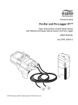
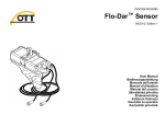
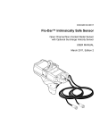
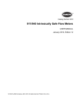
DOC026.53.00786
Flo-Dar™ Sensor
Open Channel Non-Contact Radar Sensor
with Optional Surcharge Velocity Sensor
USER MANUAL
July 2010, Edition 3
© HACH Company, . All rights reserved. Printed in the U.S.A.
Table of contents
Section 1 Specifications .................................................................................................................... 3
Section 2 General information ......................................................................................................... 5
2.1 Safety information ........................................................................................................................ 5
2.1.1 Use of hazard information................................................................................................... 5
2.1.2 Precautionary labels ........................................................................................................... 5
2.1.3 Confined space precautions ............................................................................................... 6
2.1.4 FCC regulations .................................................................................................................. 7
2.2 Product overview ......................................................................................................................... 7
2.2.1 Theory of operation............................................................................................................. 8
Section 3 Installation........................................................................................................................ 11
3.1 Unpack the instrument ............................................................................................................... 11
3.2 Mechanical installation............................................................................................................... 12
3.2.1 Site location guidelines ..................................................................................................... 12
3.2.2 Sensor installation............................................................................................................. 14
3.2.2.1 Assemble the clamps on the frame and wall bracket............................................... 17
3.2.2.2 Install the frame on the wall ..................................................................................... 19
3.2.2.3 Install the sensor on the frame................................................................................. 21
3.2.2.4 Align the sensor vertically—Flo-Dar without SVS .................................................... 21
3.2.2.5 Align the sensor vertically—Flo-Dar with SVS ......................................................... 22
3.2.2.6 Align the sensor horizontally .................................................................................... 23
3.2.2.7 Make a final alignment check................................................................................... 24
3.2.2.8 Optional extended depth sensor installation ............................................................ 24
3.2.3 Measure the sensor offset ................................................................................................ 26
3.2.4 Measure the pipe diameter ............................................................................................... 27
3.3 Electrical installation .................................................................................................................. 27
3.3.1 Wiring safety information .................................................................................................. 27
3.3.1.1 Electrostatic Discharge (ESD) considerations ......................................................... 27
3.3.2 Connection to the logger or controller ............................................................................... 28
Section 4 Operation .......................................................................................................................... 29
4.1 Install the Flo-Ware software on the PC .................................................................................... 29
4.2 Set up the FL900 Series Logger, Flo-Logger or Flo-Station ...................................................... 29
Section 5 Maintenance .................................................................................................................... 31
5.1
5.2
5.3
5.4
Preventative maintenance ......................................................................................................... 32
Cleaning the instrument ............................................................................................................. 32
Cable replacement..................................................................................................................... 33
Changing the sensor dessicant.................................................................................................. 33
5.4.1 Desiccant replacement procedure .................................................................................... 33
5.5 Hydrophobic filter description..................................................................................................... 34
5.6 Hydrophobic filter replacement procedure ................................................................................. 35
Section 6 Replacement Parts and Accessories ......................................................................... 37
6.1 Replacement Parts .................................................................................................................... 37
6.2 Accessories................................................................................................................................ 37
Section 7 Contact Information ....................................................................................................... 39
Section 8 Limited warranty ............................................................................................................. 41
1
Table of contents
2
Section 1
Specifications
Specifications are subject to change without notice
Flo-Dar sensor
Dimensions (W x L x D)
160.5 x 432.2 x 297 mm (6.32 x 16.66 x 11.7 in.); with SVS, D=287 mm (15.2 in.)
Weight
4.8 kg (10.5 lb)
Enclosure
IP68 waterproof rating, polystyrene
Operating temperature
–10 to 50 °C (14 to 122 °F)
Storage temperature
–40 to 60 °C (–40 to 140 °F)
Altitude
4000 m (13,123 ft) maximum
Power requirements
Supplied by FL900 Series Logger, Flo-Logger or Flo-Station
Polyurethane, 0.400 (±0.015) in. diameter
Interconnecting cable (disconnect at
both sensor and logger ends)
IP68
Standard length: 9 m (30 ft); maximum length: 305 m (1000 ft)
Method: Ultrasonic
Depth measurement
Standard operating range from Flo-Dar housing to liquid: 0 to 152.4 cm (0 to
60 in.)
Optional extended operating range from transducer face to liquid: 0 to 6.1 m
(0 to 20 ft) (with 43.18 cm (17 in.) deadband), temperature compensated
Accuracy: ±1% ±0.25 cm (±0.1 in.)
Method: Piezo resistive pressure transducer with stainless steel diaphragm
Surcharge depth measurement
Auto zero function maintains zero error < 0.5 cm (0.2 in.)
Range: 3.5 m (138 in.); overpressure rating: 2.5 x full scale
Method: Radar
Velocity measurement
Range: 0.23 m/s to 6.10 m/s (0.75 to 20 ft/s)
Frequency Range: 24.075 to 24.175 GHz, 15 mW (EIRP) max.
Accuracy: ±0.5%; ±0.03 m/s (±0.1 ft/s)
Certification
The Flo-Dar Transmitter is certified to the following requirements:
- Transmitter type: Field Disturbance Sensor
- Frequency: 24.125 GHz - Doppler pulse
- Maximum rated power output: 128 dbuV (average) @ 3 meters
Certified to:
FCC Part 15.245: FCC ID: VIC-FLODAR24
Industry Canada Spec. RSS210. v7: IC No.: 6149A-FLODAR24
Use of this device is subject to the following conditions:
1 There are no used serviceable items inside this device.
2
The user must install this device in accordance with the supplied installation
instructions and must not modify the device in any manner whatsoever.
3
Any service involving the transmitter must only be performed by
Hach Company.
4
The user must ensure that no one is within 20 cm of the face of the radar
transmitter when operating.
Flow measurement
Method
Based on continuity equation
Accuracy
± 5% of reading typical where flow is in a channel with uniform flow conditions
and is not surcharged, ± 1% full scale max.
3
Specifications
Surcharge conditions depth/velocity
Depth (standard with Flo-Dar Sensor)
Surcharge depth supplied by Flo-Dar sensor
Method: Electromagnetic
Velocity (with optional surcharge
velocity sensor)
Range: ±4.8 m/s (±16 ft/s)
Accuracy: ±0.15 ft/s or 4% of reading, whichever is greater
Zero stability: >±0.05 ft/s
FCC and Industry Canada Statements
Canadian Interference-causing Equipment Regulation, IECS-003, Class A
This Class A digital apparatus meets all requirements of the Canadian
Interference-causing Equipment Regulations.
Cet appareil numerique de la classe A respecte toutes les exigences du Pegulement sur
le materiel brouilleur du Canada
FCC PART 15, CLASS "A" Limits
The device complies with Part 15 of the FCC Rules. Operation is subject to the following
two conditions:
1. This device may not cause harmful interference, and
2. This device must accept any interference received, including interference that may
cause undesired operation.
Changes or modifications to this unit not expressly approved by the party responsible for
compliance could void the user’s authority to operate the equipment.
This equipment has been tested and found to comply with the limits for a Class A digital
device, pursuant to Part 15 of the FCC Rules. These limits are designated to provide
reasonable protection against harmful interference when the equipment is operated in a
commercial environment. This equipment generates, uses, and can radiate radio
frequency energy and, if not installed and used in accordance with the instruction manual,
may cause harmful interference to radio communications. Operation of this equipment in
a residential area is likely to cause harmful interference, in which case the user will be
required to correct the interference at the user’s own expense. The following techniques
of reducing the interference problems are applied easily.
1. Disconnect the equipment from it’s power source to verify that it is or is not the
source of the interference.
2. If the equipment is connected into the same outlet as the device with which it is
interfering, try another outlet.
3. Move the equipment away from the device receiving the interference.
4. Reposition the receiving antenna for the device receiving the interference.
5. Try combinations of the above.
4
Section 2
General information
2.1 Safety information
Please read this entire manual before unpacking, setting up, or operating this equipment.
Pay attention to all danger and caution statements. Failure to do so could result in serious
injury to the operator or damage to the equipment.
To ensure that the protection provided by this equipment is not impaired, do not use or
install this equipment in any manner other than that specified in this manual.
2.1.1 Use of hazard information
DANGER
Indicates a potentially or imminently hazardous situation which, if not avoided, will
result in death or serious injury.
DANGER
Indique une situation de danger potentiel ou imminent qui, si elle n'est pas évitée,
peut entraîner la mort ou des blessures graves.
WARNING
Indicates a potentially or imminently hazardous situation which, if not avoided,
could result in death or serious injury.
AVERTISSEMENT
Indique une situation de danger potentiel ou imminent qui, si elle n'est pas évitée,
pourrait entraîner la mort ou des blessures graves.
CAUTION
Indicates a potentially hazardous situation that may result in minor or moderate
injury.
ATTENTION
Indique une situation potentiellement dangereuse qui peut entraîner des blessures
mineures ou modérées.
Important Note: Indicates a situation which, if not avoided, may cause damage to the
instrument. Information that requires special emphasis.
Remarque importante: Indique une situation qui, si elle n'est pas évitée, peut provoquer
des dommages à l'appareil. Informations nécessitant une insistance particulière.
Note: Information that supplements points in the main text.
Remarque : Informations complétant des points du texte principal.
2.1.2 Precautionary labels
Read all labels and tags attached to the instrument. Personal injury or damage to the
instrument could occur if not observed.
This is the safety alert symbol. Obey all safety messages that follow this symbol to avoid potential injury. If on the
instrument, refer to the instruction manual for operation or safety information.
Ceci est le symbole d'alerte de sécurité. Se conformer à tous les messages de sécurité qui suivent ce symbole afin
d'éviter des blessures potentielles. Si apposés sur l'instrument, se référer au manuel d'utilisation pour le
fonctionnement ou les informations de sécurité.
5
General information
Electrical equipment marked with this symbol may not be disposed of in European public disposal systems after
12 August of 2005. In conformity with European local and national regulations (EU Directive 2002/96/EC),
European electrical equipment users must now return old or end-of life equipment to the Producer for disposal at no
charge to the user.
Note: For return for recycling, please contact the equipment producer or supplier for instructions on how to return
end-of-life equipment, producer-supplied electrical accessories, and all auxiliary items for proper disposal.
L'équipement électrique marqué de ce symbole ne devra pas être détruit dans les systèmes de
destruction publics Européens après le 12 août 2005. En conformité avec les dispositions européennes
locales et nationales (Directive EU 2002/96/EC), les utilisateurs européens d'équipements électriques
doivent maintenant renvoyer au fabricant pour destruction les équipements anciens ou en fin de vie,
sans frais pour l'utilisateur.
Remarque : Pour le retour à des fins de recyclage, veuillez contacter le fabricant ou le fournisseur
d'équipement pour obtenir les instructions sur la façon de renvoyer l'équipement usagé, les accessoires
électriques fournis par le fabricant, et tous les articles auxiliaires pour une mise au rebut appropriée.
This symbol, when noted on a product enclosure or barrier, indicates that a risk of electrical shock and/or
electrocution exists.
Si ce symbole ce trouve sur l’instrument, il indique la présence d’un danger de choc électrique ou d’électrocution.
This symbol, when noted on the product, identifies the location of the connection for Protective Earth (ground).
Ce symbole, lorsqu’il est apposé sur le produit, indique l’emplacement de la connexion de mise à la terre.
This symbol, when noted on the product, identifies the location of a fuse or current limiting device.
Lorsque ce symbole se trouve sur un produit, il indique l’emplacement d’un fusible ou autre protection contre les
surcharges.
This symbol, when noted on the product, indicated the presence of devices sensitive to Electro-static Discharge
(ESD) and indicated that care must be taken to prevent damage with the equipment.
Ce symbole, s'il figure sur le produit, indiqué la présence des dispositifs sensibles à la décharge électrostatique
(ESD) et la nécessité d'agir avec précaution pour éviter d'endommager l'équipement.
2.1.3 Confined space precautions
DANGER
Explosion hazard. Training in pre-entry testing, ventilation, entry procedures,
evacuation/rescue procedures and safety work practices is necessary before
entering confined spaces.
DANGER
Danger d'explosion. Une formation incluant des tests de pré-entrée, la ventilation,
les procédures d'entrée, les procédures d'évacuation/de sauvetage et des pratiques
de travail de sécurité est nécessaire avant d'entrer dans des espaces restreint.
Important Note: The following information is provided to guide users of Flo-Dar Sensors
on the dangers and risks associated with entry into confined spaces.
Remarque importante : Les informations suivantes sont fournies dans le but d'informer
les utilisateurs des capteurs Flo-Dar des dangers et des risques associés à l'accès aux
espaces confinés.
On April 15, 1993, OSHA’s final ruling on CFR 1910.146, Permit Required Confined
Spaces, became law. This new standard directly affects more than 250,000 industrial
sites in the U.S.A., and was created to protect the health and safety of workers in
confined spaces.
6
General information
Definition of a confined space:
A confined space is any location or enclosure that presents or has the immediate
potential to present one or more of the following conditions:
•
An atmosphere with less than 19.5% or greater than 23.5% oxygen and/or more than
10 ppm Hydrogen Sulfide (H2S).
•
An atmosphere that may be flammable or explosive due to gases, vapors, mists, dusts
or fibers.
•
Toxic materials which upon contact or inhalation, could result in injury, impairment of
health or death.
Confined spaces are not designed for human occupancy. They have restricted entry and
contain known or potential hazards. Examples of confined spaces include manholes,
stacks, pipes, vats, switch vaults, and other similar locations.
Standard safety procedures must always be followed prior to entry into confined spaces
and/or locations where hazardous gases, vapors, mists, dusts or fibers may be present.
Before entering any confined space check with your employer for procedures related to
confined space entry.
2.1.4 FCC regulations
Use of this device is subject to the following conditions:
•
There are no used serviceable items in this device.
•
The user must install this device in accordance with the supplied installation
instructions and must not modify the device in any manner whatsoever.
•
Any service involving the transmitter must only be performed by Hach Company.
•
The user must ensure that no one is within 20 cm of the face of the radar transmitter
when operating.
2.2 Product overview
The Flo-Dar Sensor measures the flow velocity and liquid depth in open channels using
radar and ultrasonic technology. The unit is designed to withstand submersion during
surcharge conditions. The optional surcharge velocity sensor provides velocity
measurements during surcharge conditions.
Figure 1 on page 8 shows the configuration of a Flo-Dar system in a non-hazardous
location.
7
General information
Figure 1 System overview
1
Flo-Dar sensor with optional surcharge velocity sensor
3
Mounting frame
2
Logger or controller
4
Non-hazardous environment
2.2.1 Theory of operation
The Flo-Dar Sensor is mounted above an open channel of water and measures the
surface velocity and depth from above the surface of the water. The two measurements
are used to calculate the flow rate.
During surcharge (submerged) conditions, a pressure transducer measures depth. The
optional surcharge velocity sensor (SVS) can be used to measure velocity during
surcharge conditions.
Surface velocity measurement
The surface velocity of the water is measured using radar technology. A radar beam is
transmitted from the sensor to the water surface at the center of the channel. A portion of
the signal is reflected back at a slightly different frequency. The difference in frequency,
known as the Doppler frequency, is directly proportional to the speed of the flow.
Proprietary algorithms are then used to calculate the average speed of the flow stream.
Note: The radar velocity sensor does not operate under surcharge conditions.
Velocity measurements during surcharge
The optional surcharge velocity sensor (SVS) is activated when the flow level rises to
within 7 inches of the sensor mounting frame and remains active until the flow falls to
7 inches below the sensor mounting frame. The mounting frame is installed 5 to 6 inches
above the crown of the pipe. This places the velocity-sensing electrodes at the correct
location in the flow below the elevation of the crown of the pipe.
The SVS measures velocity using an electromagnetic sensor that generates a magnetic
field. When the water passes through the magnetic field, a voltage is generated that is
directly proportional to the speed of the water passing the sensor.
8
General information
Depth measurement
The water depth is measured using an ultrasonic pulse echo sensor. An electronic pulse
is sent to the water surface and a portion of the signal is returned to the sensor. The
transit time to the surface and back is used to calculate the distance from the water
surface to the sensor. The pipe diameter is used to convert the distance to water depth.
The depth sensor on the Flo-Dar unit can measure distances up to 1.5 m (5 ft). For larger
channels, an extended range sensor is available to measure up to 6.1 m (20 ft).
During surcharge conditions, a pressure transducer in the Flo-Dar unit is used to
measure depth.
Flow calculations
The velocity and depth measurements are used with the pipe diameter to determine the
flow rate. The flow rate is calculated from the continuity equation (1):
(1) Flow rate = Average velocity × Area
where
Flow rate = volume of liquid that passes the sensor per unit time (e.g. 200 gallons per minute)
Average velocity = average velocity of the liquid, calculated using surface velocity
measurements and algorithms
Area = cross-sectional area of the liquid in the channel, calculated using the channel
dimensions and depth measurement.
9
General information
10
Section 3
Installation
DANGER
Explosion hazard. Trained personnel only must install or commission the
equipment.
DANGER
Danger d’explosion. Seul le personnel formé est autoriséà installer ou à mettre en
service l’équipement.
3.1 Unpack the instrument
The instrument components with options are shown in Figure 2.
Figure 2 Instrument components
1
Surcharge velocity sensor (SVS) (optional)
10 Clamp bolt, ¼-20 x 1 in. (8x)
2
Flo-Dar sensor
11 Anchor nut, 3/8-16 (2x)
3
Optional extended depth sensor
12 Anchor washer (2x)
4
Bubble level
13 Anchor nut, 3/8 x 2¼ in. (2x)
5
Cable connectors
14 Adjustable wall bracket
6
Spacer, 12-inch
15 Wall mount bracket
7
Spacer, 2¼-inch
16 Standard frame
8
Clamp half, threaded (2x)
17 Frame for extended depth sensor (optional)
9
Clamp half, not threaded (2x)
11
Installation
3.2 Mechanical installation
3.2.1 Site location guidelines
For best accuracy, install the sensor where the flow is not turbulent. An ideal location is in
a long, straight channel or pipe. Outfalls, vertical drops, baffles, curves or junctions cause
the velocity profile to become distorted.
Where there are outfalls, vertical drops, baffles, curves or junctions, install the sensor
upstream or downstream as shown in Figure 3 and Figure 4. For upstream locations,
install the sensor at a distance that is at least five times the pipe diameter or maximum
fluid level. For downstream locations, install the sensor at a distance that is at least ten
times the pipe diameter or maximum fluid level.
If the location contains a junction and the flow in one pipe is much higher, install the
sensor on the wall near the lower flow pipe.
Figure 3 Sensor location near an outfall, vertical drop or baffle
1
Acceptable upstream sensor location
5
Distance downstream: 10 x pipe diameter
2
Outfall
6
Vertical drop
3
Distance upstream: 5 x maximum level
7
Baffle
4
Acceptable downstream sensor location
12
Installation
Figure 4 Sensor location near a curve, elbow or junction
1
Acceptable upstream sensor location
3
Distance downstream: 10 x pipe diameter
2
Acceptable downstream sensor location
4
Distance upstream: 5 x pipe diameter
13
Installation
3.2.2 Sensor installation
CAUTION
Potential hearing loss risk. Hearing protection required. The level transducer emits
ultrasonic sound energy when powered. Ear protection must be worn when
working within 1 meter of this device. Do not point the transducer output towards
ears during installation, calibration and maintenance.
ATTENTION
Risque de perte auditive. Protections auditives requises. Une fois activé, le
transducteur de niveau émet une énergie ultrasonore. Des protections auditives
doivent être portées lors de toute intervention à moins d’un mètre de cet appareil.
Ne pointez pas la sortie du transducteur vers des oreilles lors d’opérations
d’installation, d’étalonnage et de maintenance.
WARNING
Explosion hazard. Installation of equipment into hazardous locations must be done
so that no friction can be generated between the Flow Meter and any surrounding
surfaces (Figure 1 on page 8).
ATTENTION
Risque d’explosion. L’installation de l’équipement dans des zones dangereuses
doit être effectuée de sorte qu’aucun frottement ne soit provoqué entre le
débitmètre et toute surface environnante (Figure 1 de la page 8).
Mount the Flo-Dar sensor above the open channel on the wall of the manhole. A pole is
available for retrieval of the Flo-Dar sensor without entry into the manhole.
For temporary installation, an optional Jack-bar is available (see Accessories on
page 41). Instructions are included with the Jack-bar.
14
Installation
The Flo-Dar sensor dimensions are shown in Figure 5 and Figure 6.
Figure 5 Flo-Dar sensor dimensions
1
Optional extended depth sensor
2
Minimum clearance for cable with extended depth sensor
3
Minimum clearance for cable
15
Installation
Figure 6 Flo-Dar sensor with SVS dimensions
1
16
Minimum clearance for cable
Installation
The dimensions of the standard frame for wall installation are shown in Figure 7.
Figure 7 Standard frame dimensions
1
22.8 in. with 2¼ in. spacer; 32.6 in. with 12 in. spacer
3.2.2.1 Assemble the clamps on the frame and wall bracket
Install the clamps on the frame and wall mount bracket before installation on the wall.
Prerequisites
•
Frame
•
Wall mount bracket
•
Clamps
•
Hardware—wall bracket, spacer, nuts and bolts
Procedure
1. Position two clamp halves (one with threads and one without threads) around the wall
mount bracket as shown in Figure 8.
2. Connect the clamp halves together with four bolts. Lightly tighten the bolts to
temporarily hold the clamp in position.
17
Installation
3. Position the other two clamp halves around the front end of the frame as shown in
Figure 8.
Note: In most cases the front of the frame will point toward the wall as shown in Figure 8 (see
also Figure 12 on page 23). If flow conditions require the sensor to point away from the wall,
use the 12-inch spacer and position the two clamp halves around the back end of the frame.
4. Connect the clamp halves together with four bolts. Lightly tighten the bolts to
temporarily hold the clamp in position.
Figure 8 Clamps assembled on wall bracket and frame
1
Adjustable wall bracket
5
Frame
2
Clamp half, threaded
6
Spacer
3
Clamp bolt, ¼–20 x 1 in.
7
Wall mount bracket
4
Clamp half, not threaded
18
Installation
3.2.2.2 Install the frame on the wall
DANGER
Explosion hazard. Review the safety information in 2.1.3 Confined space
precautions on page 6 before entering a confined space.
DANGER
Danger d'explosion. Revoyez les informations concernant la sécurité à la section
2.1.3 à la page 8 avant d'entrer dans un espace restreint.
Sensor location guidelines
Review the following guidelines to find the best location for the sensor.
•
Examine the upstream and downstream flow characteristics. Use a mirror if
necessary. Install the sensor above the water where the flow is steady. Do not install
the sensor where there are standing waves, pools or objects or materials that can
disrupt the flow profile.
•
If the upstream flow characteristics are acceptable, install the sensor on the upstream
wall of the manhole with the sensor pointing upstream. This location will make sure
that the measured flow is the same as the flow in the pipe and that the sensor cable
points away from the wall.
•
Install the sensor away from the sides of the pipe and in the very center of the flow
where the fluid is at the maximum depth.
•
Install the sensor in a location that is accessible for maintenance.
Prerequisites
•
Frame and wall mount bracket assembly (assembled in section 3.2.2.1 on page 17)
•
Anchors with nuts and washers
•
Tools: mirror, ruler or tape measure, marker
Procedure
Complete the steps to install the frame on the wall of the manhole above the flow. Be
sure to follow all codes and/or directives that are relevant to the location (refer to 3.2.1 on
page 12).
1. Make a mark on the wall that identifies the location of the top of the sensor frame
(Figure 9). The wall brackets will be installed above and below this mark.
•
Flo-Dar without SVS—make sure that when the sensor is in the frame, the radar
beam will not be blocked by the wall or channel (Figure 11).
•
Flo-Dar with SVS—the top of the sensor frame must be installed at an exact
distance above the top of the channel. For pipe diameters greater than 25 inches,
measure 5 inches from the top of the channel to the top of the frame. For pipe
diameters less than 25 inches, measure 6 inches from the top of the channel to
the top of the frame.
2. Position the wall mount brackets above and below this mark.
3. Attach the brackets to the wall using the supplied anchors. Install the anchors into
3/8-inch diameter holes at a depth of 1½ inches.
4. Connect the frame to the wall bracket with a spacer as shown in Figure 9. The
12-inch spacer may be necessary to position the sensor farther from the wall when
there is a large pipe lip.
19
Installation
Figure 9 Wall installation
1
Distance from crown of pipe to top of frame
3
Washer
2
Anchor
4
Nut
20
Installation
3.2.2.3 Install the sensor on the frame
The sensor fits in the frame in only one direction and locks in position when the bail on
the sensor is turned (Figure 10). The sensor can be removed from the frame and installed
without entering the manhole when the optional retrieval pole is used (see Accessories
on page 37).
Procedure
1. Make sure that the cable is tightly connected to the sensor.
2. Turn the bail to retract the locking bars on the sensor.
3. Position the sensor on the frame. The cable should point toward the center of
the manhole.
4. Turn the bail to lock the sensor on the frame (Figure 10).
Figure 10 Horizontal alignment
1
Bubble level
2
Bail
3.2.2.4 Align the sensor vertically—Flo-Dar without SVS
The sensor must be aligned vertically to make sure that the sensor is above the flow and
that the radar beam will not be blocked by the wall or pipe (Figure 11).
Procedure
1. Make an estimate of where a line that extends from the top of the radar lens
perpendicular to where the lens will point (Figure 11).
2. Loosen the clamp on the wall mount bracket and position the frame so that the radar
beam will point below the crown of the pipe by at least 1 inch (Figure 11). It may be
necessary to install the 12-inch spacer to extend the frame farther from the wall.
3. Tighten the clamp and measure the frame position. Make sure that the radar beam is
not blocked by the wall or pipe. If the beam is blocked, move the frame further away
from the wall using the 12-inch spacer or lower the frame.
21
Installation
Figure 11 Vertical alignment of Flo-Dar sensor
1
Spacer
2
Distance from crown of pipe to top of frame
3.2.2.5 Align the sensor vertically—Flo-Dar with SVS
The sensor must be aligned vertically to make sure that the sensor is above the flow
under normal full flow conditions and that the SVS is activated under surcharge
conditions.
Prerequisites
•
Ruler or tape measure
Procedure
1. Measure directly above the crown of the pipe to the top of the frame (Figure 9 on
page 20).
2. If the pipe lip is longer than 5½ inches, install the 12-inch spacer between the wall
mount bracket and the frame (Figure 12).
3. Loosen the clamp on the wall mount bracket and position the top of the frame above
the crown of the pipe at the specified distance:
22
•
6 inches for a pipe diameter that is less than 24 inches
•
5 inches for a pipe diameter that is equal to or larger than 24 inches
Installation
4. Tighten the clamp and measure the frame position again to make sure it is at the
correct position.
Figure 12 Vertical alignment of Flo-Dar sensor with SVS
1
Spacer
3
2
Distance from crown of pipe to top of frame
SVS sensor (optional)
3.2.2.6 Align the sensor horizontally
The sensor must be aligned horizontally to make sure that the sensor is centered over
the flow. If the pipe is not level and has a slope of 2 degrees or more, align the sensor to
be parallel with the surface of the water.
Prerequisites
•
Bubble level
Procedure
1. Remove the paper backing from the bubble level and attach the level to the sensor
(Figure 10 on page 21).
2. Loosen the clamps and tap the frame into position.
3. Tighten both clamps and measure the frame position to make sure it is at the correct
position.
23
Installation
3.2.2.7 Make a final alignment check
The correct vertical and horizontal alignment of the sensor is necessary for accurate
measurements.
1. Measure the vertical alignment (section 3.2.2.4 on page 21 or section 3.2.2.5 on
page 22) and make adjustments if necessary.
2. Measure the horizontal alignment (section 3.2.2.6 on page 23) and make
adjustments if necessary.
3. Repeat steps 1 and 2 until no further adjustments are necessary.
3.2.2.8 Optional extended depth sensor installation
The extended depth sensor (Figure 13) can be used when the pipe or channel depth
exceeds the standard level specifications (refer to Specifications on page 3).
Use the extended frame (Figure 14) in place of the standard frame, or mount the
extended depth sensor on the wall.
The extended depth sensor must be installed at least 18 inches above the crown of the
pipe for correct measurements. The extended depth sensor has a deadband zone of
17 inches where the sensor is not active.
Figure 13 Extended sensor dimensions
24
Installation
Figure 14 Extended frame dimensions
1
29.1 in. with 2¼ in. spacer; 38.8 in. with 12 in. spacer
Figure 15 Vertical alignment with extended depth sensor
1
Spacer
25
Installation
3.2.3 Measure the sensor offset
The sensor offset is the distance from the top of the frame to the bottom of the pipe or
channel. This distance will be entered into the software and is necessary for accurate
flow calculations.
If the extended depth sensor (section 3.2.2.8 on page 24) is installed on the wall without
the extended frame, the sensor offset is the distance from the face of the extended depth
sensor to the bottom of the pipe or channel.
Prerequisites
•
Rod
•
Tape measure
Procedure
1. Put the rod in the bottom of the pipe or channel and align it vertically with the frame
(Figure 16).
2. Make a mark on the rod to identify where the top of the sensor frame is.
3. Measure the distance from the bottom of the rod to the mark. This is the sensor
offset.
Note: If it is not practical to measure to the bottom of the pipe, measure the distance from the
crown of the pipe to the top of the frame (Figure 16). Add this distance to the pipe diameter to
get the sensor offset (sensor offset = pipe diameter + distance from crown of the pipe to top
of frame).
Figure 16 Sensor offset
1
Distance from crown of pipe to top of frame
2
Pipe diameter
26
3
Sensor offset
Installation
3.2.4 Measure the pipe diameter
The correct diameter of the pipe or channel is necessary for accurate flow calculations.
1. Measure the inside pipe diameter (I.D.) at three locations (Figure 17). Be sure that
the measurements are accurate.
2. Calculate the average of the three measurements. Record this number for use during
the software setup for the site.
Figure 17 Pipe diameter measurement
3.3 Electrical installation
3.3.1 Wiring safety information
When making any wiring connections to the instrument, the following warnings and notes
must be adhered to, as well as any warnings and notes found throughout the individual
installation sections. For more safety information refer to section 2.1 on page 5.
CAUTION
Always disconnect power to the instrument when making any electrical
connections.
Attention
Débranchez toujours l'alimentation de l'appareil avant toute connexion électrique.
3.3.1.1
Electrostatic Discharge (ESD) considerations
Important Note: To minimize hazards and ESD risks, maintenance procedures not
requiring power to the instrument should be performed with power removed.
Delicate internal electronic components can be damaged by static electricity, resulting in
degraded instrument performance or eventual failure.
The manufacturer recommends taking the following steps to prevent ESD damage to
your instrument:
•
Before touching any instrument electronic components (such as printed circuit cards
and the components on them) discharge static electricity from your body. This can be
27
Installation
accomplished by touching an earth-grounded metal surface such as the chassis of an
instrument, or a metal conduit or pipe.
•
To reduce static build-up, avoid excessive movement. Transport static-sensitive
components in anti-static containers or packaging.
•
To discharge static electricity from your body and keep it discharged, wear a wrist
strap connected by a wire to earth ground.
•
Handle all static-sensitive components in a static-safe area. If possible, use anti-static
floor pads and work bench pads.
3.3.2 Connection to the logger or controller
Connect the cable from the Flo-Dar sensor to the logger or the controller:
28
•
Logger–connect the cable from the Flo-Dar sensor to the sensor connector on the
logger. If the Flo-Dar sensor has the SVS component, connect the cable from the
SVS component to the sensor connector on the logger.
•
Controller–connect the cable from the Flo-Dar sensor to the correct terminal in the
controller. If the Flo-Dar sensor has the SVS component, connect the cable from
the SVS component to the correct terminal in the controller. Refer to the user
manual for the controller for the correct terminal locations.
Section 4
Operation
A portable computer with Flo-Ware software must be connected to the logger or station to
set up and collect data from the Flo-Dar sensor.
4.1 Install the Flo-Ware software on the PC
Procedure
1. Put the Flo-Ware CD into the CD drive on the PC.
2. Save the floware4.exe file to the hard drive on the PC.
3. Open the file to start the installation wizard and follow the on-screen instructions to
install the software.
4. Open and run the flodar.exe file. An installation wizard will start. Follow the on-screen
instructions to install the software.
4.2 Set up the FL900 Series Logger, Flo-Logger or Flo-Station
WARNING
Explosion hazard. The connection must be made to a 12 VDC battery-powered
logger or controller.
DANGER
Danger d'explosion. La connexion doit être établie avec un enregistreur ou un
transmetteur doté d'une batterie de 12 V CC.
Refer to the Flo-Ware user manual (DOC016.53.80112) for details on how to set up the
Flo-Dar sensor. The Flo-Ware user manual can be downloaded from www.Hachflow.com,
or through the Documents and manuals link in the Main screen of the Flo-Ware
software.
29
Operation
30
Section 5
Maintenance
DANGER
Explosion hazard. Only qualified personnel can conduct the tasks described in this
section of the manual.
DANGER
Danger d'explosion. Les opérations décrites dans cette section du manuel ne
doivent être effectuées que par du personnel qualifié.
DANGER
Explosion hazard. When using the retrieval pole, make sure to connect the
grounding strap to the ground lug on the barrier. The sensor must also be
connected to the barrier during maintenance activities. This is to prevent ignition
of explosive gases due to static discharge.
DANGER
Danger d'explosion. Lors de l'utilisation du pôle de récupération, assurez-vous de
connecter la languette de mise à la masse à la cosse de masse de la plaque. Le
capteur doit également être connecté à la plaque pendant les opérations de
maintenance. Ceci sert à éviter d'enflammer les gaz explosifs dus à la décharge
statique.
The safety of the transmitter may be impaired if any of the following conditions
have occurred:
•
visible damage
•
storage above 70 ºC for prolonged periods
•
exposure to severe transport stresses
•
previous installation
•
failure to operate properly
If any of these conditions have occurred, return the device to the manufacturer for
recertification.
CAUTION
Radar RF Exposure Hazard. Although the Flo-Dar microwave power level is very
small (~15 mW) and is well below government stated exposure limits for
uncontrolled environments, users of this product should follow proper safety
protocols for the handling of devices with radar frequency transmitters. Avoid
placing the head and other vital organ areas within the microwave beam (within 1
meter of the microwave aperture).
AVERTISSEMENT
Danger d'exposition à la RF radar. Même si la puissance des micro-ondes du
Flo-Dar est très faible (~15 mW) et est largement en dessous des limites
recommandées par le gouvernement pour les environnements non-contrôlés, les
utilisateurs de ce produit devront suivre des protocoles de sécurité appropriés
pour la manipulation des appareils équipés de transmetteurs ayant une fréquence
radar. Évitez de placer la tête et autres parties contenant des organes vitaux dans le
trajet d'un faisceau de micro-ondes (à 1 mètre du faisceau de micro-ondes).
Important Note: Delicate Instrumentation. Handle with care to prevent damage to the
microwave transmitter. Damaged transmitters can result in higher signal power levels,
which can interfere with essential terrestrial microwave links.
31
Maintenance
5.1 Preventative maintenance
Examine the Flo-Dar sensor on an annual basis to look for corrosion or damage that can
allow environmental gases into the interior. Make sure that no swelling, blistering, pitting
or loss of material has occurred on the upper and lower portions of the main plastic
enclosure, the depth module or the radome.
If the extended depth sensor is used, examine the enclosure and the four ¼-20 SS bolts.
If the surcharge velocity sensor (SVS) is used, make sure the unit is not corroded and the
labels are readable. Inspect the cable connectors for any damage or corrosion and
tighten all connectors in the system.
The only parts of the Flo-Dar system that can be replaced by the user are the bail
assembly and the cable. If the sensor becomes defective, it must be replaced as a
complete unit.
Check the electrical connections
Examine the cable connectors on an annual basis for corrosion and tightness. If
corrosion is found, clean and dry the connectors to make sure that no moisture is on the
connector pins. If corrosion is severe, replace the cables.
5.2 Cleaning the instrument
DANGER
Explosion hazard. Never attempt to wipe or clean the Flo-Dar or SVS sensor while
in a hazardous location. Do not use abrasives or high-pressure hoses or washers
to clean the sensors. Do not disturb the pressure port on the bottom of the sensor.
DANGER
Danger d'explosion. N'essayez jamais d'essuyer ou de nettoyer le Flo-Dar ou le
capteur SVS dans un emplacement dangereux. N'utilisez pas de produits abrasifs
ou de tuyaux sous pression ou d'appareils de nettoyage pour nettoyer les capteurs.
Ne dérangez pas le port sous pression situé dans le bas du capteur.
Regular cleaning is not necessary because the sensor does not contact the flow unless a
surcharge condition occurs. Examine the sensor after a surcharge to see if cleaning is
necessary.
Prerequisites
•
Retrieval pole with hook (optional, see Accessories on page 37).
Procedure:
1. Remove power to the sensor.
2. Put the hook on the retrieval pole for removal without manhole entry. Make sure the
grounding strap is on the pole.
3. Hook the bail on the sensor and turn the pole counter-clockwise to unlock the sensor
from the frame. Remove the sensor.
4. Remove any debris from the bottom of the sensor. Clean the external surface of the
sensor with mild soap and rinse with water.
5. If the Surcharge Velocity Sensor (SVS) is used, use 600 grit sand paper to lightly
sand the electrodes (small black dots). Use only light pressure when sanding or the
electrodes will become damaged.
6. Lower and position the sensor on the frame. Make sure that the cable points toward
the center of the manhole.
7. Turn the retrieval pole clockwise to engage the locking bars into the frame.
8. Apply power to the sensor.
32
Maintenance
5.3 Cable replacement
Procedure
1. Disconnect power to the sensor at the logger or controller.
2. Put the hook on the retrieval pole for removal without manhole entry. Make sure the
grounding strap is on the pole.
3. Hook the bail on the sensor and turn the pole counter-clockwise to unlock the sensor
from the frame. Remove the sensor.
4. Remove the cable clamp by removing the two Phillips screws on the sensor handle.
Remove the cable.
5. Install the new cable. Make sure that the connector is aligned properly and that no
debris or water gets into the connector.
6. Replace the cable clamp.
7. Lower and position the sensor on the frame. Make sure that the cable points toward
the center of the manhole.
8. Turn the retrieval pole clockwise to engage the locking bars into the frame.
9. Apply power to the sensor via the logger or controller.
5.4 Changing the sensor dessicant
The desiccant canister contains beads of silica gel which ensure proper operation of the
pressure transducer located in the Flo-Dar Sensor. When the beads are yellow, they can
absorb moisture from the air. When they are green, they are saturated and cannot absorb
any more moisture from the air, and they must be replaced immediately.
The cable assembly with desiccant hub is compatible with either the Flo-Logger or the
FL900 loggers. When using this cable assembly with the Flo-Logger, do not disconnect
the desiccant cartridge that is attached to the Flo-Logger itself.
Important Note: When the beads begin to turn green, replace or rejuvenate the beads.
Permanent damage to the sensor may occur if the desiccant is not maintained. Never
operate the sensor without the proper desiccant. When rejuvenating beads, remove them
from the canister and heat at 100-180 ºC (212-350 ºF) until the beads turn yellow. If the
beads do not turn yellow, replace them with new beads. Do not head the canister.
5.4.1 Desiccant replacement procedure
Note: Replacing the desiccant does not require that the desiccant container be removed from the
desiccant box.
1. Use a slight twisting motion to twist the bottom end-cap until its slots align with the
retaining clips (Figure 18 on page 34).
2. Gently remove the end cap by grasping it and pulling it straight out.
3. Pour the desiccant beads out of the canister.
4. Hold the canister up to the light and inspect the hydrophobic filter.
•
If you see a small, dim light spot while looking through the hole, the filter is in good
condition. If you see a bright light spot, the filter is probably torn. Replace the filter.
•
If the desiccant beads were completely saturated with water or the filter has saturated
with water or grease, replace the filter.
33
Maintenance
5. Refill the canister tube with yellow desiccant beads (Cat. No. 875500). Inspect the
O-ring (Cat. No. 5252) on the bottom cap for cracking, pits, or evidence of leakage.
Replace if necessary.
Note: Applying O-ring grease to new or dry O-rings improves the ease of insertion, sealing, and life
span of the O-ring.
6. Make sure that the O-ring is clean and free of dirt or debris before replacing the end
cap.
7. Reinstall the end cap.
Figure 18 Removing the bottom end cap
1
End cap
3
Retaining clip
2
Retaining clip slots
4
Dessicant container
5.5 Hydrophobic filter description
A single Teflon® hydrophobic filter (Cat. No. 3390) is installed in the top of the canister to
prevent liquid from entering the vent tube.
For best performance and to avoid grease buildup on the filter during submergence or
surcharge conditions, hange the canister vertically so that the end cap points downward
(Figure 18).
Note: The hydrophobic filter may need replacement at any time the cartridge is submerged or
exposed to excess moisture. Refer to Hydrophobic filter replacement procedure on page 35.
34
Maintenance
5.6 Hydrophobic filter replacement procedure
1. Disconnect the tubing from the top of the desiccant canister.
2. Unscrew the hex-head tubing nipple from the top of the canister and discard the old
filter.
3. Discard any remnants of Teflon tape from the nipple threads. Apply two turns of
Teflon tape (Cat. No. 1085145) to the threads, pulling the tape into the threads until it
conforms to the shape of the threads.
4. Place a new filter over the hole. Make sure that the smooth side of the filter faces the
inside of the canister (Figure 19).
5. Place the threaded nipple on top of the filter.
6. With a slight pressure, press the filter into the hole with the nipple threads and begin
threading the nipple into the hole. The filter will deflect upward and feed completely
into the thread until it disappears. The filter must rotate with the nipple as it is
threaded into the cap. If it does not, it is torn. Start over with a new filter.
7. Inspect the installation. In the upper cap, a small, dim light spot should be visible
when held up to the light. A bright spot indicates a torn filter. Start over with a new
filter.
Figure 19 Replacing the Hydrophobic Filter
1
Filter, smooth side down
2
Hex-head tubing nipple
3
Finished assembly
35
Maintenance
36
Section 6
Replacement Parts and Accessories
6.1 Replacement Parts
Description
Bail assembly
Cable assembly, 30 ft, connector on one end (includes junction box, desiccant, and
potting kit)
Cable assembly, 30 ft, connector on both ends
Cable assembly, 60 ft, connector on one end (includes junction box, desiccant, and
potting kit)
Cable assembly, 60 ft, connector on both ends
Cable assembly, 100 ft, connector on one end (includes junction box, desiccant, and
potting kit)
Cable assembly, 100 ft, connector on both ends
Desiccant cartridge assembly
Catalog Number
800014901
FDJCTBOXCBL-030
FD9000CBL-030
FDJCTBOXCBL-060
FD9000CBL-060
FDJCTBOXCBL-100
FD9000CBL-100
8542000
Flo-Dar sensor
890004901
SVS sensor, 30-ft cable, replacement only
600006203
Wall mount assembly, standard frame (includes frame and hardware)
800016701
Wall mount assembly, extended frame (includes frame and hardware)
800016201
Wall mount hardware
800015401
Note: Contact customer service for additional cable length options
6.2 Accessories
Description
Desiccant beads, bulk, 1.5 pound canister
Hook for sensor retrieval pole
Catalog Number
8755500
510012701
Sensor retrieval pole, 8–24 ft
245000501
Temporary mount assembly, standard frame, 34 in. to 52 in. manhole
800016401
Temporary mount assembly, standard frame, 52 in. to 70 in. manhole
800016402
Temporary mount assembly, standard frame, 70 in. to 88 in. manhole
800016403
Temporary mount assembly, standard frame, 89 in. to 107 in. manhole
800016404
Temporary mount assembly, extended frame, 34 in. to 52 in. manhole
800016301
Temporary mount assembly, extended frame, 52 in. to 70 in. manhole
800016302
Temporary mount assembly, extended frame, 70 in. to 88 in. manhole
800016303
Temporary mount assembly, extended frame, 89 in. to 107 in. manhole
800016304
37
Replacement Parts and Accessories
38
Section 7
Contact Information
Ordering information for the U.S.A.
Telephone:
800-368-2723
Fax:
301-874-8459
Address:
Hach Company
4539 Metropolitan Court
Frederick, MD 21704-9452
U.S.A
Email: [email protected]
Information Required
•
Hach account number (if available)
•
Billing address
•
Your name and phone number
•
Shipping address
•
Purchase order number
•
Catalog number
•
Brief description or model number
•
Quantity
European Union
Flow-Tronic
Rue J.H. Cool 19a
B-4840 Welkenraedt
Belgium
Tel: + -32-87-899799
Email: [email protected]
www.flow-tronic.com
Outside the U.S.A. and EU
Hach Company maintains a worldwide network of dealers and distributors. To locate a
representative, send an email to [email protected] or visit www.hachflow.com.
Technical Support
Technical and Customer Service Department personnel are eager to answer questions
about our products and their use. In the U.S.A., call 1-800-368-2723. Outside the U.S.A.
and Europe, send an email to [email protected] or call 301-874-5599.
Repair Service
Authorization must be obtained from Hach Company before sending any items for repair.
To send the monitor to the factory for repair:
1. Identify the serial number of the monitor unit.
2. Record the reason for return.
3. Call the Customer Service Department (1-800-368-2723) and get a Service Request
Number (SRN) and shipping label.
4. Use the shipping label provided and ship the equipment in the original packaging if
possible.
Note: Do not ship manuals, computer cables, or other parts with the unit unless they are
required for repair.
5. Make sure the equipment is free from foreign debris and is clean and dry before
shipping. Sensors returned without cleaning will be charged a fee.
39
Contact Information
6. Write the SRN number on the shipping box.
7. Make sure that all return shipments are insured.
8. Address all shipments to:
Hach Company
5600 Lindbergh Drive - North Dock
Loveland, Colorado, 80539-0389
U.S.A.
Attn: SRN#XXX
40
Section 8
Limited warranty
Manufacturer warrants all products of its manufacture to be free from defects in workmanship and
material under normal use and service. This warranty extends for a period of twelve (12) months after
date of shipment, unless altered by mutual agreement between the purchaser and manufacturer prior to
the shipment of the product. If this product is believed to be defective, purchaser shall notify
manufacturer and will return the product to the manufacturer, postage paid, within twelve (12) months
after date of shipment by the manufacturer. If the purchaser believes the return of the product to be
impractical, manufacturer shall have the option, but will not be required, to inspect the product wherever
located. In any event, if the purchaser requests the manufacturer visit their location, the purchaser
agrees to pay the non-warranty expenses of travel, lodging and subsistence for the field service
response. If the product is found by the manufacturer’s inspection to be defective in workmanship or
material, the defective part or parts will either be repaired or replaced, at manufacturer’s election, free of
charge, and if necessary the product will be returned to purchaser, transportation prepaid to any point in
the United States. If inspection by the manufacturer of such product does not disclose any defect of
workmanship or material, manufacturer’s regular service repair charges will apply. Computing devices
sold but not manufactured by Marsh-McBirney, Inc. are covered only by the original manufacturer’s
written warranty. Hence, this warranty statement does not apply.
The foregoing warranty is manufacturer’s sole warranty, and all other warranties, express,
implied or statutory, including any implied warranty of merchantability or fitness for a particular
purpose, are negated and excluded. The foregoing warranty is in lieu of all other warranties,
guarantees, representations, obligations or liabilities on the part of the manufacturer. Purchaser’s
sole remedy and manufacturer’s sole obligation for alleged product failure, whether under warranty claim
or otherwise, shall be the aforestated obligation of manufacturer to repair or replace products returned
within twelve months after date of original shipment. The manufacturer shall not be liable for, and the
purchaser assumes and agrees to indemnify and save harmless the manufacturer in respect to, any loss
or damage that may arise through the use by the purchaser of any of the manufacturer’s products.
41
Limited warranty
42