1
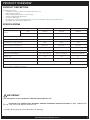
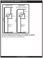
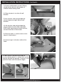
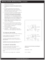
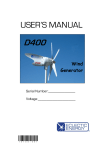
HEAT-FLO™ GAS HEATER BY BROMIC INSTALLATION, INSTRUCTION AND SERVICE MANUAL SUITABLE FOR GAS RADIANT HEATER MODELS: HEAT-FLO™ - 2 TILE, 3-TILE, 5-TILE ! DANGER If you smell gas: 1. Shut off gas to the appliance 2. Extinguish any open flame 3. If odor continues, keep away from the appliance and immediately call your gas supplier or fire department. ! Version 1.0 AUS WARNING: For Outdoor or Amply Ventilated area use and for NON DOMESTIC INDOOR APPLICATION ! WARNING Do not store or use petrol or other flamable vapor and liquids in the vicinity of this or any other appliance. An LP-cylinder not connected for use shall not be stored in the vicinity of this or any other appliance. ! WARNING: Improper installation, adjustment, alteration, service or maintenance can cause property damage, injury or death. Read the installation, operating and maintenance instructions thoroughly before installing or servicing this equipment. ! IMPORTANT This manual contains important information about the assembly, operation, and maintenance of Heat-Flo mounted Heaters and is not for mobile stand operations. Please pay close attention to the important safety information shown throughout this instruction manual. Any safety information will be accompanied by the following safety alert symbols: ! DANGER, ! WARNING, ! IMPORTANT • READ THIS MANUAL CAREFULLY before installing or servicing this product. • Improper installation, operation, or maintenance can result in death, severe injury, or property damage. • Installation must be carried out by Authorised person/s in accordance with AS5601-2010 Gas Installation Code. • This appliance is to be used ONLY for outdoor and nonresidential indoor use (minimum room volume must be 250m3) • When installed outdoors this appliance MUST be protected from rain. Head Office: 1 Suttor Street, Silverwater, Sydney, NSW 2128 Australia Telephone: 1300 276 642 (within Australia) or +61 2 9748 3900 (from overseas) Fax: +61 2 9748 4289 Email: [email protected] Web: www.bromicplumbing.com.au Note: Bromic Plumbing & Gas reserves the right to make changes to specifications, parts, components and equipment without prior notification. This Installation, operation and service manual may not be reproduced in any form with prior written consent from Bromic Plumbing & Gas 2 www.bromicplumbing.com.au CONTENTS IMPORTANT NOTES & WARNINGS 4 PRODUCT OVERVIEW 5 PRODUCT DESCRIPTION 5 SPECIFICATIONS 5 INSTALLATION REQUIREMENTS 6 GAS REQUIREMENTS 7 INSTALLATION CLEARANCES 7 INSTALLATION INSTRUCTIONS 8 HEATER INSTALLATION INSTRUCTIONS 8-10 SUITABLE AREAS FOR INSTALLATION 11-13 TROUBLE SHOOTING 14 SERVICING 15 www.bromicplumbing.com.au 3 IMPORTANT NOTES AND WARNINGS WARNING • • • • THIS APPLIANCE SHALL NOT BE INSTALLED OR USED IN RESIDENTIAL DOMESTIC INDOOR AREAS DO NOT PLACE ARTICLES ON OR AGAINST THIS APPLIANCE DO NOT USE OR STORE FLAMMABLE MATERIALS NEAR THIS APPLIANCE DO NOT SPRAY AEROSOLS OR FLAMMABLE MATERIALS IN THE VACINITY OF THIS APPLIANCE WHILE IT IS IN OPERATION Failure to follow the warnings and instructions in this manual could result in severe personal injury, death or property damage. • • • • • • • • • • • • • • • • 4 This Installation, Operation and Service manual should not be removed from the site of installation. This Appliance is for outdoor and non-residential indoor areas only. (see attached diagrammatical representations of outdoor areas “Appendix A”). Any guard or other protective device removed for servicing (conducted by an authorised person) must be replaced before operating the heater. Adults and children should stay away from high temperature surfaces to avoid burns or other serious personal injury. Children should be carefully supervised when they are in the area of the heater. Clothing or other flammable materials should not be hung from the heater or placed on or near the heater. Do not perform maintenance until heater has been turned off, power disconnected, and heater temperature has cooled to room temperature. Do not expose the burner to water or moisture. The appliance is to be protected from rain. Do not use the heater if any of these parts are exposed to water until the appliance is inspected or repaired by an authorised service person. The installer is to ensure that the requirements of the local authority, local gas fitting regulations, municipal building codes, and any other relevant statutory regulations are carried out. Certain materials or items, when stored under or near the appliance, will be subjected to radiant heat and could be seriously damaged. Ensure combustible materials eg. overhead structures, walls, floors, furniture, fixtures and plants must be kept 1100mm from the top and side. The whole gas system, hose assembly, regulator, pipes, and burner should be inspected for damage and leaks before use and at least annually by an authorized person for the life of the heater. All leak tests should be done with a soap solution. Never use an open flame to check for leaks. Do not use the heater until all connections have been leak tested by an authorised person. Inspect the hose assembly before each use of the appliance. The hose assembly must be replaced prior to the appliance being put into operation if there is evidence • • • • • • • • • • • • • • • • • • • • • • of excessive abrasion or wear, or if the hose is damaged. The replacement hose assembly must be AGA approved. The hose assembly is not to be located in areas where the hose may be subject to accidental damage. This radiant heater is NOT intended to be installed on recreational vehicles and/or boats. Repair to be carried out ONLY by an authorised person. Improper installation, adjustment, or alteration can cause personal injury, property damage, or even death. Do not attempt to alter the unit in any manner. Ensure that the heater is never used without an AGA approved pressure limiting regulator Remove transit protection before use. Never operate the heater in an explosive environment such as areas where petrol or other flammable liquids or vapours are stored. Turn off the gas supply immediately if smell of gas is detected. Do not paint any surface of the heater. Control compartment, burner and circulation air passageways of the heater must be kept clean. Frequent cleaning may be required as necessary. Turn Gas Supply off when not in use. Check the heater immediately if any of the following occurs: »» The heater does not reach temperature. »» The burner makes popping noise during use (a slight noise is normal when the burner is ignited or extinguished). Young children should be supervised to ensure that they don’t play with the appliance. This appliance is not intended for use by young or infirm persons unless they have been adequately supervised by a responsible person to ensure that they can use the appliance safely. Check for damage to the appliance regularly. If damage to the cord, plug or appliance is suspected, discontinue use immediately and contact the supplier or qualified person for repair. If the cord, plug or appliance is damaged, unplug from the outlet, discontinue use immediately, and only an authorised person or similar may repair the unit. Avoid inhaling fumes emitted from the heater’s first use. Smoke and odour from the burning of oils used in manufacturing will appear. Both the smoke and odour will dissipate after approximately 30 minutes. Ensure that a watertight seal is maintained on the electrical control box at all times Regularly check for damage to the rubber seals. If damage to the rubber seals is suspected, discontinue use immediately, switch off power and contact the place of purchase or authorised service technician for repair. Radiant gas heaters are sensitive to wind. Care must therefore be taken to ensure Bromic Heat-flo heaters are not installed in windy locations and that the heaters are protected from wind www.bromicplumbing.com.au PRODUCT OVERVIEW PRODUCT DESCRIPTION All • • • • • • • Models Feature: Suitable for outdoor and non-residential indoor use* Manual Piezo Ignition Flame safeguard system to ensure safety Includes wall-mounted bracket 12 Months Warranty** Designed for commercial applications* such as restaurants, warehouses and factories Australian Gas Association approved SPECIFICATIONS No. of Tiles 2 Tiles 3 Tiles 5 Tiles LPG* 2620110 2620100 2620120 Natural Gas* 2620111 2620101 2620121 Heat Deflector Part no. 2620164 2620162 2620170 HEAT-FLO™ Surround Part no. 2620171 2620161 2620172 Heat Output on LPG (Mj) (BTU) 16Mj 25Mj 45Mj Approximate area heated in m2 up to 12m2 up to 16m2 up to 25m2 Gas connection 3/8” SAEM 3/8” SAEM 3/8” SAEM 135 hours approx. 90 hours approx. 50 hours approx. 387 x 334 x 180mm 499 x 334 x 180mm 695 x 334 x 180mm Weight (kg) 3.9 5.8 7.1 Ceiling clearance required (m) *without deflector 1.1 1.1 1.1 Part no. Gas consumption per 45kg Dimensions (WxHxDmm) Stand dimensions (WxDxH) 480 x 430 x 2100mm n/a *Must only be installed by a licenced technician *Must complete “Installation Checklist” ! IMPORTANT THIS APPLIANCE IS NOT APPROVED FOR INDOOR DOMESTIC USE • CLEARANCE TO COMBUSTIBLE MATERIAL AROUND OVERHEAD RADIANT HEATERS are kept 1100mm from the top, side, front and 100 mm from the rear ** Contact local agent for more information on warranty www.bromicplumbing.com.au 5 INSTALLATION REQUIREMENTS This appliance shall only be used in above ground open-air situations with: • natural ventilation • without stagnant areas • where gas leakage and products of combustion are rapidly dispersed by wind and natural convection Any enclosure in which the appliance is used shall comply with one of the following: 1. An enclosure with walls on all sides, but at least one permanent opening at ground level (ref. Appendix A, Example 1) 2. Within a partial enclosure that includes an overhead cover and no more than two walls (ref. Appendix A, Example 2) 3. Within a partial enclosure that includes an overhead cover and more than two walls, the following shall apply: • At least 25% of the total wall area is completely open (ref. Appendix A, Example 4), and • At least 30% of the remaining wall area is open and unrestricted (ref. Appendix A, Example 4) 4. In the case of Using this appliance/s for non-residential indoor use: • This appliance must not be used in a room smaller than 250 cubic meters (ref. Appendix A, Example 5) • This appliance must only be used in a well ventilated area (ref. Appendix A, Example 5) Note: The definition of outdoors is an above ground openair situation with natural ventilation, without stagnant areas, where gas leakage and products of combustion are rapidly dispersed by wind and natural convection. Location of Hose Where a hose assembly is used is to be as short as practicable and not located in areas where the hose may be subject to accidental damage or be in contact with any surface of the burner Where a hose assembly is used inspect the hose assembly before each use of the appliance. Where a hose assembly is used the hose assembly must be replaced prior to the appliance being put into operation if there is evidence of excessive abrasion or wear, or if the hose is damaged, and that the replacement hose assembly shall be AGA approved 6 www.bromicplumbing.com.au INSTALLATION REQUIREMENTS CONTINUED... WITHOUT HEAT DEFLECTOR 1100mm CEILING WITH HEAT DEFLECTOR (heat deflector required for low-clearance installations) CEILING 600mm* 300mm 2900mm 3400mm 300mm 2000mm minimum clearance FLOOR 2000mm minimum clearance FLOOR Do not use it for domestic indoor use or in an enclosed area. Always ensure that adequate fresh air ventilation is provided. The base of the heater be no less than 2m above floor level. www.bromicplumbing.com.au 7 INSTALLATION INSTRUCTIONS Heat Flo LPG and Natural Gas Fixed Heater Installation and Operating Instructions Note the Bromic Heat Flo LPG and Natural Gas Fixed Heater is to be installed and used in accordance with AS5601-2010 Gas installations and must be installed by an authorised person. The base of the heater to be no less than 2 m above floor level. Mounting the Heat Flo LPG and Natural Gas Fixed The wall on which the heater is to be mounted must be capable of supporting the weight of the heater. Place the mounting bracket in position and mark the fixing hole location on the wall. The heater shall be firmly and securely attached to the wall. During installation direct appliance away from wind direction For Brick and Masonary use 8mm Dynabolts ( or equivalent) For Stud wall use suitable screw fixings no less than 38 mm in length The tilt switch operates as a “switch off” function. Therefore the functional tilt switch must not be disconnect or removed from the appliance. The heater can now be hung on the bracket. Slacken off the securing nuts and slide the heater into the U bolts and tighten the nuts. Bromic, in accordance with AS5601-2010, recommend the following installation heights; Commercial – indoors – no less than 2.5 metres off the ground Commercial/Residential – outdoors – No less than 2 metres off the ground. 8 www.bromicplumbing.com.au INSTALLATION INSTRUCTIONS CONTINUED... 1) Secure wall bracket to wall. Fitting needs to be able to hold weight of Heatflo Heater being used. 2) Place heater in to slots of wall bracket 3) Use washer and nut provided to secure heater to right side of wall bracket. 4) Use washer and nut provided to secure heater to left side of bracket. BOTH Nuts need to be used to ensure correct function of the heater. 5) Ensure heater is secure and can not move in the bracket 6) Connect gas to heater and test for leaks *2 Bolts either side must be used to ensure heater mount is stable & tilt switch remains parallel to ground. If switch is not parallel heater will not remain alight. WRONGRIGHT www.bromicplumbing.com.au 9 INSTALLATION INSTRUCTIONS CONTINUED... 1. Connecting the Gas to the Bromic Heat Flo Natural Gas fixed Heater 2. An approved manual isolating valve must be fitted before the heater in accordance with AS 5601 White Rodger 3. The outlet connection of the heater is a R½ BSP tapered male. Connect the AGA approved Gas Governor AGA number 5149 to the R½ BSP tapered male thread 4. For connection between the approved manual isolating valve and the out let of the heater use nominal 1/2 OD copper tube and flared connection in accordance with AS5601-2012 Gas installations or an AGA approved 10mm class B gas hose. It is recommended that the maximum length of the hose assembly as short as practicable and not more than 900 mm. 5. Tighten all the connections and then turn on the gas supply. Check for any leakage with a solution of soapy water. 6. Do not use a naked flame to check for leaks. 7. Check gas pressure at the test point to ensure the burner pressure to the heater is 0.86 kpa when the heater is operating 8. Ignition Operations ( see ignition operation diagram) 9. Important Direct appliance away from wind direction during lighting and operations TO TURN ON THE HEATER 1) Turn ON the valve on the gas supply completely 2) Direct appliance away from wind direction during lighting and operations 3) Pull the string down and maintain tension for around 10 seconds The tiles should start to become red. 4) Release the string. If the heater does not ignite wait 30 seconds and repeat point 2 and 3 TO TURN OFF THE HEATER 10 1) Pull the string down with a quick tug ( to activate the tilt switch) and release The tiles should change colour from red to black Please note the following operating gas pressures; 2) If the heater does not switch off try point 1 again Natural Gas – 1Kpa 3) Turn OFF the gas supply valve completely LPG – 2.75Kpa www.bromicplumbing.com.au APPENDIX A www.bromicplumbing.com.au 11 APPENDIX A CONTINUED... 12 www.bromicplumbing.com.au APPENDIX A CONTINUED... www.bromicplumbing.com.au 13 TROUBLESHOOTING SYMPTOM POSSIBLE CAUSE CORRECTIVE ACTION Heater will not turn on 1. No gas 1. Have authorised gas fitter check gas supply Heater turns on, but then turns off 1. Drafty conditions 1. • • Check and set gas pressure Check and clear obstruction to burner venturi and injectors 2. Discontinue use in high winds 3. Check that tilt switch is not engaged No gas 1. 2. 3. 4. Low ceramic tile surface temperature 1. Low manifold gas pressure 2. Low gas inlet pressure 3. Orifice partially blocked with foreign matter 4. Combustion by-products not adequately ventilated 5. Manifold misaligned from excessive torque applied on pipe at installation 6. Gas supply piping too small 7. Foreign matter in venturi tube 1. Adjust valve regulator until 1kpa for natural gas, or 2.75kpa for propane is obtained 2. Adjust main supply regulator until at least 1.25kpa for natural gas or 3kpa for propane precedes heater’s control assembly 3. Clean orifice 4. Provide adequate ventilation of by-products 5. Replace manifold 6. Increase gas pressure or replace piping 7. Remove with bottle brush Gas odour 1. 2. 3. 4. 5. Loose pipe connection Defective regulator Defective manual shut-off valve Defective gas control valve Loose flexible hose 1. Check all connections with soap solution and tighten where necessary 2. Replace regulator 3. Replace manual shut-off valve 4. Replace gas control valve 5. Tighten flexible hose Burning of gas/air mixture inside burner casting (flashback) 1. 2. 3. 4. Separation of ceramic tiles Ceramic tile(s) cracked Heater mounted at incorrect angle Excessive drafts 1. Replace burner assembly 2. Replace burner assembly 3. Check angle of heater. See heater nameplate. 4. Shield or relocate heater. Control assembly is overheating 1. Heater not mounted correctly 1. Mount wall bracket / control housing against a vertical flat surface, following the instructions outlined in the installation section of this manual. Always use supplied parts to mount heater. Carbon formation on ceramic tile surface of burner 1. 2. 3. 4. 1. 2. 3. 4. 14 Air in gas line Manual shut-off valve closed Regulator sticking Regulator reversed Misaligned orifice Obstruction in venturi tube Low gas pressure Wrong gas supplied to heater www.bromicplumbing.com.au 1. 2. 3. 4. Purge line Open valve Replace regulator Remove and install properly Consult sales agent or factory Clean with bottle brush Provide required pressure Check label for type of gas required SERVICING WARNING Servicing shall be carried out by authorized personnel only. During normal operations this heater does not require a programmed maintenance schedule. If service is required, remove the reflector hood, and burner mesh assembly to access the ignition system and gas valve. Replace the faulty item with correct approved component from the list below. GAS VALVE Beckley Forge valve NG22.18-DO thermoelectric flame safeguard controls is only for the 5 tile heater MP model 401 AGA approval number 3771 thermoelectric flame safeguard controls for 2 & 3 tile heaters IGNITION A piezoelectric button is used for ignition Gas Governor An AGA approved Bromic Gas Governor AGA number 5149 LPG Gas Regulator An AGA approved or UL approved LPG gas Regulator with outlet pressure of 2.75 Kpa. Not supplied with the LPG wall mounted model. TILT SWITCH Ubukata industries UG-7X www.bromicplumbing.com.au 15