1
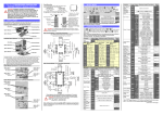
TUNGSTEN SMART-HEAT™ ELECTRIC DIMMER CONTROLLER BY BROMIC USER MANUAL ! IMPORTANT READ THIS MANUAL CAREFULLY. SEE INSIDE COVER FOR IMPORTANT INFORMATION ABOUT THIS MANUAL.KEEP INSTRUCTION WITH APPLIANCE FOR FUTURE REFERENCE. Version 1.0 US ! IMPORTANT This manual contains important information about the installation, and operation of Tungsten Electric controller. Please pay close attention to the important safety information shown throughout this instruction manual. Any safety information will be accompanied by the following safety alert symbols: ! DANGER, ! WARNING, ! IMPORTANT • READ THIS MANUAL CAREFULLY before installing or servicing this product. • Improper installation or operation can result in death, severe injury, or property damage. • Use this controller only as described in this manual. Any other use not recommended by the manufacturer may cause fire, electric shock, or injury to persons • This controller is intended for fixed installation with 120 volt, 208 volt or 240 volt power supply. • Installation MUST be carried out by a licensed and authorised technician in accordance with local electrical codes. • For Commercial Use Only NOTE: IMPORTANT INSTRUCTIONS, SAVE THESE INSTRUCTIONS BROMIC HEATING Head Office: 1 Suttor Street, Silverwater, Sydney, NSW 2128 Australia Telephone: 1300 276 642 (within Australia) or +61 2 9748 3900 (from overseas) Fax: +61 2 9748 4289 Email: [email protected] Web: www.bromicheating.com Note: Bromic Heating reserves the right to make changes to specifications, parts, components and equipment without prior notification. This Installation, operation and service manual may not be reproduced in any form with prior written consent from Bromic Heating. 2 www.bromicheating.com CONTENTS IMPORTANT NOTES & WARNINGS 4 PRODUCT OVERVIEW 5 INSTALLATION & OPERATION 6-8 www.bromicheating.com 3 IMPORTANT NOTES AND WARNINGS ! WARNING • This appliance must only be used on a 120, 208 or 240 Volt AC Single Phase electricity supply. • This controller is NOT intended to be installed on recreational vehicles and/or boats. • Read all instructions before installing or using this heater • Use this controller only as described in this manual. Any other use not recommended by the manufacturer may cause fire, electric shock, or injury to persons. • Do not run cord under carpeting. Do not cover with throw rugs, runners or the like arrange cord away from traffic area and where it will not be tripped over • Improper installation, adjustment, or alteration and failure to follow the warnings and instructions in this manual could result in severe personal injury, death or property damage. • A controller has hot and arcing or sparking parts inside. Do not use it in areas where gasoline, paint or flammable liquids are used or stored. • The manufacturer is not responsible for any damage that could happen from improper use. The manufacturer emphasises that this controller should be used in a responsible manner and that all procedures, warnings, and safety instructions contained in this booklet be followed strictly. • This Installation and Operation manual should not be removed from the site of installation. Installer should leave manual with the customer for future reference. • Any guard or other protective device removed for servicing (conducted by an authorised person) must be replaced before operating the controller. • If the controller has not been used, or will not be used, for a long period of time, disconnect power supply • A means for disconnection of the controller must be incorporated in the fixed wiring according to the local electrical codes. • This controller is not intended for use in bathrooms, laundry areas and similar indoor locations. Never locate controller where it may fall into a bathtub or other water container. • Do not install the controller directly near a bathtub, shower or swimming pool. Any switches or controls must not be within reach of a person in the bathtub, shower or swimming pool. • Extreme caution is necessary when any controller is used by or near children or invalids and whenever the controller or heater is left operating and unattended. • This controller is not intended for use by persons (including children) with reduced physical, sensory or mental capabilities, or lack of experience and knowledge, unless they have been given supervision or instruction concerning use of the appliance by a person responsible for their safety. • Keep packaging materials out of reach of children • MAINTENANCE/ REPAIR • Installation and repair must be carried out by a qualified & licenced service person only. The controller should be inspected before use and at least annually serviced & inspected by a qualified & licenced service person. • Do not perform maintenance until controller has been turned off and power disconnected. Children and adults should be alerted to the hazards of electrocution and should stay away to avoid serious personal injury • Check for damage to the controller regularly. If damage to the appliance is suspected, discontinue use immediately and contact the supplier or qualified person to repair. • Children should be carefully supervised when they are in the area of the controller. • If the supply cord is damaged, it must be replaced by an authorised and licenced person in order to avoid a hazard. • Do not attempt to alter the controller in any manner. • • Do not paint any surface of the controller. • Do not touch the controller with wet hands at any time. • Do not use or store flammable materials near this appliance. • Do not spray aerosols or flammable materials in the vicinity of the controller while it is in operation • Never operate the controller in an explosive environment such as areas where petrol or other flammable liquids or vapours are stored. At the end of this product’s useful life, it must not be disposed of as domestic waste, but must be taken to a collection centre for waste electrical and electronic equipment. It is the user’s responsibility to dispose of this appliance through the appropriate channels at the end of its useful life. Failure to do so may incur the penalties established by laws governing waste disposal. Proper differential collection and the subsequent recycling, processing and environmentally compatible disposal of waste equipment avoids unnecessary damage to the environment and possible related health risks, and also promotes recycling of the materials used in the appliance. For further information on waste collection and disposal, contact your local waste disposal service, or the place of purchase INSTALLATION 4 • IMPORTANT - Installation must be carried out by a licensed and authorised person. • The installer is to ensure that the requirements of the local authority, local electrical installation code, municipal building codes, and any other relevant statutory regulations are carried out. • After unpacking, make sure the controller shows no signs of visible damage or tampering. If the controller appears damaged, contact the place of purchase for assistance. • Remove transit protection before use. www.bromicheating.com PRODUCT OVERVIEW 1. Description The Tungsten Smart Heat™ Dimmer Controller, is a phase angle controller designed for use with Bromic infrared heaters. The controller allows the power output of the heater to be dimmed down for maximum comfort. The dimmer controller can be used with 120, 208 and 240VAC supply voltages. 1.1 Features • True linear power output phase angle control • Configurable line voltage compensation increases stability of heat output • Configurable soft start for increased heater life • Automatic 50/60Hz operation • Potentiometer control 1.2Kit Contents • SSR (Solid State Relay) with LPC (linear phase controller) board and heat sink mounted (LPC5S-50DA) • 120/208/240VAC to 24VAC transformer (PS-120208-240) • DIN mounting rail • Prewired 10kΩ Potentiometer (HBC-POT-10K) • Instruction manual 2. Installation / Safety Information Responsibility for determining suitability for use in any application / equipment lies solely on the purchaser. Suitability for use in your application is determined by applicable standards such as UL, cUL and CE and the completed system involving this component should be tested to those standards. Please consult with Local authorities and applicable wiring standards for your application. ! WARNING: FIRE HAZARD!! Even quality electronic components CAN FAIL, KEEPING FULL POWER ON! Provide a SEPARATE (redundant) protective device where advisable and or required by local codes. ! WARNING: HIGH VOLTAGE!! This controller is used to control HIGH VOLTAGES and must be installed in a GROUNDED enclosure by a qualified electrician in accordance with applicable local and national codes including NEC and other applicable codes. www.bromicheating.com 5 INSTALLATION & OPERATION 2.1Installation 2.2Operation 2.2.1 24VAC Power Fusing Fusing may be accomplished by fusing each SSR/ LPC assembly separately or fusing groups of the assembly with either primary or secondary fusing. The current draw of each LPC board is 65mA max. 2.2.2 Input Fail-safe Protection If the signal sent to the LPC’s command input should become electrically open the control output will be forced to an off state. Study the WIRING DIAGRAMS at the end of this document before starting installation. Before wiring the module all Dip Switch settings for the command input and special features should be setup properly as per the Dipswitch Configuration Section. Default input setting is for Potentiometer input with line voltage compensation and soft start enabled. The terminal blocks on the sides of the LPC board for connecting 24V Power and the command signal can accept 16-30 AWG wire. The components should be installed in a well-ventilated box that can protect the components from, physical and environmental, damage. The box should be installed in a cool, dry area near the breaker/fuse 1. Shorten the DIN rail to fit the chosen box and mount using #10 screws and washer. 2.2.3 Line Voltage Compensation The LPC’s line voltage compensation keeps the power relatively constant on the load as the line voltage changes. The line voltage is measured via the 24VAC power applied to the module. To use the line voltage compensation feature properly, the 24VAC power transformer should be fed from the same mains as the load circuit to be controlled as per the wiring diagrams at the end of this document. Line voltage compensation can be enabled or disabled using the configuration dipswitch. The default setting is enabled (switch # 6 is OFF). To disable the Line Voltage Compensation, set switch # 6 to the “ON” position. Since most 24VAC transformer’s voltage run a little bit high the nominal input voltage is approx 26-27VAC. 2.2.4 Soft Start The soft start feature ramps up to the command value over a period of approximately 20 seconds. The soft start time resets if the command value goes to zero (less than 4% of the input range) or power is cycled. Soft start is useful on high inrush heaters Such as Infrared. Soft Start can be set on or off using the configuration dipswitch. The default setting is enabled. 2. Clip the LPC assembly and transformer onto the DIN rail. Making sure to keep at least 1.5inches of clearance around the LPC assembly. 3. Mount the potentiometer in a suitable location and run the wires back to the box. DO NOT MOUNT POTENTIOMETER INTO A GANG BOX WITH EXISTING 120VAC OR 240VAC SWITCHES. The Soft Start ramps the voltage up slowly over the soft start period. 4. Wire in power, heater and potentiometer as per the wiring diagram at the end of this document. Terminate the unused power supply voltage wires on the transformer and secure them out of the way. 5. Power on the heater and ensure that the heater output is controllable, if heat output is not increasing as the potentiometer is turned clockwise, swap the blue wires on the inputs to the LPC controller around. 6. Refit cover to the box. 6 www.bromicheating.com OPERATION 2.2.5 Dipswitch Configuration The configuration dipswitch is used for setting up the command input, line voltage compensation and soft. Using a pen point gently push the switch up for “ON” and down for “OFF” according to the setup outlined in the tables below. Command Input 1 2 3 5 Potentiometer (default) OFF OFF OFF OFF 0-10V OFF OFF ON OFF 4-20mA OFF ON OFF ON 1-5V OFF OFF OFF ON 2-10V OFF OFF ON ON 0-135Ω* ON OFF OFF OFF PWM (0-5V) OFF OFF OFF OFF PWM (10V) or more OFF OFF ON OFF 4 6 Soft Start & Line Voltage Comp Enabled (default) ON OFF Line Voltage Comp Enabled OFF OFF None OFF ON Soft Start Only Enabled ON ON Feature to Enable Default Configuration 2.2.6 Output LED The LPC’s RED output LED will turn on when the output is on and increase in intensity as the power output is increased. Because the drive signal varies considerably to give linear power output, the LED should only be used as a rough indication of SSR Drive and not actual power output. The output LED is wired in series with the SSR’s input. If there is a poor connection on the SSR input terminals or a problem with the SSR’s Input, the output LED will not become energized. 3. Electrical Specifications LPC board: Command Inputs 4-20mA, 0-10V, 0-5V, 0-135 , Pot, PWM Input Impedance 10K (0-10V), 250 (4-20mA), 100K (0-5V) 0-135 Excitation Current 13mADC PWM Input Frequency Range 10Hz–100KHz PWM Input Level 5-30VDC Potentiometer Input Res. 10K-25K Line Voltage Comp. Range +15%/-15% up to 100% output Regulation+/-3% Soft Start Period 20 Seconds to reach 100% output Voltage Limit Range 25-100% of max load voltage. Ambient Temperature Range 0-60 °C Power Supply Voltage 24VAC +/-15% Power Consumption 65mA (Power consumption 1.6W MAX) Line Frequency Range 47-63 Hz Input Terminal Block wire Gauge 16-30 AWG www.bromicheating.com 7 OPERATION CONTINUED... SSR: Operating Voltage (47-63 Hz) Load current range Transient Over voltage Max. Surge Current, (16.6ms) Max. On-State Voltage Drop1.6V Max. Turn-on and Turn-off Time Max.I²t for fusing (8.3ms) 1620 Max. Off-State Leakage Current Power Factor(Min) with Max. Load 24-280Vrms 0.04-30Arms 600 625A ½ cycle 10mA 0.5 Power Transformer: Input Voltage (60 Hz)120VAC, 208VAC, 240VAC Output Voltage 24VAC Output VA Max 40VA 4. 5.1.2 Snubber Sizing When an SCR/TRIAC using an R-C snubber turns on, the capacitor is discharged through the resistor into the device resulting in high peak currents. It is critically important when sizing your snubber to make sure that the resistor value does not become so low that the ratings of the SCR/TRIAC are exceeded when the capacitor is discharged. 5.1.3 MOVs and TVSs Metal Oxide Varistors and Transient Voltage Suppressors are both used on TRIACS/SCRs to “clamp” voltage spikes that can occur across the devices and damage them. Snubbers are not a substitute for MOVs/TVSs and vice versa. Snubbers and MOVs/TVs should be used together to get reliable performance and long life from the SCR/TRIAC application. WIRING DIAGRAM 5. Trouble shooting 5.1.1 dv/dt Problems When voltage transients occur on the mains supply or load of an SCR/TRIAC it can cause the device to turn on unexpectedly due to the fast rate of rise of voltage (dv/dt). This can result in false firing and half cycling of the load that can cause blown fuses when driving inductive loads. An R-C snubber circuit will help to limit the dv/dt seen by the device and will produce more reliable firing. 8 www.bromicheating.com