1
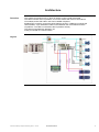
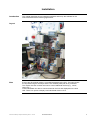
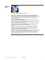
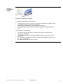
Premium and Advantys
TeSysU and Phaseo
System User Guide
33003546.02
[source code]
Contents
Application example – Source code......................................................................................2
Typical applications................................................................................................................3
Architecture.............................................................................................................................4
Installation...............................................................................................................................6
Hardware .............................................................................................................................................................7
Software ............................................................................................................................................................12
Communication .................................................................................................................................................13
Implementation .....................................................................................................................18
TeSysU..............................................................................................................................................................20
Advantys............................................................................................................................................................21
PLC....................................................................................................................................................................30
HMI ....................................................................................................................................................................39
Addendum .............................................................................................................................46
Detailed components list.......................................................................................................46
Component Features ............................................................................................................47
Contact ..................................................................................................................................55
Introduction
This document is intended to provide a quick introduction to the described System.
It is not intended to replace any specific product documentation. On the contrary, it offers
additional information to the product documentation, for installing, configuring and starting up the
system.
A detailed functional description or the specification for a specific user application is not part of
this document. Nevertheless, the document outlines some typical applications where the system
might be implemented.
Premium and Advantys TeSysU and Phaseo_EN.doc – Juni-05
Schneider Electric
1
Abbreviations
Word/Expression
PLC
HMI
PC
AC
DC
PSU
I/O
VSD (VVD)
Premium
Unity (Pro)
Magelis
Phaseo
TeSys U
Explanation
Programmable Logic Controller
Human Machine Interface
Personal Computer
Alternating Current
Direct Current
Power Supply Unit
Input/Output
Variable Speed Drive (Variable Velocity Drive)
Name of a Schneider Electric PLC
Name of Schneider Electric PLC programming software
Name of Schneider Electric Human Machine Interface
Name of a Schneider Electric range of power supply units
Name of a Schneider Electric distributed I/O system (Small
Terminal Block)
Application example – Source code
Introduction
Examples of the source code used to attain the system function as described in this document
can be downloaded from our „Village“ website under this link.
Premium and Advantys TeSysU and Phaseo_EN.doc – Juni-05
Schneider Electric
2
Typical applications
Introduction
Application
The following chapter describes some typical applications or partial applications for
this system.
Description
Example
Motor control
Used for starting and protecting pumps.
Material
conveyors
Used for starting up and controlling the
conveyors in packaging machinery.
Water
management
Used for controlling and monitoring
water pumps in water treatment plants.
Premium and Advantys TeSysU and Phaseo_EN.doc – Juni-05
Schneider Electric
3
Architecture
Overview
The system concerned is a PLC, which is used to control a local drive island.
The island consists of an I/O platform, four motor starters with motors, two external
I/O modules, and a HMI. Other units can be added if required.
Modbus/TCP is used to connect the drive island to the PLC. CANopen is used as the
island fieldbus. A pre-assembled cable is used between the motor starters and the
I/O platform. The HMI is connected to the I/O platform directly.
The island is supplied with 400/230 V AC.
Safety is ensured via a master switch.
Layout
Premium and Advantys TeSysU and Phaseo_EN.doc – Juni-05
Schneider Electric
4
Components
Hardware:
• TSX Premium (PLC)
•
Phaseo (power supply)
•
TeSysU (motor starter, 4x)
•
Magelis XBTN (HMI)
•
Advantys STB (remote I/O)
•
Advantys FTB (I/O module IP 67)
•
AC motor (4x)
Software:
• Unity Pro 2.0.2 (PLC)
Dimensions
•
Advantys configuration software 1.90 (remote I/O)
•
XBT-L1000 4.3 (HMI)
The compact size of the individual IP20 drive island components means that it is
possible to house them in a control cabinet with the following approximate external
dimensions: 500 x 300 x 200 mm (WxHxD). The XBTN and the master switch can be
installed in the front door for operation there.
Premium and Advantys TeSysU and Phaseo_EN.doc – Juni-05
Schneider Electric
5
Installation
Introduction
This chapter describes how to install the hardware and set up the software for the
task associated with the following applications:
Layout
Note
Each of the drive island motors is controlled separately by the PLC. The input signals
are imported using the Advantys and the I/O modules (FTB) with IP 67 protection.
The outputs of these modules are used to control additional devices (e.g., valves,
lamps, etc.).
Cross-island data can also be communicated to the PLC and displayed on the local
HMI. There is an option to display local island data without a PLC.
Premium and Advantys TeSysU and Phaseo_EN.doc – Juni-05
Schneider Electric
6
Hardware
General
Components
•
For assembly purposes, the power supply and Advantys STB require a top-hat rail.
•
The motor starters can either be attached to a top-hat rail or to the mounting plate
directly.
•
The other devices can be attached directly to the mounting plate.
•
400/230 V AC cables connect the master switch, power supply, PLC and motor
starter.
•
The 24 V DC cable is used between the power supply, HMI, Advantys STB and FTB.
Master switch
VCF-02GE
Power supply
ABL7RE2403
Continued on next page
Premium and Advantys TeSysU and Phaseo_EN.doc – Juni-05
Schneider Electric
7
Components,
continued
Premium PLC
TSX
TSX P57 5634M
1
2
3
5
6
8
9
10
Display LEDs
Eject button for
PCMCIA SRAM card
Terminal port
(TER)
Slot for a memory expansion card
(PCMCIA)
Slot for a communication card
(PCMCIA)
RJ45 connector for Ethernet
connection
USB port
RESET button
Premium power
supply
TSX PSY 5500
Continued on next page
Premium and Advantys TeSysU and Phaseo_EN.doc – Juni-05
Schneider Electric
8
Components,
continued
TeSysU
motor starter
LUB12
LUCB05BL
LUFC00
LU9BN11N
The powerrelated
components are
oriented by the
motor used.
Motor
•
•
Type: AC motor
Size: Application-specific
The power must be compatible with the TeSysU motor starter
triggering unit.
Magelis HMI
XBT-N401
1
2
3
4
Front face
SubD25 serial interface
3-wire terminal for 24 V DC supply
MiniDIN printer connection (to be used later)
Continued on next page
Premium and Advantys TeSysU and Phaseo_EN.doc – Juni-05
Schneider Electric
9
Components,
Advantys STB
continued
Advantys STB
Ethernet bus
adapter
STB NIP 2212
Field power
supply
STB PDT 3100
Note:
The output power
supply can be
deactivated
independently of
the inputs (e.g., in
case of an
emergency off).
Continued on next page
Premium and Advantys TeSysU and Phaseo_EN.doc – Juni-05
Schneider Electric
10
Advantys FTB
FTB 1CN12E04
FTB 1CN08E08
Advantys FTB
Power supply
and bus
connection
Note:
For the assignment of the sensor inputs and actuator outputs,
please refer to the product description of the module concerned.
Premium and Advantys TeSysU and Phaseo_EN.doc – Juni-05
Schneider Electric
11
Software
General
You will need to install the Unity Pro programming software for the Premium PLC,
the Advantys configuration software for the Advantys STB with CANopen extension
and the XBTL1000 software for creating visualization.
A Microsoft Windows® operating system must be installed on the PC:
•
•
Windows® 2000 or
Windows® XP
Premium and Advantys TeSysU and Phaseo_EN.doc – Juni-05
Schneider Electric
12
Communication
General
The methods of communication below are used between devices:
• CANopen
• Modbus/TCP
• Modbus
• Parallel cabling
CANopen is used as an extension to facilitate communication between the Advantys
STB and the fieldbus devices (Advantys FTB).
Modbus/TCP is used for communication between Advantys STB and the PLC. The
Ethernet cable is used either for the connection via a hub or switch or for a direct
connection with a crossed Ethernet cable.
Modbus is used between Advantys STB and the HMI.
Parallel cabling uses a pre-assembled cable to connect the I/O island to the motor
starter. This rules out the possibility of cabling errors.
Premium PLC
TSX P57
5634M
1 - Serial link between PC
with Unity Pro and PLC
(TER/AUX), using cable TSX
PCX 1031 (switch position
“0”)
2 - Alternative connection
between USB interface on
the PC (with Unity Pro) and
the PLC, using connection
cable
UNY XCA USB 033
3 - The Ethernet interface is
used for the IO scanner and
other PLC services. It can
also be used as a
programming interface (Unity
Pro). A switch or hub and an
Ethernet cable are required
to establish an Ethernet
connection.
HMI
Connection cable
XBT Z915:
Used for programming the
HMI (XBTN) via the serial
interface on the PC, with
HMI software (XBTL).
Premium and Advantys TeSysU and Phaseo_EN.doc – Juni-05
Schneider Electric
13
Advantys STB
HMI data cable
XBT Z988:
The XBTZ988 data cable is
required to connect the local
HMI (D-sub, 25-pin) to the
Advantys (CFG port).
Therefore, the distributed I/O
data on the fieldbus island
can be visualized on site
directly, without a PLC. Data
can also be exchanged
between the HMI device and
the PLC via the so-called
HMI/PLC data area.
Ethernet connection
STB NIP 2212
1
2
3
4
5
6
7
8
9
Ethernet interface
MAC ID
Top rotary switch
Bottom rotary switch
Space to enter the IP address
Power supply interface
LED area
Card slot for the removable memory card
Cover for CFG port
The two NIM rotary switches (3/4) can be used to define
how an IP address is assigned. There are two options:
a) Allocation via a central address server (e.g., in the
PLC). The MAC address (BOOTP) or “ROLE
NAME” is used for identification.
b) The internal IP address (INTERNAL) is used.
Continued on next page
Premium and Advantys TeSysU and Phaseo_EN.doc – Juni-05
Schneider Electric
14
Advantys STB,
continued
Connection with the
configuration software:
An STB XCA 4002
programming cable is used
for the connection for
programming the Advantys
via the serial interface on the
PC (with Advantys software).
Alternatively, the connection
can be made via Ethernet.
CANopen expansion card
STB XBE 2100
Premium and Advantys TeSysU and Phaseo_EN.doc – Juni-05
Schneider Electric
15
Advantys FTB
CANopen bus connection
cable
FTX CN32xx
Note:
xx stands for varying lengths.
The FTXCN3210 cable is
used for the connection.
Provided that two FTBs are
directly connected to one
another, the cables can be
used as they are.
Note: If, on the other hand, a
connection is made to the
ATV junction box or
Advantys STB, one of the
connectors must be removed
and the cables attached
separately.
CANopen bus termination
FTX CNTL12
Power supply cable
FTX DP22xx
Note:
xx stands for varying lengths.
Premium and Advantys TeSysU and Phaseo_EN.doc – Juni-05
Schneider Electric
16
TeSys U
Advantys connection cable
LU9R10
Used to connect the
Advantys STB EPI2145
module.
1
2
3
Advantys module STB EPI2145 *)
Communication module LUF C00
connection)
Connection cable LU9R10
(parallel
*) The STB EPI 2145 is an Advantys STB special
module that establishes parallel cabling between an
Advantys STB and up to four reversible TeSys U units.
Each of the four channels on the STB EPI 2145
comprises two outputs (start forwards and start
backwards) and three inputs (ready for operation, run
message and error status).
This combination precludes cabling errors.
Premium and Advantys TeSysU and Phaseo_EN.doc – Juni-05
Schneider Electric
17
Implementation
Introduction
This chapter describes how to initialize, parameterize, program, and start up the
system.
Function
Functional description
1. For the purpose of operation, the PLC must be started and there must be an
Ethernet connection to the drive island, i.e., the Advantys STB.
2. As soon as the power is switched on, the drive island devices enter the
initialization phase. The IP address is taken from the PLC address server and
the CANopen extension is started.
3. The entire island is controlled via this PLC. For this purpose, the STB and FTB
input and output values are transferred between Advantys STB and the PLC.
Data is also exchanged between the HMI and the PLC via Advantys. Drive island
data can still be displayed without a PLC.
Layout
Premium and Advantys TeSysU and Phaseo_EN.doc – Juni-05
Schneider Electric
18
Order of tasks
Proceed as follows to optimize the setup time of the individual products:
1. Set up the TeSysU motor starters
2. Configure the I/O platform (module assembly, parameterization, etc.) using
Advantys Config Tool
3. Set communication parameters on Advantys STB and FTB
4. Create application program using Unity Pro
5. Parameterize Advantys STB online
6. Configure visualization (HMI) using XBT L1000 software
Proceeding in the sequence described above will ensure that the relevant
information can either be imported directly or entered manually from the previous
action.
Premium and Advantys TeSysU and Phaseo_EN.doc – Juni-05
Schneider Electric
19
TeSysU
Introduction
This chapter presents the motor starter components used in this system. They can be
adapted according to the application (motor output, reversing or non-reversing drive).
Basically, the TeSys U motor control unit comprises:
•
•
•
•
•
Power base
Control unit
Communication module
Coil wiring kit
Optional: reversing block, Is limiter/isolation block and other modules
TeSysU
Power base
LUB12
Control unit
LUCB 05 BL
1
LUF C00 – communication module with parallel wiring
2
LU9B N11C – coil wiring kit
Note
The LUF C00 module with parallel wiring enables motor controls to be connected to the
I/O modules of PLCs quickly and without the need for tools. It replaces conventional
systems using a screw terminal block and single-conductor wiring. The module with
parallel wiring collects all information regarding the states and control commands of
each motor control. The connection module distributes information from the PLC I/O
modules to each connected motor control.
Note
The following points should be taken into account when selecting components:
1. A 24 V DC LUCx xx BL control unit must be used. The BL extension should be
observed.
2. There are different versions of the coil wiring kit, which depend on the power base.
LU9B N11C should be used if the power base has one direction of rotation (LUBxx)
and LU9M RC should be used if the power base has two directions of rotation
(LU2Bxx).
Premium and Advantys TeSysU and Phaseo_EN.doc – Juni-05
Schneider Electric
20
Advantys
Introduction
This chapter describes how to configure the I/O platform. The Advantys configuration
software is used for this purpose.
Proceed as follows:
1. Create a new project (workspace)
2. Configure the hardware (network interface, power supply and I/O modules)
3. Configure CANopen extension communication (baud rate)
4. Adjust device parameters (reset inputs, settings, etc.)
5. Download the configuration to the Advantys STB
General
The address and transfer rate must be specified for all the devices on the CANopen
extension. It is important to ensure that the addresses run consecutively in descending
order, starting with 32, which is the maximum start address. The maximum start address
can be adjusted between 8 and 32 using the Advantys software (see “Advantys STB –
Specifying address and transfer rate").
Creating a
new project
1
After starting the Advantys
software, you must create a
new workspace.
2
To do this, you must specify the
path, the workspace name and
the name of the first island.
Premium and Advantys TeSysU and Phaseo_EN.doc – Juni-05
Schneider Electric
21
Configuring
the hardware
1
The STB NIP 2212 Ethernet
network interface is selected in
the catalog under "Network" as
the starting module.
2
Double-click on this module to
open the Parameters view.
The maximum address of the
CANopen extension (32 in this
example) can be adjusted here.
The number of registers (every
five words in this example) to
be exchanged between the PLC
and HMI via the Advantys
module can also be specified.
3
Result:
Premium and Advantys TeSysU and Phaseo_EN.doc – Juni-05
Schneider Electric
22
Configuring
the hardware
continued
4
5
The content of blocks 1, 2, 7,
and 8 can be read and written
to block 9 using the HMI.
Agreed data is exchanged with
the PLC (fieldbus master) via
blocks 2 and 9.
Output data process image
(4096 registers available)
Block 2
Output table for
fieldbus master to HMI
(512 registers available)
Block 7
35 predefined island bus
status registers
Block 8
Input data/status
process image
(4096 registers available)
Block 9
Input table for HMI to
fieldbus master
(512 registers available)
Next, add the other modules
from the catalog:
•
•
•
•
•
•
6
Block 1
STB PDT 3100
Field power supply
STB DDI3610
6 digital inputs
STB DRC 3210
2 relay outputs
STB EPI 2145
Parallel interface
STB XPE 2100
CANopen extension
(must be the last one)
STB XMP 1100
Bus termination
Finally, the CANopen extension
is configured by selecting the
devices in the catalog under
“Extended CANopen”. These
are:
•
•
FTB 1CN 12E04SP0
12 inputs/4 outputs
FTB 1CN 08E08SP0
8 inputs/8 outputs
Addressing on the extension is
performed automatically in
accordance with the sequence
on the bus. If specific
addresses are required, the
devices should be moved or the
maximum start address should
be changed.
Premium and Advantys TeSysU and Phaseo_EN.doc – Juni-05
Schneider Electric
23
Configuring
CANopen
communication
1
Baud rate
The baud rate can be set via
the menu bar. In this example
the rate used is 500 kbps.
The baud rate depends on the
modules used how they are
distributed. The CANopen
specification should be
observed.
Adjusting the
device
parameters
1
It is possible to specify parameters for the individual devices on the CANopen
extension, which are transferred to the devices every time the bus is restarted.
2
Double-click on the device to
open the Parameters window.
The setting for the FTB devices
is shown here, for example. The
entry is made in the “Value”
field.
Note on FTB-Device:
Normally the diagnostic
parameters of the separate
channels are activated (value
1). In order to use Pin2 as
optional input, the value must
be set to 0. In the example
channels 1-8 are set to 0.
Premium and Advantys TeSysU and Phaseo_EN.doc – Juni-05
Schneider Electric
24
I/O assignment
1
You can use the "I/O Image
Overview ..." menu item
(located in the “Island” menu) or
the equivalent icon to call the
function for assigning the I/O to
the memory areas.
2
The information concerning the
selected data is displayed in the
description field. Alternatively,
the project can also be printed
out. The printout will contain the
same information.
Inputs
• Advantys STB/FTB
from 45392
to 45411
20 words
•
PLC -> HMI
from 49488
to 49492
5 words
Outputs
• Advantys STB/FTB
from 40001
to 40004
4 words
•
HMI -> PLC
from 44097
to 44101
5 words
Premium and Advantys TeSysU and Phaseo_EN.doc – Juni-05
Schneider Electric
25
Downloading
the
configuration
1
Start by selecting the “Build”
option in the “Island” menu
or the equivalent icon to
generate a machine-readable
version from the completed
configuration.
2
An information window will be
displayed while the build is in
progress. Once the build
process is complete, a
message will be displayed
informing you of whether or
not the operation was
successful.
3
If this is the first time that a
connection to the island has
been established, start by
specifying the connection
settings. This is done by
selecting “Connection
Settings” from the “Online”
menu. In the case of a serial
link, the settings must be
made as per the screenshot
shown here and must be
compatible with the island.
Alternatively, if an IP address
already exists, a connection
via TCP/IP can be
parameterized.
Premium and Advantys TeSysU and Phaseo_EN.doc – Juni-05
Schneider Electric
26
Downloading
the
configuration,
continued
4
You can now establish a
connection to the island by
selecting "Connect" from the
"Online" menu or by pressing
the equivalent button.
Note: If no build operation has
yet been performed, the
software will now initiate an
automatic build.
5
Once the connection has been
established, the Advantys
software will detect that the
machine-readable version
generated does not match the
current configuration in the
island and will present you
with an option to “Download”
or “Upload”. After selecting
“Download”, confirm the
security prompt.
6
A progress bar will be
displayed during download.
Once the download is
complete, the island will
perform a reset and the
connection will be interrupted.
Once you have confirmed the
prompt, re-establish the
connection with the island.
Continued on next page
Premium and Advantys TeSysU and Phaseo_EN.doc – Juni-05
Schneider Electric
27
Downloading
the
configuration,
continued
Advantys STB
Specifying the
IP address
7
Once the connection has been
re-established, you can start
the island by selecting “Run”
from the “Online” menu or
pressing the equivalent button.
8
Confirm the prompt. Following
successful startup, the
following message will appear
in the output window: “No
errors. Island fully
operational.”
The type of IP address assignment is set via the rotary switches on the NIP 2212 island
head. Each of the rotary switch positions that can be used to specify a valid IP address
is indicated on the housing of the STB NIP 2212. There are a total of four different
methods for assigning addresses:
1.
2.
3.
4.
Assignment of the address via BOOTP
Assignment via DHCP
Assignment of a fixed IP address via the NIP 2212 Web page
Conversion of MAC address into an IP address
Within the context of the
example project, the address is
assigned using the BOOTP
mechanism, as the PLC’s
Ethernet interface has a
BOOTP server, making this the
simplest method. To use the
BOOTP method, you must set
the top rotary switch to the 0
position and the bottom one to
“BOOTP”.
Premium and Advantys TeSysU and Phaseo_EN.doc – Juni-05
Schneider Electric
28
Advantys FTB
Specifying the
address and
transfer rate
The CANopen address and transfer rate are set manually on the modules via rotary
switches. There are two rotary switches for the address and one for the transfer rate. In
the example software, both FTB modules are configured with the addresses 31 and 32
and the transfer rate is set to 500.0 kbps.
Element
1
Function
Transfer rate
2
Address 10x
3
Address 1x
Rotary switch position
0
1
2
3
4
5
6
7
8
9
Premium and Advantys TeSysU and Phaseo_EN.doc – Juni-05
Transfer rate
Autom. recognition
10 kbps
20 kbps
50 kbps
100 kbps
125 kbps
250 kbps
500 kbps
800 kbps
1 Mbps
Schneider Electric
29
PLC
Introduction
This chapter describes how to create a PLC program, including the logic for the drive
island, using the Unity Pro software.
Proceed as follows to integrate the PLC:
1. Create new project and select hardware
2. Configure Ethernet communication
3. Create application program (logic)
4. Connect PLC and download program
Creating a
new project
1
After starting Unity, the first
thing you need to do is create
a new project. When doing so,
you must select the correct
PLC.
2
Next, you should modify the
position of the CPU by
dragging and dropping and
insert the correct power
supply. Now save the project.
Continued on next page
Premium and Advantys TeSysU and Phaseo_EN.doc – Juni-05
Schneider Electric
30
Creating a new
project,
continued
3
Adjust the number of I/O data
items.
The peak values are used in
this example.
Configuring
Ethernet
communication
1
First, select “New Network”
under “Communication Network” in the project
browser.
2
In the “Add Network” window,
specify “Ethernet” as the
network type and enter a
name for the network under
"Change Name". Click OK to
create the network.
Continued on next page
Premium and Advantys TeSysU and Phaseo_EN.doc – Juni-05
Schneider Electric
31
Configuring
Ethernet
communication,
continued
3
Open the network and make
the following settings in the
sequence described:
• Select the model family
(expanded connection).
The tool tips show the
devices that belong to
each model family.
• Specify the IP address
and subnetwork mask.
• Activate the address
server and I/O scanning.
4
Next, click on the “Address
Server” tab and enter the MAC
address of the Advantys STB
island, along with the desired
IP address. On the NIP 2212,
you will find the MAC address
of the island printed
underneath the Ethernet port.
5
Overview:
6
You now need to configure I/O scanning
for the Advantys Island. To do this, click
on the “IO Scanning” tab and enter the
data below relating to the island's IP
address.
Continued on next page
Premium and Advantys TeSysU and Phaseo_EN.doc – Juni-05
Schneider Electric
32
Configuring
Ethernet
communication,
Continued
Column name
Health Timeout
[ms]
Repetitive rate
[ms]
RD Master Object
No. 1
1500
No. 2
1500
No. 3
1500
10
10
10
1000
1020
1025
RD Slave Index
5391
9487
5356
RD length
20
5
35
WR Master Object
2000
2004
0
WR Slave Index
0
4096
0
WR length
4
5
0
Description
Time-out for a fault
in ms
Data exchange repetition rate
in ms
Target for read data
in %MW
Start address for reading data from
island
corresponds to 4xxxx
Length of the read area
in words
Target for write data
in %MW
Start address for writing data to
island; corresponds to 4xxxx
Length of the write area
in words
Note:
The length of the read and write areas are based on the island’s I/O data image.
Regarding the island, the entered start addresses must be reduced by one in Unity.
Three configuration sequences are used. Area no. 3 can be combined with area no. 1.
However, to achieve greater clarity this was not carried out in this example.
The progression of a signal from the HMI to Advantys and on to the PLC and back is
shown here as an example:
Continued on next page
Premium and Advantys TeSysU and Phaseo_EN.doc – Juni-05
Schneider Electric
33
Configuring
Ethernet
communication,
continued
7
Now close the configuration and confirm acceptance of the changes when the
prompt appears.
8
The configured network must
be assigned to the hardware.
To do this, switch to the
Hardware view and doubleclick on the CPU network
connection. The window
opposite appears.
9
The following three settings
should be made and then
applied:
1. Select the channel (in this
example, channel 3)
2. Select the function (in this
example, ETH_TCP_IP)
3. Select the network
connection (the configured
connection)
In Unity, an existing structure can be used to monitor the Ethernet interface.
To do this, specify a variable name in the data editor and assign
E_COM_ETHCOPRO as the type. Also, the Ethernet interface address is entered
as the address. This is “%CH0.1.3” in this example. The content of the structure
can be looked up in Unity online help.
Premium and Advantys TeSysU and Phaseo_EN.doc – Juni-05
Schneider Electric
34
Creating the
application
program
1
First, you need to declare
variables and assign them to
input and output data of the
drive island, assuming that
you do not intend to make use
of direct addresses.
Individual variables have been
used for the inputs and
outputs in the example
program.
2
The application program is
now programmed, and
depends on the requirements
of the machine or process.
3
A graphical interface and
animation tables can then be
created to be used for startup.
Note:
The creation of
the application
program is only
described here
in a general
sense.
Premium and Advantys TeSysU and Phaseo_EN.doc – Juni-05
Schneider Electric
35
Downloading
a program
1
Upon completion of
programming, the entire
project must be built. To do
this, select the relevant menu
item or button.
2
Depending on the connection
used, you can select
UNTLW01 for a Uni-Telway
connection or USB for a USB
connection. In both cases, the
PLC SYS address should be
used as the standard system
address.
A connection can also be
created via TCP/IP if a
program with an IP address is
already running.
3
The connection is made using
the "Connect" menu item from
the "PLC" menu, or the
equivalent button. The
programming cable (serial,
USB or Ethernet) must be
connected to the PLC.
Transfer the application
program to the PLC and then
start the PLC.
4
Note: If you want the PLC to
start as soon as the download
is complete, you must check
the relevant box before
starting the transfer.
Premium and Advantys TeSysU and Phaseo_EN.doc – Juni-05
Schneider Electric
36
Parameterizing
Advantys STB
online
1
When the application program
is running in the PLC, the
BOOTP server is also active.
Following an Advantys STB
Power Cycle, the IP address is
transferred and the island can
be reached using this address
and a Web browser.
The default login is USER and
the password is also USER.
The password can be changed
in the Security area.
2
The master configurator and
the master controller can both
be accessed in the
Configuration area.
3
The following settings should
be made in order to use an
HMI on the CFG port:
Master Controller
Reservation Time:
0
Continued on next page
Premium and Advantys TeSysU and Phaseo_EN.doc – Juni-05
Schneider Electric
37
Parameterizing
Advantys STB
online,
continued
4
Master Configurator
Master:
Serial
Reservation Time:
0
All of the settings should be
saved.
Premium and Advantys TeSysU and Phaseo_EN.doc – Juni-05
Schneider Electric
38
HMI
Introduction
This section describes how to set up the Magelis HMI’s visual display. The HMI
application for the XBT N401 is created using the XBT-L1000 HMI software.
Proceed as follows to integrate the HMI:
1. Create a new project
2. Configure the HMI
3. Create an application page
4. Simulate the application
5. Transfer to the operator terminal
Creating a new
project
1
Create a new project
Configuring the
HMI
1
Select the terminal type:
•
•
2
Type:
Protocol:
XBT N401
Modbus
In the same dialog, select the
Modbus communication
protocol parameters.
Premium and Advantys TeSysU and Phaseo_EN.doc – Juni-05
Schneider Electric
39
Modbus
protocol
parameters
1
Set the Modbus protocol
parameters.
The same parameters as
those on the Advantys STB
CFG port should be set.
These are:
2
Creating basic
parameters
• Speed: 9600 bauds
• Parity:
Even
Click “OK” to close this
window and continue with the
parameterization by clicking
“Next”.
1
Assign project name
and click “Next”.
2
Enter the symbolic names and
the network address for the
connected devices in this
window.
The network address must
match that of the Advantys
STB CFG port.
3
Continue by setting the
language.
Continued on next page
Premium and Advantys TeSysU and Phaseo_EN.doc – Juni-05
Schneider Electric
40
Creating basic
parameters,
continued
4
Do not make settings for the
terminal and dialogue table.
Creating text
objects
1
After completing the basic
parameters, create the
application pages.
2
Text objects and links to other
pages can be created on an
application page.
Properties can be assigned to
the alphanumeric fields.
First, specify the variable,
which is to activate the field.
Continued on next page
Premium and Advantys TeSysU and Phaseo_EN.doc – Juni-05
Schneider Electric
41
Creating text
objects,
continued
3
Select the source/target from
the “Equipment” drop-down
list. Enter Advantys here.
On the first screen, bit 8 of
word %MW9488 is used.
On the second screen, the
whole word %MW4099 is
used.
4
Different formats are available
for the display. The first or
second text is displayed here,
depending on the bit state.
As well as the text, which has
been converted from a value,
the value itself can also be
displayed.
5
The tab also indicates whether
the variable is read-only, writeonly or read/write.
Premium and Advantys TeSysU and Phaseo_EN.doc – Juni-05
Schneider Electric
42
Simulating the
application
1
The application can be
simulated “offline” (without
HMI connected)
using the simulation function
of the XBT-L1003 software.
Transfer to the
operator
terminal
1
In order to download the application from the PC to the Magelis
XBT-N401, you will need to connect the XBT-Z915 communication
cable.
Select the menu item:
Transfers Æ Export Æ
To Terminal
2
Display pages
3
After a short delay, a popup
menu will appear asking
whether you wish to continue
with the download.
1
The “Page Tree” window
contains information about the
display pages and their
connections.
Continued on next page
Premium and Advantys TeSysU and Phaseo_EN.doc – Juni-05
Schneider Electric
43
Display pages,
continued
2
From the individual pages,
other pages that have to be
configured accordingly can be
called.
3
The configured pages are
shown below.
AUTO or MANU mode can be
selected on the start page.
From here, you can switch to
the other pages.
4
The three state indications for
the first two TeSysU motor
controls are shown here. The
drive can also be switched on
and off (in Manu-Mode).
5
As above for numbers 3 and 4
only.
Continued on next page
Premium and Advantys TeSysU and Phaseo_EN.doc – Juni-05
Schneider Electric
44
Display pages,
continued
6
All of the drive's run messages
are shown on this page, as is
the PLC’s value in seconds.
Premium and Advantys TeSysU and Phaseo_EN.doc – Juni-05
Schneider Electric
45
Addendum
Detailed components list
Type/software
Description
ABL7RE2403
POWER SUPPLY 240 V AC 1PH 24 V DC 3 A
VCF02GE
EMERGENCY OFF MASTER SWITCH
TSXP575634M
Premium CPU; 640 KB INTEGR.ETH
TSXPSY5500M
115/230 V AC/55 W power supply
TSXRKY8EX
Expandable backplane 8
TSXTLYEX
Terminating resistors A and B
TSXPCX1031
Communication cable multifunctional
UNYXCAUSB033
Communication cable USB (optional)
STBPDT3100
POWER SUPPLY 24 V DC PDM STAND.
STB NIP 2212
BUS COUPLER ETHERNET NIM STAND.
STB XCA 4002
CONFIGURATION CABLE RS232 SUBD/HE13 2M
STB XBE 2100
CANopen extension module
STBXBA3000
BASE I/O TYPE3 27 MM
STBXBA2200
BASE PDM 18 MM
STBDRC3210
MODULE 2 OUT RELAY C 24 V DC/2 A
STBDDI3610
MODULE 6 IN 24 V DC SINK 2-WIRE 0.1 MS FIX. S
STBXMP1100
BUS TERMINATOR MODULE ISLAND BUS
STBXTS2100
CONNECTOR I/O 6 CONN. CAGE CLAMP TERM. (20)
STBXBA1000
BASE I/O TYPE1 13.5 MM
STBXBA2000
BASE I/O TYPE2 18 MM
STBXTS1100
CONNECTOR I/O 6 SCREW-TYPE TERM. CONN. (20)
STBXTS1110
CONNECTOR I/O 5 SCREW-TYPE TERM. CONN. (20)
STBXTS1120
CONNECTOR NIM 2 SCREW-TYPE TERM. CONN. (10)
STBXTS1130
CONNECTOR PDM 2 SCREW-TYPE TERM. CONN
XBT N401
HMI
XBT Z988
HMI cable to Advantys STB
XBT Z915
Programming cable
FTB1CN12E04SP0
DIGITAL I/O 24 V DC 12 IN 04 OUT IP 67 CANopen bus
FTB1CN08E08SP0
DIGITAL I/O 24 V DC 08 IN 08 OUT IP 67 CANopen bus
FTXDP22xx
Power supply cable (xx stands for length)
FTXCN32xx
FTX CNTL12
Connection cable for connecting FTB to CANopen bus
(xx stands for length)
CANopen bus termination
LUB12
TeSysU power base
LUCB05BL
Control unit
LUFC00
Communication module with parallel wiring
LU9BN11N
Coil wiring kit
LU9R10
Connection cable for connecting TeSysU to STB
UNYSPUEFUCD20
Unity Pro XL single-user license
V2.0.2
STBSPU1000
ADVANTYS software incl. RS232 cable
V1.9
XBTL1000
HMI software
V4.3
Premium and Advantys TeSysU and Phaseo_EN.doc – Juni-05
Schneider Electric
Rev./version
46
Component Features
Premium PLC
Premium PLC TSX P57 5634M
I/O capacity:
2040 digital I/Os
512 analog I/Os
64 intelligent channels
Data register:
640 KB integrated
Max. 7168 KB via PCMCIA
Controller channels:
30
Max. number of bus/
network interfaces:
4 networks
8 AS-Interface
1 CANopen bus (via PCMCIA)
5 fieldbuses (INTERBUS or Profibus DP)
Integrated interface:
Ethernet TCP/IP
Programming:
Unity Pro
Phaseo power
supply
Phaseo power supply ABL7RE2403
Input voltage:
100 to 240 V ~, single-phase, 50/60 Hz
Output voltage:
24 V =
Output current:
3.0 A (up to 10 A with ABL7RE2410)
Premium and Advantys TeSysU and Phaseo_EN.doc – Juni-05
Schneider Electric
47
Advantys STB
Advantys STB
•
•
•
•
•
•
Modular I/O system with
• Various fieldbus couplers
• Analog and digital modules
• Counter
• Expert modules
I/O selectivity 2 to 16 channels
Open to motor starters, variable speed drives/drives and devices from third-party
manufacturers thanks to the bus backplane
Product dimensions
• General:
120 x 78 mm (HxD)
• Fieldbus coupler:
40.5 mm wide
• I/Os and power module: 13.5 or 18 mm wide
Advantys STB has 7 different fieldbus interfaces, also called NIM
• CANopen
• Ethernet TCP/IP
• DeviceNet
• Modbus Plus
• INTERBUS
• FIPIO
• Profibus DP
Other features
• Removable memory card
• I/O modules modified and parameterized via the serial interface
• Local HMI can be connected via the serial interface
• Direct, on site open-loop and closed-loop control, even if communication with
the PLC fails
• HotSwap
• Separate infeed for input and output voltage
• Detailed diagnostics
• Reflex functions (intelligent preprocessing)
Premium and Advantys TeSysU and Phaseo_EN.doc – Juni-05
Schneider Electric
48
Advantys FTB
(Field Terminal
Block)
Advantys FTB
•
•
•
•
•
•
•
•
•
Block modules for
• 16 digital inputs
• 8 digital inputs/8 digital outputs
• Digital inputs/4 digital outputs
• 16 configurable digital inputs/outputs
Protection class: IP 65/67
Plastic or metal housing
Various fieldbus interfaces
•
Profibus
•
CANopen
•
Interbus
•
DeviceNet
Diagnostic capability via LED
•
Module diagnostics (bus and voltage monitoring)
•
Channel diagnostics (open circuit, overcurrent, etc.)
Module and channel diagnostics sent to the PLC via the fieldbus
Module features
•
Short-circuit-proof and undervoltage monitoring
•
Reverse voltage protection
•
Inputs and outputs electrically isolated from the fieldbus
Input features
•
Input characteristic according to IEC 1131-2 Type 2
•
Current consumption max. 200 mA per input
•
Reverse voltage protection
Output features
•
Protection against overvoltage
•
1.6 A per output
Premium and Advantys TeSysU and Phaseo_EN.doc – Juni-05
Schneider Electric
49
TeSys model U
TeSys model U
•
•
•
•
•
•
One power base
Control unit 0.15 to 32 A
• Only 6 setting ranges up to 32 A
• Only 4 voltage ranges up to 240 V AC/DC
• 3 versions: Standard, Extended, Multifunctional
Overall width 45 mm
Complete reversing contactor combination 0.15 to 32 A
Auxiliary switches and function modules
• Integrated: Motor circuit breaker auxiliary contact 1 NC, with connectors
• Integrated: Contactor auxiliary contacts 1 NO + 1 NC, freely available
• Option: Auxiliary switch module with 2 contactor state contacts
• Option: Signal contact “Error” and “Selector switch position”
• Function module alarm – thermal overload
• Function module – motor load display (0 to 10 V, 4 to 20 mA)
• Function module – differentiated error display (under development)
Communication modules
• Parallel wiring; with plug-in connection cables up to eight motor controls can
be supplied on one distribution module
• AS-i, profile V2 (V2.1 under development)
• Modbus RTU protocol
• Gateway: FIPIO/Modbus, DeviceNet/Modbus, Profibus DP/Modbus
Premium and Advantys TeSysU and Phaseo_EN.doc – Juni-05
Schneider Electric
50
Magelis HMI
Magelis HMI XBT-N401
•
•
•
Display
• Reduced construction size for installation in compact machines
• Display front only 132 x 74 mm
• Depth only 31 mm (terminal)
• x 20 characters
• Characters displayed in large format
• Cyrillic characters
• 3-color backlight (green, orange, red)
Ergonomics
• 8 buttons, 4 of which are labeled
• Adapt according to requirements using removable labels
(cursor control/data modification, function key control and empty keypads)
• Simple navigation of the application pages
• 2 command buttons for each page
Environmental conditions
• Front face degree of protection:
IP 65 in accordance with IEC529,
NEMA 4X (outdoor)
• Rear face degree of protection:
IP 20 in accordance with IEC 529
• Operating temperature range 0 to 55ºC
• Operating humidity
0 to 85% (no condensation)
• Vibration rating in accordance with IEC 68-2-6, 10 to 50 Hz 0.075 mm, 57 to
150 Hz 1g
• Shock resistance in accordance with IEC 68-2-27, 11 ms, 15 g half-sine
shaped
Pulses in three axes
Premium and Advantys TeSysU and Phaseo_EN.doc – Juni-05
Schneider Electric
51
Unity Pro
programming
software
UNY SPU EFU CD 20 programming software
Unity Pro is the combined programming, testing and operating software for the
Premium, Atrium and Quantum PLCs. It uses all the proven standards from the PL7
and Concept software and provides a complete package with new functions for even
more productivity and openness when compared to other software programs.
Unity Pro supports all 5
IEC 61131-3 programming languages as standard with all test functions via PC
simulation or online on the PLC directly.
Thanks to the icon variables that are independent of the memory, the structured data
and the user function blocks, the application objects are mapped directly from the
special components of the automated process.
The user configures the Unity Pro operator screens within the application using the
graphical libraries. Operator access is simple and direct.
The test and maintenance functions are simplified thanks to animated graphic
objects.
For diagnosis, all system and application errors are displayed in plain text and in
chronological order (date and time is provided at the origin) in a visualization
window. You can return to the source of the conditions that have caused the error
using the navigation function for troubleshooting.
The XML format, a Web standard for data exchange, has been used as the source
format for Unity applications. The simple import/export functions mean that the entire
application or parts of it can be exchanged with other software in your project.
The converters integrated in Unity Pro automatically convert PL7 and Concept
programs into Unity Pro programs.
Premium and Advantys TeSysU and Phaseo_EN.doc – Juni-05
Schneider Electric
52
Advantys
configuration
software
Advantys configuration software
An Advantys STB system is configured by:
•
•
•
Parameterizing all the I/O modules on the Advantys STB platform (digital, analog
and intelligent modules) with standard functions.
Parameterizing the reflex functions executed at island level.
Setting these parameters using the Advantys configuration software STB SPU
1000.
This software can also be used:
•
•
•
•
To optimize island performance by specifying priorities to be applied when
processing module data
To add preferred modules or standard CANopen devices (such as FTB, OTB
and ATV31)
To check that the configuration complies with the design guidelines and to check
the current consumption
To change the module’s standard functions.
Premium and Advantys TeSysU and Phaseo_EN.doc – Juni-05
Schneider Electric
53
HMI software
XBT-L1003
The XBT-L1003 configuration software can be used to develop dialog applications
for all the HMIs in the Magelis range.
The XBT-L1003 software should run on any IBM-compatible PC with a Windows
operating system. The applications produced using the XBT-L1003 software are
independent of the protocol used; an operator dialog application can be used in
conjunction with any of the various PLCs that are available from leading market
suppliers.
It enables various types of page to be created with ease:
•
•
•
•
Application pages (can be linked to one another)
Alarm pages
Help pages
Form pages
The pages can contain variables and graphic objects of any type, which are either
predefined using the XBT-L1003 software or created by means of other applications
and then imported (bitmaps, etc.). They can have various properties assigned to
them: Min./max. limits, color, displacement, weighting, etc.
The XBT-L1003 software can be used to configure the function keys, via which
commands are to be issued for the machine or application pages are to be called.
Moreover, in the case of the graphic HMI, the PLC symbol databases can be
imported.
Premium and Advantys TeSysU and Phaseo_EN.doc – Juni-05
Schneider Electric
54
Contact
Author
Schneider Electric GmbH
Customer & Market
System & Architecture
Architecture Definition
Support
Schneider Electric GmbH
Steinheimer Strasse 117
D - 63500 Seligenstadt
Germany
Premium and Advantys TeSysU and Phaseo_EN.doc
Phone
E-mail
+49 6182 81 2555
[email protected]
As standards, specifications and designs
change from time to time, please ask for
confirmation of the information given in this
publication.
55