1
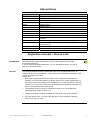
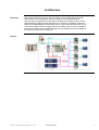
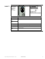
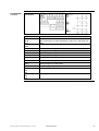
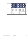
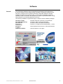
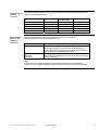
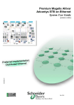
Premium and Advantys STB on Profibus DP
Advantys STB, FTB and Altivar on CANopen
System Manual Document
33003548.00
Including example source code
Contents
Application example – Source code......................................................................................2
Typical applications................................................................................................................3
Architecture.............................................................................................................................4
Installation...............................................................................................................................6
Hardware .............................................................................................................................................................7
Software ............................................................................................................................................................14
Communication .................................................................................................................................................15
Implementation .....................................................................................................................18
CANopen extension ..........................................................................................................................................20
ATV31 variable speed drive ..............................................................................................................................22
I/O platform........................................................................................................................................................25
Profibus .............................................................................................................................................................31
PLC....................................................................................................................................................................34
Operating behavior............................................................................................................................................39
Addendum .............................................................................................................................41
Detailed components list ...................................................................................................................................41
Introduction
This System Manual Document has been designed as a “quick start manual” for a system.
It is not meant as a substitute for any other product documentation.
Rather, it provides all the supplementary information required to install, parameterize and start
up the system concerned.
The functional description or specification of a specific user application is not within the scope of
this manual.
Nevertheless, the document outlines some typical applications in which the system can be
implemented.
Premium and Advantys STB on Profibus DP.doc – Juni-05
Schneider Electric
1
Abbreviations
Word/Expression
PLC
HMI
PC
V AC
V DC
PS
I/O
VSD (VVD)
Premium
Unity (Pro)
Sycon
Phaseo
Advantys STB
Advantys FTB
ATV31
Explanation
Programmable Logic Controller
Human Machine Interface
Personal Computer
Alternating Current
Direct Current
Power Supply
Input/Output
Variable Speed Drive (Variable Velocity Drive)
Name of a Schneider Electric PLC
Name of a piece of Schneider Electric PLC programming software
Name of a piece of Schneider Electric fieldbus programming
software
Name of a Schneider Electric range of power supply units
Name of a Schneider Electric distributed I/O system (Small
Terminal Block)
Name of Schneider Electric I/O modules
Name of a Schneider variable speed drive
Application example – Source code
Introduction
The attached files contain example source code, which represents the system
functionality described.
If you have Adobe Acrobat Reader V6.0, you can download the files to your PC by
clicking on the button below.
General
The example software includes a PowerSuite project for configuring the ATV31, an
Advantys project for the I/O platform, a Sycon project for the Profibus configuration, and
a Unity Pro project for the PLC.
Please note:
• Before the configuration data for the ATV31 can be used with the PowerSuite
software, it must first be imported. To do this, select ATV31 under Configurations in
the project tree and then load the four configurations one after the other by selecting
“Import” in the “File” menu. These are then subsequently assigned to the devices by
means of a separate process (see above).
•
The Advantys project is ready for immediate use with V1.2.0 of the Advantys
software and the update for the ATV31.
•
The Sycon project is ready for immediate use with V2.8 of the Sycon software.
•
The Unity project is an *.xef type import file, which can be opened by selecting
“Open” from the “File” menu.
Premium and Advantys STB on Profibus DP.doc – Juni-05
Schneider Electric
2
Typical applications
Introduction
Application
The following chapter describes some typical applications or partial applications for
this system.
Description
Example
Materials
handling
equipment
Used for controlling various types of
transport equipment that must be
controlled in accordance with additional
input signals (e.g., initiators) and trigger
additional actions on the basis of the
transport operation.
Packaging,
textile and
special-purpose
machines
Used for driving transport machines,
folding and cutting machines with
several drives, which require additional
input and output signals for control
purposes.
Pumps and fans
Used for driving pumps and fans, e.g.,
circulation systems, transporting water
and other liquids. Control of additional
input and output signals, e.g., for the
purpose of pump feedback, reading flow
meters or controlling valves.
Premium and Advantys STB on Profibus DP.doc – Juni-05
Trolley with combined roll conveyor
Schneider Electric
3
Architecture
Overview
The system concerned is a PLC, which is used to control a local drive island. The
island consists of an I/O platform (Advantys STB), four variable speed drives
(ATV31) with one downstream motor and two external I/O modules (FTB); it can be
supplemented by adding variable speed drives or external I/O modules. CANopen is
used for the island fieldbus and the island and PLC are linked via Profibus DP. A 230
V AC power supply is used to supply power to the island, which in turn both supplies
power to the motors via the variable speed drives and supplies the control voltage for
the I/O devices via a power supply unit.
Layout
Premium and Advantys STB on Profibus DP.doc – Juni-05
Schneider Electric
4
Components
Hardware:
• TSX Premium (PLC)
•
Phaseo (power supply)
•
ATV31 (variable speed drive, 4x)
•
Advantys STB (remote I/O)
•
Advantys FTB (I/O module IP 67)
•
AC motor (4x)
Software:
• Unity Pro 2.0.2 (PLC)
Dimensions
•
Advantys configuration software 1.20 (remote I/O)
•
PowerSuite 2.0 (ATV31)
•
Sycon 2.8 (Profibus DP)
The compact size of the individual components means that it is possible to house
them in a small control cabinet.
Premium and Advantys STB on Profibus DP.doc – Juni-05
Schneider Electric
5
Installation
Introduction
This chapter describes how to install the hardware and set up the software for the
task associated with the following applications:
Layout
Note
Each of the drive island motors is controlled separately by the PLC. The I/O platform
(Advantys STB) and the I/O module with IP 67 protection (Advantys FTB) input
signals can also be used for this purpose. The outputs of these modules are used to
control additional devices.
Note:
As the variable speed drives are controlled via a state machine (DriveCom profile),
the drives cannot be controlled manually using a local HMI without a PLC. If an HMI
is to be used in conjunction with the drive island, the island can only be controlled
with the aid of a PLC (manual operator action).
Premium and Advantys STB on Profibus DP.doc – Juni-05
Schneider Electric
6
Hardware
General
Components
•
For assembly purposes, the power supply and Advantys STB require a top-hat rail.
•
The other devices can be attached directly to the mounting plate.
•
A 230 V AC cable is used between the emergency off master switch, power supply,
variable speed drives, and motors.
•
The 24 V DC cable is used between the power supply, PLC, Advantys STB, and
FTB.
•
A CANopen cable must be used between Advantys STB, the variable speed drives
and the FTB modules. This involves using junction boxes (CAN Tab) to connect the
variable speed drives.
•
Advantys STB and the PLC are connected via a Profibus cable.
Master switch
VCF-02GE
Power supply
ABL7RE2403
Continued on next page
Premium and Advantys STB on Profibus DP.doc – Juni-05
Schneider Electric
7
Components,
continued
Premium PLC
TLX
TLX P57 5634M
1
2
3
4
5
8
9
10
Display LEDs
Eject button for
PCMCIA-SRAM card
Terminal port (TER)
Slot for a memory expansion card
(PCMCIA)
Slot for a communication card
(PCMCIA)
RJ45 connector for Ethernet
connection
USB port
RESET button
Premium power
supply
TSX PSY 5500
Continued on next page
Premium and Advantys STB on Profibus DP.doc – Juni-05
Schneider Electric
8
Components,
continued
Premium
Profibus card
TSX PBY 100
1
2
3
4
5
6
Receiver module in the main or expansion rack
Signaling block (four LED indicators)
Slot for a PCMCIA card
PCMCIA card for Profibus DP incl. connection cable
Connection cable (0.6 m) for Profibus junction box (DPTAB)
Profibus junction box (DP-TAB)
Advantys STB
Continued on next page
Premium and Advantys STB on Profibus DP.doc – Juni-05
Schneider Electric
9
Components,
continued
Advantys head
and module
power supply
Continued on next page
Premium and Advantys STB on Profibus DP.doc – Juni-05
Schneider Electric
10
Components,
continued
ATV31H018M2
ATV31 drive
control incl.
supply and
motor
connection
Connections
Function
Ground connection
R/L1
R/L2
R/L1
R/L2
T/L3
PO
Supply of power terminals
PA/+
Output to brake resistor (+ polarity)
+ polarity of DC link
PB
Output to brake resistor
PC/-
- polarity of DC link
U/T1
V/T2
W/T3
Output to motor
Continued on next page
Premium and Advantys STB on Profibus DP.doc – Juni-05
Schneider Electric
11
Components,
continued
Control terminal
connection
Connections
Function
R1A
R1B
R1C
R2A
R2C
COM
Programmable relay R1:
NC contact picks up when switched on, drops out in the event of a
fault
NO contact of programmable relay R2
Bus cable for analog inputs and outputs
AI1
Analog input as voltage
10V
AI2
Power supply for setpoint potentiometer 1 to 10 kΩ
Analog input as voltage
AI3
Analog input as current
COM
Bus cable for analog inputs and outputs
AOV
AOC
24V
Analog output as voltage (AOV) or
analog output as current (AOC)
Power supply of logic inputs
LI1
LI2
LI3
LI4
LI5
LI6
Logic inputs
Logic inputs
Continued on next page
Premium and Advantys STB on Profibus DP.doc – Juni-05
Schneider Electric
12
Components,
Advantys FTB
continued
Power supply
and bus
connection
Premium and Advantys STB on Profibus DP.doc – Juni-05
Schneider Electric
13
Software
General
You will need to install the Unity Pro programming software for the Premium PLC,
the Sycon software for the Profibus and the Advantys configuration software for the
purpose of configuring the I/O platform (Advantys STB) and CANopen extension
(variable speed drive and Advantys FTB). You will need to install the PowerSuite
software in order to maximize user-friendliness in respect of parameterization, saving
and simulation for the variable speed drive (ATV31).
The following installation requirements apply in respect of all the software packages:
Operating system:
Free hard disk memory:
User memory:
Processor:
recommended
Interfaces:
in addition
Additional software:
Premium and Advantys STB on Profibus DP.doc – Juni-05
Windows 2000 (SP1 minimum) or Windows XP
At least 2.4 GB, 4.4 GB recommended
At least 512 MB, 1024 MB recommended
Pentium III or higher with at least 800 MHz, 1.2 GHz
Serial interfaces as a minimum, USB recommended
Internet Explorer 5.5 or higher
Schneider Electric
14
Communication
General
CANopen is used for communication within the drive island, i.e., between the fieldbus
devices (Advantys FTB and ATV31) and the I/O platform (Advantys STB). This is
referred to as the Advantys STB extension. The Profibus DP protocol is used for
communication between Advantys STB and the PLC. The cabling requirements are as
follows:
• CANopen cable between Advantys STB, ATV31 and Advantys FTB. The ATV31
drives are connected to the bus by means of junction boxes (VW3CANTAP2). A
special cable (VW3CANRR1) with RJ45 connector is used to connect the junction
box to the ATV.
•
Profibus DP cable between PLC and Advantys STB. The PLC plug-in card connects
to the junction box (DP-TAB), from where the Profibus DP cable starts.
Premium PLC
TSX P57
5634M
Connection to PC:
The UNY XCA USB 033
remote connection cable is
used for the connection
between the PC’s USB ports
(Unity Pro) and the PLC.
Alternatively, a serial
connection (PC <->
TER/AUX) can be
established using a TSX
PCX 1031 cable (switch
position 0).
Connection with Advantys
STB:
A Profibus cable is used for
the connection. Be sure that
the interface to the PLC is
via Profibus Tab.
Advantys STB
Connection to PLC:
A Profibus cable is used for
the connection
(see the PLC chapter).
For the purpose of extending
the CAN bus, an appropriate
cable must be connected to
the XBE 2100 module.
Note: This module must be
the last local module in
Advantys STB.
Continued on next page
Premium and Advantys STB on Profibus DP.doc – Juni-05
Schneider Electric
15
Advantys STB,
continued
ATV31
ATV31H018M2
Connection with the
configuration software:
An STB XCA 4002
programming cable is used
for the connection.
Connection to CANopen
bus:
The connection is
established using junction
box VW3CANTAP2 and
cable VW3CANRR1. The
incoming and outgoing
CANopen cables must each
be connected to the junction
box.
Continued on next page
Premium and Advantys STB on Profibus DP.doc – Juni-05
Schneider Electric
16
ATV31
ATV31H018M2,
continued
Advantys FTB
Connection with the
configuration software:
The VW3A8106
programming cable set is
used to connect the ATV31
to the PowerSuite
configuration software.
The FTXCN3210 cable is
used for the connection.
Provided that two FTBs are
directly connected to one
another, the cables can be
used as they are.
Note: If, on the other hand, a
connection is made to the
ATV junction box or
Advantys STB, one of the
connectors must be removed
and the cables attached
separately.
Premium and Advantys STB on Profibus DP.doc – Juni-05
Schneider Electric
17
Implementation
Introduction
This chapter describes how to initialize, parameterize, program, and start up the
system.
Function
Functional description
1. The entire island is controlled via the PLC. For this purpose, the STB and FTB
input and output values are transferred between Advantys STB and the PLC,
along with the ATV31 state values. On the PLC, there is a state machine for the
DriveCom profile available for each ATV31. The variable speed drives are
controlled via these state machines. The state machine converts motion
commands, e.g., “Turn left at 1400 rpm” or “Acknowledge error”, into a control
signal for the drive.
2. In the example project, the motion commands are generated using an operator
panel in the Unity PLC programming software. Here the user can control the
drives by pressing buttons and entering a speed. The drive island I/O signals can
be used as an alternative to manual operation via the operator panel. In this
case, setting certain inputs will generate a motion command.
Layout
Premium and Advantys STB on Profibus DP.doc – Juni-05
Schneider Electric
18
Order of tasks
Proceed as follows to optimize the setup time of the individual products:
1. Parameterize the CANopen extension (station addresses, baud rate)
2. Parameterize the variable speed drive (adjust to suit the line frequency, motor,
etc.)
3. Configure Advantys STB and FTB (module assembly, parameterization, etc.)
4. Configure communication between PLC and Advantys STB (Sycon software)
5. Configure state machine for the DriveCom profile and user interface
Proceeding in the sequence described above will ensure that the relevant
information can either be imported directly or entered manually from the previous
action.
Premium and Advantys STB on Profibus DP.doc – Juni-05
Schneider Electric
19
CANopen extension
Introduction
The address and transfer rate must be specified for all the devices on the CANopen
extension.
Note: It is important to ensure that the addresses run consecutively in descending order,
starting with 32, which is the maximum start address. The maximum start address can
be set anywhere within the range 8-32 using the Advantys software (see “Advantys
STB” chapter). Again, this should be taken into account when assigning addresses.
ATV31
1
The CANopen address and
transfer rate are set manually
via the control buttons on the
device.
2
First, use the control buttons to
select the “Communication”
submenu.
Specifying the
address and
transfer rate
(manually)
In the “Communication” menu,
the CANopen address must be
set in the “AdC0" parameter. In
the example software provided,
the values 27 to 30 have been
set aside for the four drives on
the drive island.
3
In the “Communication” menu,
you must also set the transfer
rate in the "BdC0" parameter to
the value 500.0 (kbits).
Note:
Alternatively, the address and transfer rate can also be parameterized using the
PowerSuite configuration software.
Premium and Advantys STB on Profibus DP.doc – Juni-05
Schneider Electric
20
Advantys FTB
Specifying the
address and
transfer rate
The CANopen address and transfer rate are set manually on the modules via rotary
switches. There are two rotary switches for the address and one for the transfer rate. In
the example software, both FTB modules are configured with the addresses 31 and 32
and the transfer rate is set to
500.0 kbits.
Element
1
Function
Transfer rate
2
Address 10x
3
Address 1x
Rotary switch position
0
1
2
3
4
5
6
7
8
9
Overview of
addresses
Transfer rate
Autom. recognition
10 kbps
20 kbps
50 kbps
100 kbps
125 kbps
250 kbps
500 kbps
800 kbps
1 Mbps
In the example software, the individual devices on the extension have the following
addresses:
Device
XBE 2100
ATV31 (1)
ATV31 (2)
ATV31 (3)
ATV31 (4)
FTB 1CN08E08SPO
FTB 1CN12E04SPO
Premium and Advantys STB on Profibus DP.doc – Juni-05
Address
26
27
28
29
30
31
32
Comment
Calculated automatically by the Advantys software
Set via operator panel
Set via operator panel
Set via operator panel
Set via operator panel
Set via rotary switches
Set via rotary switches
Schneider Electric
21
ATV31 variable speed drive
Introduction
The settings for the variable speed drives can either be made manually using the control
buttons on the device or by means of the PowerSuite configuration software. The
manual setting procedure is identical to the process described above for setting the
communication parameters and requires no further explanation here. However, at least
those parameters set for this software version should be set. The software-based setting
option is described below.
Connecting
the device
and reading
data
1
2
3
After starting the software, use
the “Connect” option in the
“Action” menu or the equivalent
button to establish a connection
with the device.
Note: Prior to this, you must
have inserted the connection
cable that runs between the PC
and ATV into the “PowerSuite”
port on the junction box. Only
one drive can be connected to
the box’s "ATV1" input.
Before the connection is
established, you must confirm
that you accept the terms of the
security warning by pressing
ALT+F.
Next, you need to enter the
name of the configuration or
device.
Continued on next page
Premium and Advantys STB on Profibus DP.doc – Juni-05
Schneider Electric
22
Connecting
the device
and reading
data,
continued
4
You must confirm the following
warning concerning the transfer
of parameters. The current
parameters will then be
transferred from the drive to the
software.
Parameterizing and
transferring
data
1
Once the transfer is complete,
the drive’s online screen will
appear.
In order to make parameter
settings, you must switch to the
configuration screen.
2
In the configuration screen, you
must, as a minimum, check the
line frequency parameters
(“BFR”) and motor parameters
(Settings/Drive Parameters –
Motor Characteristics) and
adjust them as necessary.
3
Next, close the configuration
view and, in the main window,
transfer the data to the drive by
selecting “Configure” from the
“Action” menu or by pressing
the equivalent button.
Continued on next page
Premium and Advantys STB on Profibus DP.doc – Juni-05
Schneider Electric
23
Parameterizing and
transferring
data,
continued
4
To start the transfer, confirm the
warning message.
Premium and Advantys STB on Profibus DP.doc – Juni-05
Schneider Electric
24
I/O platform
Introduction
This chapter describes how the Advantys I/O platform is configured using the
Advantys configuration software. Proceed as follows:
1. Make the hardware settings, in particular the Profibus address
2. Create a new project (workspace)
3. Configure the hardware (network interface, power supply and I/O modules)
4. Configure CANopen extension communication (baud rate)
5. If necessary, adjust device parameters (reset inputs, settings, etc.)
6. Download configuration to island.
Specifying the
Profibus
address
1
The Profibus address is set via
the two rotary switches on the
STB NDP2212; addresses
between 1 and 125 can be set.
Although addresses 0 and 126
to 129 can be set, they are not
permitted.
Creating a
new project
1
After starting the Advantys
software, you must create a
new workspace.
2
To do this, you must specify
the path, the workspace name
and the name of the first
island.
Premium and Advantys STB on Profibus DP.doc – Juni-05
Schneider Electric
25
Configuring
the hardware
1
Select Profibus network
interface module STB NDP
2212 as the island head.
2
Switch to the Parameters view
by double-clicking on the tab
in the header and adjust the
maximum station ID of the
CANopen extension as
necessary.
Note: This does not need to
be done in the example
project.
3
Next, add the remaining
stations STB PDT 3100, STB
DDI 3610,
STB DRC 3210,
and STB XPE 2100 and do not
forget bus connection
STB XMP 1100.
4
Finally, the CANopen
extension can be configured
by writing the devices to the
STB XPE 2100 module.
Addresses are assigned in
accordance with the order on
the bus.
Note: This may mean
switching the devices around
so that the addresses match
the order set in the hardware
configuration.
Premium and Advantys STB on Profibus DP.doc – Juni-05
Schneider Electric
26
Configuring
CANopen
communication
1
The transfer rate for the
CANopen extension must be
set to 500 kbps via the “Baud
Rate Tuning” menu item. This
transfer rate matches that set
for the ATV31 and
FTB modules.
Adjusting the
device
parameters
1
It is possible to specify parameters for the individual devices on the CANopen
extension, which are transferred to the devices every time the bus is restarted. This
means, for example, that all the ATV31 parameters
(with the exception of the communication settings) can also be specified here
instead of in the PowerSuite software.
Double-click on the device to
open the parameter window.
This screenshot shows the
ramp settings for the ATV31
by way of an example. New
values can be specified by
entering them in the “User
defined label” field.
2
Note: In the case of the
example project, no values
need to be changed here.
WARNING!
Using Advantys for parameterizing the ATV31 conflicts with parameterization via the
PowerSuite software/manual entry via the operator panel and vice versa, i.e., the last set
of parameters written to the ATV31 is always valid. Consequently, only one
parameterization method should be used for the ATV31 (see “ATV31 variable speed
drive”).
Note:
The parameterization can also be used to activate other I/O channels on the
Advantys FTB.
Premium and Advantys STB on Profibus DP.doc – Juni-05
Schneider Electric
27
I/O assignment
Downloading
the
configuration
1
You can use the “I/O Image
Overview…” menu item
(located in the “Island” menu)
or the equivalent icon to call
the function for assigning the
I/O to the memory areas.
2
The information concerning
the selected data is displayed
in the description field.
Alternatively, the project can
also be printed out. The
printout will contain the same
information.
Note: The “PLC – Overview of
addresses” chapter contains a
list of address assignments.
1
Start by selecting the “Build”
option in the “Island” menu or
the equivalent icon to generate
a machine-readable version
from the completed
configuration.
2
An information window will be
displayed while the build is in
progress. Once the build
process is complete, a
message will be displayed
informing you whether or not
the operation was successful.
Continued on next page
Premium and Advantys STB on Profibus DP.doc – Juni-05
Schneider Electric
28
Downloading
the
configuration,
continued
3
If this is the first time that a
connection to the island has
been established, the
connection settings must first
be specified by selecting
“Connection Settings” from the
“Online” menu. In the case of
a serial connection, the
settings must be made as per
the screenshot shown here.
4
You can now establish a
connection to the island by
selecting "Connect" from the
"Online" menu or by pressing
the equivalent button.
Note: If no build operation has
yet been performed, the
software will now initiate an
automatic build.
5
Once the connection has been
established, the Advantys
software will detect that the
machine-readable version
generated does not match the
current configuration in the
island and will present you
with an option to “Download”
or “Upload”. After selecting
“Download”, confirm the
security prompt.
Continued on next page
Premium and Advantys STB on Profibus DP.doc – Juni-05
Schneider Electric
29
Downloading
the
configuration,
continued
6
A progress bar will be
displayed during download.
Once the download is
complete, the island will
perform a reset and the
connection will be interrupted.
Once you have confirmed the
prompt, re-establish the
connection with the island.
7
Once the connection has been
re-established, you can start
the island by selecting “Run”
from the “Online” menu or
pressing the equivalent button.
8
Confirm the prompt. Following
successful startup, the
following message will appear
in the output window: “No
errors. Island fully
operational.”
Premium and Advantys STB on Profibus DP.doc – Juni-05
Schneider Electric
30
Profibus
Introduction
In order for the I/O platform to be integrated in Profibus via the Sycon software, the
Advantys STB Profibus module must first be integrated in the software using the
sa_0640.gsd description file supplied (and the three additional image files).
Note: An update for the description file can be downloaded from
www.schneiderautomation.com, if required.
Importing
Advantys
1
After starting up the Sycon
software, select the “Copy
GSD” menu item from the
“File” menu.
2
Next, select the 0640.gsd file
and start the function.
3
Confirm the import of the
corresponding images.
4
A message appears informing
you that integration is
complete.
Premium and Advantys STB on Profibus DP.doc – Juni-05
Schneider Electric
31
Configuring
the bus
1
2
The Sycon software package is used for Profibus implementation. Sycon
assembles the configuration data for Profibus and makes it available in the form of
a PLC programming software export file.
To create a project, select the
“New” menu item from the
“File” menu, or the equivalent
button, then select “Profibus”
as the bus type.
3
Add the PLC’s Profibus card to
the project as the master via
the “Master” menu item in the
"Insert" menu, or by using the
equivalent button. Select the
"TSX PBY 100" card in the
next selection window. A
Profibus address and a name
must also be entered.
4
Add the Advantys island to the
project as the slave via the
“Slave” menu item in the
"Insert" menu, or by using the
equivalent button. Select the
"STB NDP 2212" card in the
next selection window. A
Profibus address and a name
must also be entered.
Continued on next page
Premium and Advantys STB on Profibus DP.doc – Juni-05
Schneider Electric
32
Configuring
the bus,
continued
5
6
The arrangement of
components in the Advantys
island must now be entered for
the slave. Double-click to open
the slave module. All of the
island’s elements can be
selected from a list, but the
sequence of the elements
must be taken into account.
The elements can be selected
from the list by name or as
standard devices with defined
input and output areas;
double-clicking on an element
means that it becomes the
next island element in the
lower list.
Note: Currently, the ATV31
and the FTB modules can only
be selected as standard
devices. For the ATV31, select
a standard device with two
input and two output words;
FTB modules have 1 output
byte and five or six input
bytes.
Finally, save the project and
create an export file for the
PLC project via the “Export”
menu item in the “File” menu.
Premium and Advantys STB on Profibus DP.doc – Juni-05
Schneider Electric
33
PLC
Introduction
This chapter describes how to create a PLC program, including the logic for the drive
island, using the Unity Pro software.
Proceed as follows to integrate the PLC:
1. Create new project and select hardware
2. Configure Profibus DP communication
3. Create application program (logic)
4. Connect PLC and download program
Creating a
new project
1
After starting Unity, the first
thing you need to do is create
a new project. When doing so,
you must select the correct
PLC.
2
Next, you should modify the
position of the CPU by
dragging and dropping and
insert the correct power
supply. Now save the project.
3
Finally, select the TSX PBY
100 Profibus card from the
hardware list under
“Communication” and drag it
to the rack.
Premium and Advantys STB on Profibus DP.doc – Juni-05
Schneider Electric
34
Configuring
Profibus
communication
1
In the hardware screen,
double-click on the Profibus
card to open the Profibus
configuration. Next, use the
“Load CNF” button to enter the
name of the Sycon software
export file.
The table on the left-hand side
then displays the stations,
along with their addresses and
IDs. Click on a station to add
its address to the two tables
on the right-hand side.
The individual station addresses are consecutive input and output words, which use the
Profibus card slot for orientation during the addressing process. As a guideline for
addressing, %IWr.s.c.x applies to inputs and %QWr.s.c.x to outputs. “r” represents the
rack number, “s” the slot number and “c” the channel number. The consecutive input
and output words are numbered with “x”. Therefore, the example above results in
%IW0.3.0.x and %QW0.3.0.x. An individual bit within the word can also be referenced
by adding a fifth character to the address (see I/O data address overview).
Other configuration options affect:
1. The behavior of the outputs
2. The number of words on the bus
3. The number of diagnostic bytes
4. The task assignment
No changes have to be made here for the example project.
Premium and Advantys STB on Profibus DP.doc – Juni-05
Schneider Electric
35
Overview of
addresses
Overview
Description
The tables provide an overview of
the example application I/O data;
both the PLC and the I/O platform
(Advantys STB) addresses are
given. In the case of the I/O
platform, the addresses available
externally are given. By contrast,
the internal CANopen extension
addresses are not given.
Note: On the PLC side, two data
structures are defined for
communication with the ATV31,
each of which contains two integer
values. The first of these values is
the control word used to convey the
motion commands and the second
is used to specify the speed.
As well as assigning addresses and
variables directly, the example
project also contains a section
(Data_Assignment) that allows the
assignment to take place via
blocks. This is necessary if the
types of the declared variables do
not match the address types.
Premium and Advantys STB on Profibus DP.doc – Juni-05
Schneider Electric
36
Creating the
application
program
1
First, you need to declare
variables and assign them to
input and output data of the
drive island, assuming that
you do not intend to make use
of direct addresses.
Two types of variable are used
in the example program:
1. Individual variables for the
digital inputs and outputs
2. Structural variables for
data exchange with the
variable speed drive
2
Next, you need to program a
DriveCom state machine for
the purpose of controlling the
variable speed drive. For this
purpose, the example program
includes a dedicated function
block (DFB), which can be
called for each variable speed
drive. As a result, the
application remains flexible.
Two rotational directions and
two speeds, plus fault
acknowledgement, are
controlled via this function
block.
Finally, the DriveCom state
machine is connected (in this
case the function block) by
means of external logic, e.g.,
using the additional input and
output signals of the drive
island. Instead of this
connection, a graphic interface
was created in the example
program for the purpose of
controlling the drives. This
enables direct access to the
blocks.
3
Premium and Advantys STB on Profibus DP.doc – Juni-05
Schneider Electric
37
Downloading
a program
1
Upon completion of
programming, the entire
project must be built. To do
this, select the relevant menu
item or button.
2
You must define the PLC
address before establishing a
connection with the PLC.
Depending on the connection
used, you can select
UNTLW01 for a Uni-Telway
connection or USB for a USB
connection. In both cases, the
PLC SYS address (standard
system address) should be
used.
3
The connection is made using
the "Connect" menu item from
the "PLC" menu, or the
equivalent button. The
programming cable (serial or
USB) must be connected to
the PLC.
Transfer the application
program to the PLC and then
start the PLC.
4
Note: If you want the PLC to
start as soon as the download
is complete, you must check
the relevant box before
starting the transfer.
Premium and Advantys STB on Profibus DP.doc – Juni-05
Schneider Electric
38
Functional
expansion
Advantys STB supports the local connection of a visual display unit, e.g., a Magelis
XBT-N 401. In this case, the VDU data must also be transferred between Advantys STB
and the PLC so that the drives can be operated via the local visual display unit with the
aid of the PLC.
Local control/operation of the drives is not possible without a higher level control
system. This is mainly attributable to the state machine required for control of the
variable speed drive, which is only available on the PLC and cannot be implemented
locally.
Operating behavior
Starting
characteristics
Number of
stations on
the CANopen
extension
Configuring
the ATV31s
•
As soon as the power is switched on, the drive island devices enter the initialization
phase, during which their own parameters are (re)set. The Advantys STB
initialization process is the longest. During this time, the CANopen extension starts
up and parameters are transferred from the Advantys STB to the extension devices
(if such parameters have been defined in the Advantys configuration software).
•
For the purpose of operating the drive island, the island (i.e., Advantys STB) and the
PLC must be able to communicate with one another. Without this active
communication, it will not be possible for the DriveCom profile of the variable speed
drives to be evaluated and controlled and they will switch to fault mode.
•
The maximum number of stations on the extension is 12. The configuration
described above is capable of handling six devices without any discernible
problems. Similarly, there is no evidence to suggest that the order/address of the
individual stations will be adversely affected.
•
The maximum number of ATV31s on the extension, which is unrelated to the
maximum number of stations, is limited to seven.
As the ATV31s can be configured using the Advantys software as well as the
PowerSuite software or the control buttons on the device itself, the user must take a firm
decision as to which of these configuration options he wishes to adopt:
Advantys:
If configured using Advantys, the ATV31 receives the
values configured in Advantys every time
the extension is restarted, e.g., when the island
is restarted.
PowerSuite/control keys:
If the parameters are modified using PowerSuite or the
control keys, the changes are immediate and
will be retained even if the ATV31 is restarted,
provided that no parameters have been modified
with the Advantys software.
Continued on next page
Premium and Advantys STB on Profibus DP.doc – Juni-05
Schneider Electric
39
Configuring the
ATV31s,
continued
The following table provides an overview of how the ATV31 behaves depending on the
different configuration methods:
Parameters configured
by…
ATV31 restart
Island restart
Island & ATV31 restart
CANopen bus error
IO scanning/PLC error
Misconfigurations on the
CANopen
extension
…Advantys
Advantys
Advantys
Advantys
Advantys
Advantys
…PowerSuite,
...control keys
PowerSuite
PowerSuite
PowerSuite
PowerSuite
PowerSuite
…both
Advantys
Advantys
Advantys
Advantys
Advantys
Below is a description of how the bus behaves in the event of potential
misconfigurations, particularly addressing errors:
Error
Duplicate bus address
Device has the same
address as
XBE 2100
Description
The two devices with the duplicate address are excluded
from bus operation and no data can be exchanged with
them. Data exchange with all the other devices continues
as normal and is unaffected by this fault.
If a device on the bus has the same address as the XBE
2100 extension module, the bus will fail to start and no data
will be exchanged.
Note:
In both cases, the relevant diagnostic message will be displayed in the Advantys
software or on the island head Web page to enable the error to be detected on startup.
Premium and Advantys STB on Profibus DP.doc – Juni-05
Schneider Electric
40
Addendum
Detailed components list
Type/software
Description
ABL7RE2403
VCF02GE
TSXP575634M
TSXPSY5500M
TSXPBY100
TSXRKY8EX
TSXTLYEX
TSXPCX1031
UNYXCAUSB033
STBNDP2212
STBPDT3100
STBXBA3000
STBDRC3210
STBDDI3610
STBXBE2100
STBXMP1100
STBXBA2200
STBXBA1000
STBXBA2000
STBXTS1100
STBXTS1110
STBXTS1120
POWER SUPPLY 240 V AC 1PH 24 V DC 3 A
EMERGENCY OFF MASTER SWITCH
Premium CPU; 640 KB INTEGR.ETH
115/230 V AC/55 W power supply
Profibus module incl. PCMCIA card and DP-Tab
Expandable backplane 8
Terminating resistors A and B
Communication cable multifunctional
Communication cable USB
PROFIBUS DP STAND. BUS COUPLER
POWER SUPPLY 24 V DC PDM STAND.
BASE I/O TYPE3 27 MM
MODULE 2 OUT RELAY C 24 V DC/2 A
MODULE 6 IN 24 V DC SINK 2-WIRE 0.1 MS FIX. S
CANOPEN EXTENSION MODULE
BUS TERMINATOR MODULE ISLAND BUS
BASE PDM 18 MM
BASE I/O TYPE1 13.5 MM
BASE I/O TYPE2 18 MM
CONNECTOR I/O 6 SCREW-TYPE TERM. CONN. (20)
CONNECTOR I/O 5 SCREW-TYPE TERM. CONN. (20)
CONNECTOR NIM 2 SCREW-TYPE TERM.
CONN. (10)
CONNECTOR PDM 2 SCREW-TYPE TERM.
CONN. (10)
CONFIGURATION CABLE RS232 SUBD/HM13 2M
DIGITAL I/O 24 V DC 12 IN 04 OUT IP 67 CANopen
bus
DIGITAL I/O 24 V DC 08 IN 08 OUT IP 67 CANopen
Connection cable for connecting FTB to CANopen
bus
Variable speed drive 0.18 kW/2.2 A
Junction box for connecting ATV to CANopen bus
Connection cable for connecting ATV31 to junction
box
Communication cable for communication between
ATV31 and PowerSuite
Unity Pro XL single-user license
ADVANTYS software incl. RS232 cable
PowerSuite
Sycon fieldbus configuration software
STBXTS1130
STBXCA4002
FTB1CN12E04SP0
FTB1CN08E08SP0
FTXCN3210
ATV31H018M2
VW3CANTAP2
VW3CANRR1
VW3A8106
UNYSPUEFUCD20
STBSPU1000
SYCSPULFUCD28M
Premium and Advantys STB on Profibus DP.doc – Juni-05
Schneider Electric
Revision/
version
V2.0.2
V1.2
V2.0
V2.8
41
Contact
Author
Schneider Electric GmbH
Customer & Market
System & Architecture
Architecture Definition Support
Schneider Electric GmbH
Steinheimer Strasse 117
D -63500 Seligenstadt
Germany
Premium and Advantys STB on Profibus DP.doc
Phone
E-mail
+49 (0)6182 81 25
10
[email protected]
As standards, specifications and designs can change
from time to time, please check that the information
contained in this publication is confirmed.
Juni-05