1
Premium Magelis Altivar
Advantys STB on Ethernet
System User Guide
33003800.01
[source code]
Mar 2006
Contents
Application Source Code ...................................................................................................... 3
Typical Applications.............................................................................................................. 3
System................................................................................................................................... 4
Architecture ................................................................................................................... 4
Installation ..................................................................................................................... 7
Hardware ........................................................................................................................................ 8
Software ........................................................................................................................................17
Communication .............................................................................................................................19
Implementation ............................................................................................................ 29
Communication .............................................................................................................................32
HMI ................................................................................................................................................35
PLC................................................................................................................................................45
Devices..........................................................................................................................................67
Appendix ............................................................................................................................. 99
Detailed Component List ............................................................................................. 99
Component Protection Classes................................................................................. 105
Component Features ................................................................................................. 106
Contact .............................................................................................................................. 116
Introduction
This document is intended to provide a quick introduction to the described System.
It is not intended to replace any specific product documentation. On the contrary, it offers
additional information to the product documentation, for installing, configuring and starting up
the system.
A detailed functional description or the specification for a specific user application is not part of
this document. Nevertheless, the document outlines some typical applications where the
system might be implemented.
Premium Magelis Altivar Advantys STB on Ethernet_EN.doc
Schneider Electric
1
Abbreviations
Word / Expression
AC
Advantys
Altivar
CANopen
CB
ConneXium
DC
EDS
E-OFF
Harmony
HMI
I/O
IclA (ICLA)
Lexium/Lexium05
Magelis
MB - SL
Micro
NIM
PC
Phaseo
PLC
Powersuite
Premium
Preventa
PS
SE
Sycon
Telefast
Tesys U
Twido
TwidoSoft
Unity (Pro)
Vijeo Designer
VSD
WxHxD
XBT-L1000
Signification
Alternating Current
SE product name for a family of I/O modules
SE product name for a family of VSDs
Name for a communications machine bus system
Circuit Breaker
SE product name for a Family of Transparent Factory devices
Direct Current
Electronic Data Sheet
Emergency Off switch
SE product name for a family of switches and indicators
Human Machine Interface
Input/Output
SE product name for a compact drive
SE product name for a family of servo-drives
SE product name for a family of HMI-Devices
SE name for a serial Modbus communications protocol
SE product name for a middle range family of PLCs
SE product name for a Network Interface Module
Personal Computer
SE product name for a family of power supplies
Programmable Logic Computer
An SE software product for configuring ALTIVAR drives
SE product name for a middle range family of PLCs
SE product name for a family of safety devices
Power Supply
Schneider Electric
SE product name of a Field bus programming software
SE product name for a series of distributed I/O devices
SE product name for a decentralised I/O System (Small Terminal
Block)
SE product name of a middle range family of PLCs
SE product name for a PLC programming software
SE product name for a PLC programming software
An SE software product for programming Magelis HMI devices
Variable Speed Drive
Dimensions : Width, Height and Depth
An SE software product for programming Magelis HMI devices
Premium Magelis Altivar Advantys STB on Ethernet_EN.doc
Schneider Electric
2
Application Source Code
Introduction
Examples of the source code and wiring diagrams used to attain the system function as
described in this document can be downloaded from our "Village" website under this link.
Typical Applications
Introduction
Here you will find a list of the typical applications and their market segments where
this system or subsystem can be applied:
Industry
Large packaging machines - Complex machines - Small warehouse sorting
systems - Modular machines
Infrastructure
Airport gateway - Airport energy management - Small airport baggage handling
systems - Tunnel control systems
Buildings/Services
Electrical power distribution - Small sorting systems - Intelligent building
automation
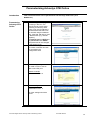
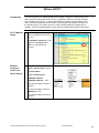
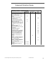
Application
Flexible packaging
machine
Inspection and testing
machine
Assembly lines
Baggage handling
system
Premium Magelis Altivar Advantys STB on Ethernet_EN.doc
Description
Image
These machines are often
connected upstream of a larger
packaging or filling plant as
feeder system components.
Components are inspected and
tested with this application.
As standalone machines, these
testing machines are integrated
into complete lines.
As part of a complete assembly
line, products are assembled
and transported in these
machines.
Using this application baggage
is monitored and transported at
airports.
Schneider Electric
3
System
Introduction
The system chapter describes the architecture, the dimensions, the quantities and different
types of components used within this system.
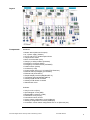
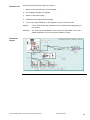
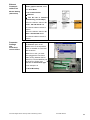
Architecture
General
The Distributed Peripheral architecture of the system comprises of a central station with a
PLC and five remote substations with various components.
The central station essentially comprises of a PLC (Unity - Premium) with integrated
Ethernet and CANopen connection, a graphic HMI (XBTG) display, two motor starters
(TeSysU) and two variable speed drives (ATV31). A 7-port switch is used to connect the
remote stations to the Ethernet.
As Ethernet nodes, the five remote substations each have a 4-port hub with an interfaced
Advantys STB Ethernet coupler.
Remote station 1 comprises of an Advantys STB island (Ethernet) with two directly
connected motor starters (TeSysU), a graphic HMI (XBTG) display, and a variable speed
drive (ATV71). They are all connected to the Ethernet via an Ethernet switch.
Remote station 2 comprises of an Advantys STB island (Ethernet) with two directly
connected motor starters (TeSysU), and two variable speed drives (ATV31), which are
connected to the STB-CANopen extender via CANopen. A Magelis (XBTN) display, which
communicates with the STB-NIP via Modbus, is used for local visualization.
Remote station 3 comprises of an Advantys STB island (Ethernet) and three Advantys FTB
I/O modules which are connected to the STB-CANopen extender via CANopen.
Remote station 4 comprises of an Advantys STB island (Ethernet) and four variable speed
drives (ATV31), which are connected to the STB-CANopen extender via CANopen. A
Magelis text HMI (XBTN), which communicates with the STB-NIP via Modbus, is used for
local visualization.
Remote station 5 comprises an Advantys STB island (Ethernet) with four directly
connected motor starters (TeSysU) and two Advantys FTB I/O modules, which are
connected to the STB-CANopen extender via CANopen. A Magelis text HMI (XBTN), which
communicates with the STB-NIP via Modbus, is used for local visualization.
The interface between the PLC, the variable speed drives and the TeSysU motor starters (in
future) is:
In the main control cabinet via CANopen and between the PLC and remote ATV71 via
Ethernet-Modbus/TCP (via a switch).
In the remote STB I/O islands (STB) the ATV31 and FTB IP67 I/O are interfaced via the
CANopen extender.
The 20 connected AC motors are operated and controlled from the Magelis XBT-G operator
and display terminal.
Protection is provided for with safety modules (Preventa), emergency-off switches and
emergency-off master switches.
Premium Magelis Altivar Advantys STB on Ethernet_EN.doc
Schneider Electric
4
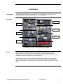
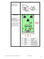
Layout
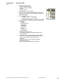
Components
Hardware:
Master switch (NSC100 Compact)
24 V power supply (Phaseo)
ATV31 and ATV71 variable speed drives
TeSysU direct starter
Motor circuit breaker (GV2)
Category 4 safety modules (Preventa)
Emergency-off switch (XALK)
Emergency-off master switch (VCF02GE)
Position switch (XCSA)
Contactors (LC1D)
Control system (PLC) incl. I/O cards (TSX Premium)
Ethernet switch (managed) (ConneXium)
Ethernet hub (ConneXium)
Graphic display terminal (Magelis XBT-G)
Text display terminal (Magelis XBT-N)
Advantys STB remote I/O island
Advantys FTB remote I/O island
Standard AC motor
Software:
Unity Pro V2.0.2 (PLC)
Vijeo Designer V4.2.0 (HMI)
Magelis XBT-L1000 V4.3 (HMI)
PowerSuite V2.0 (ATV31)
PowerSuite Launch ATV37
SyCon system configuration V2.9 (CANopen)
Advantys configuration tool V2.00 (CANopen)
ConneXium 10/100 switch configuration tool V1.01 (Ethernet port)
Premium Magelis Altivar Advantys STB on Ethernet_EN.doc
Schneider Electric
5
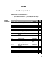
Quantities of
Components
For a complete and detailed list of components, the quantities required and the order
numbers, please refer to the components list at the rear of this document.
Degree of
Protection
Not all the components in this configuration are designed to withstand the same
environmental conditions. Some components may need additional protection, in the form of
housings, depending on the environment in which you intend to use them. For
environmental details of the individual components please refer to the list in the appendix of
this document and the appropriate user manual.
Technical
Data
Mains voltage
Power Requirement
Drive Power Rating
Motor brake
Connection
Safety Level
Safety Notice
The standard and level of safety you apply to your application is determined by your
system design and the overall extent to which your system may be a hazard to people
and machinery.
400V AC
~ 11 kW
0.37 kW, 0.55 kW
none
5x 2.5mm² (L1, L2, L3, N, PE)
Cat. 3 (optional)
As there are no moving mechanical parts in this application example, category 3
(according to EN954-1) has been selected as an optional safety level.
Whether or not the above safety category should be applied to your system should be
ascertained with a proper risk analysis.
This document is not comprehensive for any systems using the given architecture and
does not absolve users of their duty to uphold the safety requirements with respect to the
equipment used in their systems or of compliance with either national or international
safety laws and regulations
Dimensions
The dimensions of the devices used, e.g., the PLC, variable speed drive and power
supply, support installation inside a control cabinet measuring 1200x1800x600 mm
(WxHxD) for the main cabinet and 600x600x400 mm (WxHxD) for the remote cabinets.
The display terminal, the display elements and the emergency-off switch can be built into
the door of the control cabinet.
Premium Magelis Altivar Advantys STB on Ethernet_EN.doc
Schneider Electric
6
Installation
Introduction
This chapter describes the steps necessary to set up the hardware and configure the
software required to fulfil the described function of the application.
Assembly
Remote 3
Mainpanel
Remote 4
Remote 1
Remote 5
Remote 2
Subdivision of main cabinet and remote cabinets
Notes
The programming of this application can be used as a basis for plant and machinery
needing a larger number of drives with a whole range of different requirements and
acquiring their input and output data centrally via the PLC. Each of the motors is controlled
separately by the PLC via Ethernet or the CANopen bus.
The components listed in the next chapter represent just a selection of the components
required. In particular, the number of motors used and their allocation to variable speed
drives is determined by your actual application (the number of inputs and outputs may also
vary).
Premium Magelis Altivar Advantys STB on Ethernet_EN.doc
Schneider Electric
7
Hardware
General
The components designed for installation in a control cabinet, i.e., safety modules, line
circuit breakers, contactors, and motor circuit breakers, can be snapped onto a 35 mm
top-hat rail.
The master switch, Premium PLC, Phaseo power supply unit, and Altivar variable speed
drive are screwed directly onto the mounting plate. If you are using the Altivar 31,
these components can also be snapped onto a top-hat rail using an adapter.
The emergency-off and door-safety switches, as well as the housing for display and
acknowledge indicators, are designed for backplane assembly in the field; with the
exception of the door-safety switch, all switches can also be installed directly in a
control cabinet (e.g., in cabinet door) without their enclosing housing.
There are two options for installing XB5 pushbuttons or indicator lamps: These
pushbuttons or switches can be installed either in a 22 mm hole, e.g. drilled into the
front door of the control cabinet or in an XALD-type housing suitable for up to
5 pushbuttons or indicator lamps. The XALD switch housing is designed for backplane
assembly or direct wall mounting.
The operator and display terminal requires a cutout to be made in the front of the
housing. It is then attached to the housing by means of brackets with screws.
400 V / 3-phase AC wiring for the load circuits (ATV, TeSysU).
240 V AC wiring for the power supplies.
24 V DC wiring for the ATV control circuits and PLC power supply, operator and display
terminal, Ethernet switch and hub, HMI.
The individual components must be interconnected in accordance with the detailed circuit
diagram in order to ensure that they function correctly.
Ethernet lines using pre-assembled cables are laid between the PLC and remote
substations for the communications link.
In addition, CANopen bus lines are laid between the PLC and the variable speed drives in
the main cabinet and in each of the remote substations, between the STB I/O islands and
the variable speed drives or IP67 I/O modules.
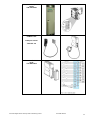
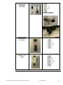
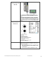
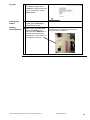
Master switch
NSC 100 compact
EMERGENCY-OFF
switch
(with overload
protection)
XALK178G
Premium Magelis Altivar Advantys STB on Ethernet_EN.doc
Schneider Electric
8
Selector and
pushbutton switch
XB5
Safety relay
Preventa
XPS-AF5130
Safety relay
Preventa
XPS-AK311144
Motor circuit breaker
Circuit breaker (shortcircuit protection)
GV2-L
Motor contactors
LC1D
Premium Magelis Altivar Advantys STB on Ethernet_EN.doc
Schneider Electric
9
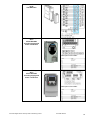
Miniature circuitbreakers
Mutil9 – 1 to 3-pole
C60H Cx
C60N Cx
Power supply
ABL7RE2405
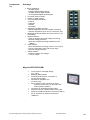
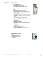
PLC
Premium
TSX P57 2634
Premium Magelis Altivar Advantys STB on Ethernet_EN.doc
1-
PLC display LEDs
2-
ETH display LEDs
3-
RESET button
4-
PADT connector (TER
socket)
5-
PADT connector (AUX
socket)
6-
RJ45 Ethernet socket
7-
Slot for memory
expansion module in
PCMCIA format (type 1)
8-
Slot for communication
card in PCMCIA format
(type 3)
Schneider Electric
10
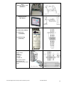
Premium PLC power
supply
TSX PSY 2600
Premium PLC
PCMCIA card
CANopen master
TSX CPP 110
Premium PLC I/O
cards
TSX DEY16D2
Premium Magelis Altivar Advantys STB on Ethernet_EN.doc
Schneider Electric
11
Premium PLC I/O
cards
TSX DSY16T2
ATV31 variable speed
drive
ATV31H037M2
including supply and
motor connection
Description of terminals:
ATV71 variable speed
drive
ATV71H075N4
including supply and
motor connection
Description of terminals:
Premium Magelis Altivar Advantys STB on Ethernet_EN.doc
Schneider Electric
12
ATV71 variable speed
drive
Ethernet option card
VW3A3310
Magelis operator and
display terminal
XBT-G2330
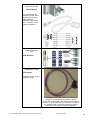
TeSysU motor starter
Power base (LUB12)
Control unit
(LUCB05BL)
Parallel wiring
(LULFC00)
TeSysU
Motor starter
LUB12
LUCB05BL
LUFC00
LU9BN11N
The power-related
components are
determined by the motor
used.
Premium Magelis Altivar Advantys STB on Ethernet_EN.doc
Schneider Electric
13
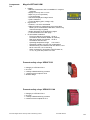
Ethernet switch
499 NES 271 00
manageable
100/10 MB/s
V24 service interface:
via cable 490NTRJ11
Ethernet switch
499 NES 181 00
100/10 MB/s
Ethernet hub
499 NEH 10410
10 MB/s
Premium Magelis Altivar Advantys STB on Ethernet_EN.doc
Schneider Electric
14
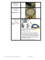
Magelis HMI
XBT-N401
1 - Front
2 - SubD25 serial interface
3 - 3-wire terminal for 24 V DC supply
4 – Mini DIN printer connection (to be used later)
Advantys STB
Advantys STB
Ethernet bus
adapter
STB NIP 2212
Premium Magelis Altivar Advantys STB on Ethernet_EN.doc
Schneider Electric
15
Advantys STB
Field power
supply
STB PDT 3100
Note:
The output
power supply
can be
deactivated
independently of
the inputs (e.g.,
in case of an
emergency off).
Advantys FTB
FTB 1CN12E04
FTB 1CN08E08
Advantys FTB
Power supply
and bus
connection
For the assignment of the sensor inputs and actuator outputs,
please refer to the product description of the modules concerned.
Premium Magelis Altivar Advantys STB on Ethernet_EN.doc
Schneider Electric
16
Software
General
You will need to install the Unity Pro programming software to program the TSX Premium
PLC and the SyCon software to configure the CANopen bus.
You will also need the Vijeo Designer and XBTL1000 software to configure the HMI
displays and to create the necessary user screens.
To maximize user-friendliness in respect of parameterization, archiving and simulation for
the variable speed drive (ATV31/71), install the PowerSuite software (PowerSuite Launch
ATV71).
You will need the ConneXium switch tool to configure the ports for the Ethernet-managed
switch (NES27100).
The following installation requirements apply in respect of all software packages:
Operating system: Windows 2000 (SP1 minimum) or Windows XP
Required hard drive memory: At least 2.4 GB, 4.4 GB recommended
RAM: At least 512 MB, 1024 MB recommended
Processor: Pentium III or higher with min. 800 MHz, 1.2 GHz recommended
Interfaces: Serial interfaces as a minimum, USB recommended in addition
Additional software:
Internet Explorer 5.5 or higher
The software tools have the following default install paths:
Unity Pro
C:\Program Files\Schneider Electric\Unity Pro
Premium Magelis Altivar Advantys STB on Ethernet_EN.doc
Schneider Electric
17
Vijeo Designer
C:\Program Files\Schneider Electric\VijeoDesigner
Magelis XBT L1000
C:\Program Files\Schneider Electric\XBT-L1000
Advantys configuration software
C:\Program Files\Schneider Electric\Advantys
PowerSuite ATV31
C:\Program Files\Schneider Electric\PowerSuite.Launch
PowerSuite ATV71
C:\Program Files\Schneider Electric\PowerSuite Launch
ATV71
SyCon
C:\Program Files\Schneider\SysCon
ConneXium switch configurator
......C:\Program Files\Schneider Electric\Ethernet Switch
Configurator 1.01\
Premium Magelis Altivar Advantys STB on Ethernet_EN.doc
Schneider Electric
18
Communication
General
PLC-configured I/O scanner functions are used to transmit data to and from the PLC. The
HMIs read/write their data automatically.
The methods of communication below are used between devices:
-
Modbus/TCP
Webserver
CANopen
Serial Modbus
Parallel cabling
Modbus/TCP Ethernet connection is used between the PLC and the main HMI (Magelis
graphic terminal). The Ethernet cable is used either for connection via a hub or switch or
for a direct connection with a crossed Ethernet cable.
Other, remote HMIs (Magelis graphic and text terminals) are operated either directly via
Ethernet or at the Modbus interface on the STB island.
An additional Ethernet port, which can be used to exchange data with other systems
(other PLCs, data acquisition systems, etc.), can also be provided as an option on
the PLC. This can also be used as a programming interface.
In addition to the serial interfaces, the Magelis XBTG2330 terminals used also have
an integral Ethernet port. The HMI is then connected directly to the MB/TCP
Ethernet via the RJ45 socket.
The remote Advantys STB stations are connected directly to the MB/TCP Ethernet via
RJ45 sockets. Advantys FTB I/O modules or Altivar 31 variable speed drives are
connected to each of these STB islands via the CANopen extender. In addition, at
three stations XBTN text displays are connected in series to the STB network
interface module via Modbus.
The ATV71 variable speed drives are connected directly to the MB/TCP Ethernet via
RJ45 sockets.
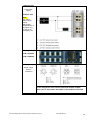
Ethernet
Table showing the Ethernet data transmission rates for the products:
Transmission
rates
Premium Magelis Altivar Advantys STB on Ethernet_EN.doc
Schneider Electric
19
Web Servers
Web servers are integrated into the following products used in this application:
TSX Premium TSXP572634M CPU with Ethernet integration
Advantys STB NIP2212 IP20 I/O station
Altivar ATV71 variable speed drive
Using Internet Explorer, you can access the web pages included in the above
products to edit or view parameter settings or diagnostics data (for communication or
device parameters).
Communications
CANopen is used for communications in the main control cabinet between the
variable speed drive (ATV31) and the PLC (TSX Premium). A CANopen bus cable
must be connected between the PLC and each variable speed drive. The CANopen
machine bus on the STB CANopen extender is also used. IP67 I/Os (Advantys FTB)
and variable speed drives (ATV31) in the remote stations are connected to this.
The ATV31 drives are connected to a CANopen junction box (VW3CANTAP2).
Two ATV31 drives can be connected to the latter via a special cable
(VW3CANRR1) with RJ45 connectors.
Modbus SL is used between the Advantys STB network interface module (NIM) and
the text HMI.
Parallel cabling uses a pre-assembled cable to connect the STB I/O island to the
motor starter. This rules out the possibility of cabling errors.
Station Overview
Premium Magelis Altivar Advantys STB on Ethernet_EN.doc
Schneider Electric
20
Topography
The Modbus TCP, CANopen and Modbus bus systems are used in this
application.
The devices below are networked via Modbus TCP:
TSX Premium, PLC1 with IP address 192.168.100.50
Magelis main panel XBT-G, HMI 0, IP address 192.168.100.52
Magelis sub-panel XBT-G, HMI1, IP address 192.168.100.53
Ethernet-managed switch NES, ETH0, IP address 192.168.100.55
Ethernet hub NEH, ETH1, ETH2, ETH3, ETH4,
Ethernet-managed switch NES, ETH5, IP address 192.168.100.60
ATV71 variable speed drive, MOT11, IP address 192.168.100.65
Advantys STB island 1, STB1, IP address 192.168.100.61
Advantys STB island 2, STB2, IP address 192.168.100.62
Advantys STB island 3, STB3, IP address 192.168.100.63
Advantys STB island 4, STB4, IP address 192.168.100.64
Advantys STB island 5, STB5, IP address 192.168.100.66
The devices below are networked via CANopen:
Two Altivar ATV31 drives (MOT1, MOT2) in the main cabinet on the
CANopen master CPP110 on the PLC, bus addresses 31, 32
Two (MOT21, MOT22) or four Altivar ATV31 drives (MOT31, MOT32,
MOT33, MOT34) in the remote cabinets on the CANopen extender on
STB island 2, STB2, and STB island 3, STB3, bus addresses 31, 32 or
27 to 30.
Two (FTB31, FTB32) or three Advantys FTB I/O modules (FTB41,
FTB42, FTB43) in the remote cabinets on the CANopen extender on
STB island 4 (STB4) bus addresses 31, 32 or 31 to 33.
The devices below are interfaced via Modbus:
Three Magelis HMI XBT-N (HMI2, HMI3, HMI5) on the Modbus
interfaces on STB islands 2, 3 and 5, bus address 1 in each case.
Two TeSysU direct starters (MOT2, MOT3) in the main cabinet are connected by
direct wiring.
TeSysU direct starters in the remote cabinets are connected to the STB islands
by direct wiring (MOT12, MOT13 STB1, MOT23, MOT24 STB2, MOT51,
MOT52, MOT53, MOT54 STB5)
Premium Magelis Altivar Advantys STB on Ethernet_EN.doc
Schneider Electric
21
Ethernet
IP-Addresses
The devices need a network identifier in order to communicate via Ethernet. This is the IP
address, with a 4x3-digit number (digit groups separated by dots).
The first three groups of digits in the IP address represent the network, while the 4th group
represents the actual device.
Example: 192.168.100.61 STB island address 61 in the local network for machine
192.168.100.
In order for a "universal" IP address to be assigned to each Ethernet device, however, the
user needs to have an initial point of access. This is provided by the MAC address on the
chip installed by the manufacturer. The MAC address is printed on every Ethernet device
label.
The following methods can be used to assign an IP address to an Ethernet device:
Device allows IP assignment via its own operating menu (e.g., ATV71)
Device supports BOOTP or role name functionality (e.g., STB)
Device supports DHCP server functionality (e.g., high-end Unity CPU)
Device has a WebServer (e.g., STB, ATV71, ETY, NOE, NES)
Device allows parameter setting via a terminal program (e.g., NES)
Not all Schneider Electric Ethernet devices support all of the above methods.
There is no standard, generic method for assigning IP addresses to Ethernet
devices. You must therefore consult the appropriate product documentation.
MACAddresses
(hex)
Every Ethernet device has a
unique manufacturer address
(MAC address).
Some examples are shown below:
Manufacturer code: 80F4 hex =
TELEMECANIQUE
MAC address 00 80 F4 80 FD
6D
ATV71 Ethernet Option Card
Ethernet Switch NES27100
MAC address
00 80 63 1A E6 04
Premium Magelis Altivar Advantys STB on Ethernet_EN.doc
Schneider Electric
22
TSX Premium PLC
TSX P57 2634M
1) Serial link between
PC with Unity Pro and
PLC (TER/AUX), using
cable TSX PCX 1031
2) The Ethernet
interface is used for the
IO scanner and other
PLC services. It can also
be used as a
programming interface
(Unity Pro). A switch or
hub and an Ethernet
cable are required to
establish an Ethernet
connection.
Programming
For the purpose of
programming, cable TSX
PCX 1031 is used to
establish a connection
between the serial
interfaces on the PC and
PLC. Alternatively, an
Ethernet link can be
used, once the Ethernet
port has been configured.
CANopen master
TSX CPP110
The TSX CPP 110
CANopen interface card
(1) is inserted into the
second PCMCIA card slot
on the Premium CPU.
The outgoing bus from
this card terminates in a
connector (2) for the
outgoing CANopen bus.
The connector is
mounted on a top-hat rail
and has a 9-pin sub D
socket.
Communication cable
PC <--> PLC
PCX1031
Default setting: 3
Programming setting:2
Premium Magelis Altivar Advantys STB on Ethernet_EN.doc
Schneider Electric
23
ATV31
CANopen connection
(RJ45) on ATV32
variable speed drive
ATV31
VW3CANTAP2
The connection to the
CANopen bus is
established using junction
box VW3CANTAP2 and
cable VW3CANRR1.
In addition, the incoming
and outgoing CANopen
cables must each be
connected to the junction
box.
Premium Magelis Altivar Advantys STB on Ethernet_EN.doc
Schneider Electric
24
ATV71
VW3A3310
Ethernet card
The connection to the
Ethernet is established
using the ATV71 option
card via the RJ45
connection.
Magelis
XBT-G2330
The connection to the
PLC is made via Ethernet
cable 490NTW00003.
There is an RJ45 socket
on the side of the HMI for
this purpose.
Ethernet cabling
Switch
499NES27100
Examples
1: Ethernet patch cable (CAT-5) with RJ45
connectors
Magelis XBTN HMI
programming cable
XBT Z915
for programming the
HMI (XBTN) via the
serial interface on the
PC, with HMI software
(XBT-L1000).
Premium Magelis Altivar Advantys STB on Ethernet_EN.doc
Schneider Electric
25
Advantys STB
HMI XBT-N data cable
XBT Z988
The XBTZ988 data cable is required to connect the
local HMI (D-sub, 25-pin) to the Advantys STB (CFG
port).
This allows the distributed I/O data on the fieldbus
island to be displayed on site directly, without a
PLC. Data can also be exchanged between the HMI
device and the PLC via the so-called HMI/PLC data
area.
Advantys STB
Ethernet connection
STB NIP 2212
1 Ethernet interface
2 MAC ID
3 Top rotary switch
4 Bottom rotary switch
5 Space to enter the IP address
6 Power supply interface
7 LED panel
8 Card slot for the memory card
9 Cover for CFG port
The two NIM rotary switches (3/4) can be used to
define how an IP address is assigned. There are two
options for allocation:
1. Via a central address server (e.g., in the PLC). The
MAC address (BOOTP) or “ROLE NAME” is used
for identification.
2. Or the internal IP address (INTERNAL) is used.
Premium Magelis Altivar Advantys STB on Ethernet_EN.doc
Schneider Electric
26
Advantys STB
Programming cable
STB XCA 4002
for programming the
Advantys via the serial
interface from the PC
(with Advantys
software). Alternatively,
the connection can be
made via Ethernet.
Advantys STB
CANopen extension
card
STB XBE 2100
Advantys FTB
CANopen bus cable
FTX CN32xx
xx stands for the varying
lengths of cable.
FTXCN32xx cables are used for the CANopen
connection. Provided that two FTBs are directly
connected to one another, the cables can be used as
they are. If, on the other hand, a connection is made to
the Advantys STB, one of the connectors must be
removed and the strands attached separately.
Premium Magelis Altivar Advantys STB on Ethernet_EN.doc
Schneider Electric
27
Advantys FTB
CANopen bus
terminating resistor
FTX CNTL12
Advantys FTB
Power supply cable
FTX DP22xx
xx stands for the varying
lengths of cable.
TeSysU - Advantys
Connection cable
LU9R10
Used to connect the
Advantys STB EPI2145
module.
1 - Advantys module STB EPI2145 *)
2 - Communication module LUF C00 (parallel
connection)
3 - Connection cable LU9410
*) The STB EPI 2145 is an Advantys STB special
module that establishes parallel cabling between an
Advantys STB and up to four reversible TeSys U
units. Each of the four channels on the STB EPI 2145
comprises two outputs (start forwards and start
backwards) and three inputs (ready for operation, run
message and error status).
This combination precludes cabling errors.
Premium Magelis Altivar Advantys STB on Ethernet_EN.doc
Schneider Electric
28
Implementation
Introduction
Function
The implementation chapter describes all the steps necessary to initialise, to configure, to
program and start-up the system to achieve the application functions as listed below.
1. With the exception of the safety functions, the entire application is controlled via the
PLC. For this purpose, in the PLC, the input signals, the information from the drives
and the inputs are analyzed via the HMI and the drives are controlled and the outputs
set on the basis of this data.
2. Independently of the PLC, the application features two Category 3 safety circuits for
the emergency-off functions. When tripped, these disconnect the power supply to the
drives and PLC outputs and inform the PLC accordingly.
3. Each type (ATV31 and ATV71) has a separate state machine in the PLC to control
the drives. The state machine converts motion commands, e.g., "Turn left at
1400 rpm" or "Acknowledge error", into a control signal for the drives. The state
machine is based on the DriveCom profile in all cases (to ensure that the state
sequence remains the same for all drive types). However, as the requirements placed
on the drives are not always the same and the functions to be implemented vary, the
following functions are supported:
ATV31: Travel at two different velocities and in two directions
ATV71: Travel at various speeds, parameter transfer
4. As the ATV71 can run without the DriveCom state machine in some settings, direct
control via the bus, for example, is supported for an ATV71.
5. The application can run in automatic mode, which is controlled via a sequencer and
features one sequence for a variety of drive functions.
6. As well as displaying up-to-date information about the application, the HMI provides
access to application controls. This usually involves switching between manual and
automatic mode. The drives can be controlled individually in manual mode.
The PLC program, therefore, represents a framework for a typical application but without
simulating any of the actual functions of a specific machine.
When the power supply is switched on via the master switch, the variable speed drives,
motor starters, PLC and Ethernet switch/hub initialize. After initialization they assume a
basic status, i.e., the motors are still switched off, and they await inputs from the operator.
The operator and display terminal also goes through an initialization phase when it is
turned on and then switches to a general status display, which among other things signals
the availability of communication to the PLC.
Premium Magelis Altivar Advantys STB on Ethernet_EN.doc
Schneider Electric
29
Function ctd.
Startup instructions and description of functions:
1. Switch on all fuses and motor circuit-breakers
2. Acknowledge emergency-off signals
3. Switch on the master switch
4. Establish a safe status and acknowledge
5. You can now select MANUAL or AUTOMATIC mode on the main screen
Manual:
On the TEST screen the individual motors can be moved independently of
one another.
Automatic:
The various speed parameters can be set on the SETTINGS screen. The
default parameters can be set using the DEFAULT switch.
Functional
Layout
Premium Magelis Altivar Advantys STB on Ethernet_EN.doc
Schneider Electric
30
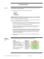
Procedure
Proceed as follows to optimize the setup time of the individual products:
1. Define the communication addresses for the individual devices (IP addresses for
Ethernet and CANopen addresses for slaves)
2. Parameterize the ATV31 and ATV71 drives (bus parameters, motor parameters,
control profile).
3. Parameterize the remote I/O stations (IP20 STB, IP67 FTB)
4. Use the SyCon software to parameterize the CANopen bus (parameters, PDO
configuration and exchange, SDO for bus start)
5. Use the Unity Pro software to parameterize the MB/TCP Ethernet bus (bus
parameters, I/O scanner)
6. Program the PLC (basic configuration, communication, variables, blocks for drives,
manual mode, automatic mode).
7. Configure and program the HMI (data areas, communication, data display, operator
controls).
Proceeding in the sequence described above will ensure that the relevant information can
either be imported directly or entered manually from the previous action.
Control program for PLC using Unity Pro XL
Configuration of CANopen bus using SyCon
Configuration of remote I/O stations (Advantys STB/FTB) using Advantys Config Tool
Configuration of operator and display terminals (XBT-G) using Vijeo Designer
Configuration of operator and display terminals (XBT-N) using XBT-L1000
Configuration of variable speed drives (ATV31) using Power Suite - optional
Configuration of variable speed drives (ATV71) using Power Suite Launch ATV71 - optional
Configuration of Ethernet switch 499NES27100 using DIP switches + ConneXium Switch
Tool
Configuration of Ethernet hub 499NES18100 using DIP switches
Configuration of Ethernet hub 499NEH10410 using DIP switches
Configuration of motor starters (using switches)
Premium Magelis Altivar Advantys STB on Ethernet_EN.doc
Schneider Electric
31
Communication
Introduction
This chapter describes the data passed via the communications bus (e.g. Modbus
TCP and CANopen) that is not bound directly with digital or analog hardware.
The list contains:
The device links
Direction of data flow
symbolic name and
PLC-configured I/O scanner functions are used for sending data to and from the PLC.
The HMIs read/write their data automatically.
Device Links
Premium Magelis Altivar Advantys STB on Ethernet_EN.doc
Schneider Electric
32
Device List
The Modbus TCP, CANopen and Modbus bus systems are used in this application.
The devices below are networked via Modbus TCP:
- TSX Premium
PLC1
- Magelis main panel XBT-G
HMI0
- Magelis sub-panel XBT-G
HMI1
- Ethernet-managed switch NES ETH0
- Ethernet hub NEH
ETH1, ETH2, ETH3, ETH4
- Ethernet-managed switch NES ETH5
- ATV71 variable speed drive
MOT11
- Advantys STB island 1
STB1
- Advantys STB island 2
STB2
- Advantys STB island 3
STB3
- Advantys STB island 4
STB4
- Advantys STB island 5
STB5
The devices below are networked via CANopen:
- Two Altivar ATV31 drives (MOT1, MOT2) in the main cabinet on the
CANopen master CPP110 on the PLC
- Two (MOT21, MOT22) or four Altivar ATV31 drives (MOT31, MOT32,
MOT33, MOT34) in the remote cabinets on the CANopen extender on STB
island 2, STB2, and STB island 3, STB3
- Two (FTB31, FTB32) or three Advantys FTB I/O modules (FTB41, FTB42,
FTB43) in the remote cabinets on the CANopen extender on STB island 4
(STB4).
The devices below are interfaced via Modbus:
- Three Magelis HMI XBT-N (HMI2, HMI3, HMI5) on the Modbus interfaces
on STB islands 2, 3 and 5
Two TeSysU direct starters (MOT2, MOT3) in the main cabinet are connected by
direct wiring.
TeSysU direct starters in the remote cabinets are connected to the STB islands by
direct wiring (MOT12, MOT13 STB1, MOT23, MOT24 STB2, MOT51,
MOT52, MOT53, MOT54 STB5).
Premium Magelis Altivar Advantys STB on Ethernet_EN.doc
Schneider Electric
33
General
Addressing
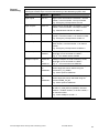
The PLC example program uses different hardware, discretes and memory words. The
following list contains keys to aid the understanding of the addressing system used.
Type
Address
Comment
Digital Inputs
%Ir.m.x
Digital inputs are hardware orientated: r as Rack
number, m as slot number, x as Input number.
E.g.: Emergency Off response at %I0.3.0
Digital Outputs
%Qr.m.x
Digital outputs are hardware orientated: r as Rack
number, m as slot number, x as output number
E.g.: Manual Mode Indicator at %Q0.5.1
Analog Inputs
%IWr.m.c
Analog inputs are hardware orientated: r as Rack
number, m as Slot number, c as channel number.
E.g.: Emergency Off response at %IW0.3.0
Analog Outputs
%QWr.m.c
Analog outputs are hardware orientated: r as
Rack number, m as Slot number, c as channel
number.
E.g.: Emergency Off response at %QW0.3.0
CANopen Inputs
%MW0 to
%MW31
CANopen-Inputs are written as Memory Words,
single bits can be accessed as %MWi.x.
E.g.: 2nd ATV Status word at %MW2
CANopen Outputs
%MW100
to
%MW131
CANopen-Outputs are read as Memory words,
single bits can be accessed as %MWi.x.
E.g.: 3rd. ATV control word at %MW104
Data for Visu
%MW200
to
%MW299
Data for the visualisation is stored in memory
words. Single bits can be written using the
function BIT_TO_WORD
E.g.: Motor speed at %MW220
Data from Visu
%MW300
to
%MW399
Data from the visualisation is stored in memory
words. Single bits can be extracted using the
function WORD_TO_BIT
E.g.: Motor speed at %MW220
CANopen Status
%CHr.m.c
CANopen Status data can be read from the data
structure T_COM_CPP110 (IODDT). ChannelAddress: r as Rack number, m as Slot number, c
as channel number.
E.g.: Status CANopen %CH0.1.1
Premium Magelis Altivar Advantys STB on Ethernet_EN.doc
Schneider Electric
34
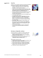
HMI
Introduction
In this application, two Magelis XBT-G 2330 HMIs connected to the PLC via Ethernet
are used.
Three Magelis XBTN401 terminals connected to the Advantys STB islands are also
used. They are described in a separate chapter later on.
Vijeo Designer software is used to configure and program the graphic terminal. The
steps to be taken in order to create and upload a program are described on the
following pages.
Setting up the HMI is done as follows:
Function
Overview
1
Vijeo Designer function overview
Create new project (specify platform, hardware, communication).
Communication settings
Set up new variables
Set up animations
Check the project and download it
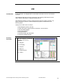
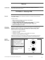
Overview of example project
The Vijeo Designer environment
consists of the following
elements:
1 Navigator
2 Info Display
3 Inspector
4 Data List
5 Feedback Zone
6 Toolbox
Premium Magelis Altivar Advantys STB on Ethernet_EN.doc
Schneider Electric
35
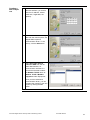
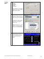
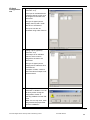
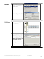
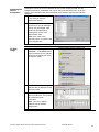
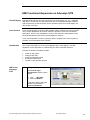
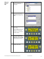
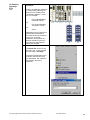
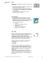
Creating a
New Project
1
When Vijeo Designer starts up,
a selection window appears.
Select Create new Project and
Next.
The following screens appear
automatically.
2
Enter a project name for the
application and an optional
comment.
3
Next, select the target device
used and enter a logical name
for it.
Example project:
Target Name: Target1
Target Type: XBTG Series
XBTG Model: XBT-G2330
Continued on next page
Premium Magelis Altivar Advantys STB on Ethernet_EN.doc
Schneider Electric
36
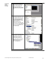
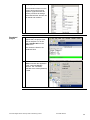
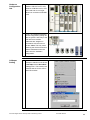
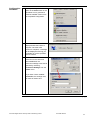
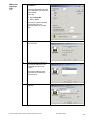
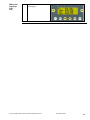
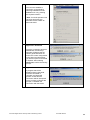
Creating a
New Project
4
In order to use the device's
Ethernet interface, you need to
enter the IP address, subnet
mask and, if applicable, the
gateway.
5
In order to be able to exchange
data with the control system, the
Magelis HMI requires a
communication driver. To set
one up, click the Add button.
6
Select Schneider Electric
Industries SAS from the list
under Manufacturer; for
communication with the PLC,
you will then be able to select
the Modbus TCP/IP driver as
Modbus TCP/IP / Modbus
Equipment under Equipment.
Ctd.
Once you have selected a
communication driver, you can
complete the creation of the new
project by clicking the OK
button.
Premium Magelis Altivar Advantys STB on Ethernet_EN.doc
Schneider Electric
37
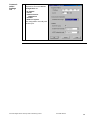
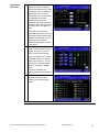
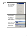
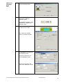
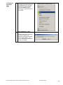
Communication
Settings
1
Once you have created the
project, Vijeo Designer will
display the workspace as
described above with an empty
edit screen on the right-hand
side.
2
To download the project, change
the settings to Ethernet. To do
this, right-click with the mouse
on the target in the Navigator
and select Download in the
Property Inspector. In order
that the project can be
transferred to the Magelis HMI,
you will need to select Ethernet
as well as the IP address and
the subnet mask.
3
The interface parameters must
be defined for the Modbus
TCP/IP driver in order to
communicate with the PLC.
Right-click with the mouse on
ModbusEquipment01 and
select Configuration….
Continued on next page
Premium Magelis Altivar Advantys STB on Ethernet_EN.doc
Schneider Electric
38
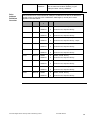
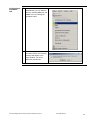
Communication
Settings
Ctd.
4
The interface parameters
required for successful device
configuration are:
IP address
Unit ID
Communication
optimization
Variable
IEC61131 syntax
The configuration must tally with
the PLC port.
Premium Magelis Altivar Advantys STB on Ethernet_EN.doc
Schneider Electric
39
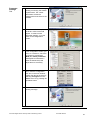
Creating
Variables
1
To create new variables in the
Navigator, select the Variable
tab at the bottom of the screen.
Right mouse click on the project
name displays a Popup-menu.
Click on New VariableNew.. .
2
To create variables, the
following information must be
entered:
Variable Name
Data Type
Data Source (External)
Device Address
3
All memory types on the PLC
can be addressed (in addition to
flags (%M), words (%MW),
double words (%MD), and
floating points (%MF), also
system bits (%S) and words
(%SW), and constant bits and
words (%K, %KW)). All data to
be displayed on the Viewer must
be transferred to one of these
types.
4
The variables created are
displayed in the Navigator,
along with their names and
addresses.
In the example project, all
variables (even Boolean
variables) are assigned to flag
words (the "Visu" section in the
PLC program is associated with
this).
Premium Magelis Altivar Advantys STB on Ethernet_EN.doc
Schneider Electric
40
Creating
Images
The process for creating animations on screens will now be described using an example
text. The functions are similar for other animation elements.
1
Example: Enter text
Selection from the menu bar.
Various icons and elements are
available in the menu bar and
the toolbox.
2
Example: Edit text
You can define:
3
Font size
Text content
Font style
etc.
Example: Animate text
Start by selecting the text
element and calling up the
dialog box by right-clicking with
the mouse. Next select the
Animation function.
You can also do this via the
Properties screen (described
above).
Continued on next page
Premium Magelis Altivar Advantys STB on Ethernet_EN.doc
Schneider Electric
41
Creating
Images
4
Animation properties:
Ctd.
Color
Position
Value
Visibility
After activation you can select a
variable for the value animation
and the display format.
5
The variable to be animated can
be entered directly in the line or
looked up by selecting the (icon)
at the end of the line (light bulb).
A variable name that has been
entered but not recognized
appears in red.
Additional functions, e.g., value
inversion, can be executed by
clicking on the calculator icon.
6
The display opposite shows the
completed startup screen in
which the separate properties
for animation and actions
appear.
Premium Magelis Altivar Advantys STB on Ethernet_EN.doc
Schneider Electric
42
7
Property Inspector
Each animation element on the
screen has its own Property
Inspector (right-click with the
mouse) via which all settings
associated with the element can
be viewed and modified.
Download
Project
1
Before being downloaded to the
graphic HMI, the project must
first be analyzed. To do this,
select Validate All from the
Build menu.
The results are listed in the
Feedback Zone.
2
Select Download All under
Build to transfer the application
to the connected Magelis
terminal. The connection
selected at the outset (Ethernet)
is used.
Premium Magelis Altivar Advantys STB on Ethernet_EN.doc
Schneider Electric
43
Application
Overview
1
The example application
features a number of displays
that can be selected by the user.
The display opposite shows the
main screen from where all
other displays can be accessed.
The application overview,
providing access to error
messages and safety indicators,
as well as to the selection of the
operating mode, also appears
here.
In principle, all screens are
structured in the same way and
all essential system status data
appears in the header. You can
switch from one screen to
another by clicking the buttons
in the footer.
2
All drives can run in manual
mode, controlled directly via the
Viewer. To do this, you must
switch to the relevant screen.
There is one button for forward
travel and another for reverse
travel. For the ATV71, you can
also specify a velocity and set
ramps by clicking on the Set
button.
The status message and
velocity display act as feedback.
3
Other screens include a
diagnostics display and an
overview of the Ethernet bus
nodes.
Premium Magelis Altivar Advantys STB on Ethernet_EN.doc
Schneider Electric
44
PLC
Introduction
Address
Definition
Overview
The PLC chapter describes the steps required for the initialisation and configuration and
the source program required to fulfil the functions.. The Unity Pro and SyCon software
tools are used for this. Proceed as follows to integrate the PLC:
Overview of address definitions
Configure communications between CANopen and the master (SyCon)
Create a new PLC project and select hardware (Unity Pro)
Configure the inputs and outputs (Unity Pro)
Configure CANopen communication (Unity Pro)
Configure Ethernet communication (Unity Pro)
Create application program (logic) (drives, manual mode, automatic mode).
Create visualization interface.
Connect to PLC and download program.
Various hardware addresses, as well as flags and flag words, are using in the PLC
example program. To facilitate orientation, an overview of the addresses used appears
below in list format.
Type
Address
Comment
CANopen inputs
%MWx to
%MWxx
CANopen inputs are written to flag words;
individual bits can be addressed via %MWi.x.
Example: 2nd ATV status word %MW2
CANopen outputs
%MWxxx to
%MWxxx
CANopen outputs are read by flag words;
individual bits can be addressed via %MWi.x.
Example: 3rd ATV control word %MW104
MB/TCP inputs
%MWxxx to
%MWxxx
Modbus/TCP inputs are written to flag words;
individual bits can be addressed via %MWi.x.
Example: 2nd ATV status word %MW200
MB/TCP outputs
%MWxxx to
%MWxxx
Modbus/TCP outputs are read by flag words;
individual bits can be addressed via %MWi.x.
Example: 3rd ATV control word %MW304
MB inputs
%MWxxx to
%MWxxx
Modbus inputs are written to flag words; individual
bits can be addressed via %MWi.x.
Example: 2nd ATV status word %MW400
MB outputs
%MWxxx to
%MWxxx
Modbus outputs are read by flag words; individual
bits can be addressed via %MWi.x.
Example: 3rd ATV control word %MW454
Data for Viewer
%MWxxx to
%MWxxx
Data for Viewer is written to flag words. Individual
bits are written via block BIT_TO_WORD.
Example: Motor velocity %MW520
Premium Magelis Altivar Advantys STB on Ethernet_EN.doc
Schneider Electric
45
Data from Viewer
Drive
Address
Definition
Overview
%MWxxx to
%MWxxx
Data from Viewer is read by flag words. Individual
bits are extracted via block WORD_TO_BIT.
Example: Motor velocity %MW620
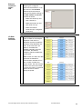
Data for drives which communicate via CANopen or MB/TCP bus devices is addressed
via flag words. An overview of PLC addresses, data length (in words) and content
appears in the table below.
Device
ATV31
ATV31
ATV71
ATV31
ATV31
ATV31
ATV31
ATV31
ATV31
Node
Addresse
s
MOT1
%MWx
2
Status, actual velocity
%MWxxx
2
Control word, setpoint velocity
%MWx
2
Status, actual velocity
%MWxxx
2
Control word, setpoint velocity
%MWx
4
Status, actual velocity, ramps
%MWxxx
4
Control word, setpoint velocity, ramps
%MWx
2
Status, actual velocity
%MWxxx
2
Control word, setpoint velocity
%MWx
2
Status, actual velocity
%MWxxx
2
Control word, setpoint velocity
%MWx
2
Status, actual velocity
%MWxxx
2
Control word, setpoint velocity
%MWx
2
Status, actual velocity
%MWxxx
2
Control word, setpoint velocity
%MWx
2
Status, actual velocity
%MWxxx
2
Control word, setpoint velocity
%MWx
2
Status, actual velocity
%MWxxx
2
Control word, setpoint velocity
MOT2
MOT11
MOT21
MOT22
MOT31
MOT32
MOT33
MOT34
Premium Magelis Altivar Advantys STB on Ethernet_EN.doc
No.
Data
Schneider Electric
46
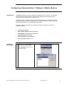
Configuring Communication CANopen - Master (SyCon)
Introduction
The SyCon software is used to configure the CANopen bus on the PLC. The individual
devices are identified as devices on the bus, then addresses are assigned and the
master function is assigned to the Premium PLC.
Subsequent steps configure the data for the individual devices to be transferred during
operation (PDO) and if necessary specify their configuration (SDO). Finally, the general
bus settings are entered, e.g. specifying the baud rate.
Proceed as follows to establish communications between CANopen and the PLC
(CANopen master):
Creating a
New Project
Create a New Project
Add CANopen Master devices (CPP110)
Add CANopen node devices (Altivar 31)
Configure Altivar 31 devices
Define CANopen bus parameters
Save the project (create *.co)
1
Start the software, then start a
new project from FileNew.
Select CANopen as the bus in
the next window.
Premium Magelis Altivar Advantys STB on Ethernet_EN.doc
Schneider Electric
47
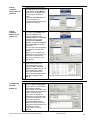
Adding
CANopen
Master Devices
(CPP110)
1
Add the PLC’s circuit card for
the CANopen bus to the project
as the master via the Master
menu item in the Insert menu,
or by using the equivalent
button.
Select the TSX CPP 110 card
in the next window. A
CANopen address and a name
must also be entered.
Adding
CANopen
Node Devices
(Altivar 31)
2
Add each drive to the project
as a node via the Node menu
item in the Insert menu.
In the next window select
Telemecanique as the Vendor
and select the type of the
corresponding Available
devices. A CANopen node ID
and a description must also
be entered.
This process must be repeated
for each drive and the other
devices.
Note: You can preselect the
manufacturer and profile in the
node filter to speed up the
search for the devices in the
selection list.
3
Once all devices have been
entered there will be two
devices altogether in the
example project. Select ID
Table in the View menu to call
up the identification table,
which summarizes all the
devices and their addresses as
well as the mapped PDO
objects.
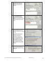
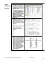
1
Double-click on the device to
open the Node configuration
window that is used for all bus
node settings including
configuration of the node at the
start of the bus and the transfer
of data during operation.
The window is divided into
three parts: the top part shows
the general configuration, the
center part shows the
predefined PDOs and the
bottom part shows the PDOs
configured for these nodes and
can also be used for
configuration or making
changes.
Configuring
Devices
Altivar 31
Premium Magelis Altivar Advantys STB on Ethernet_EN.doc
Schneider Electric
48
2
Two predefined PDOs are
selected for the ATV31 as
standard: PDO1 and PDO4.
These are not used in the
example.
3
From the predefined PDOs
(1, 4), double-click on the
receive and transmit PDOs
(PDO6) to activate them for data
transfer between the PLC and
ATV31.
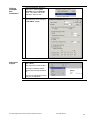
4
The Receive PDO6 and
Transmit PDO6 PDOs have
now been selected for the Altivar
31 drive.
After double-clicking on the
PDOs to be activated, the
window for setting the
transmission type appears.
For the receive PDO, select
Device profile with the event
When data has changed.
For the transmit PDO, select
Device profile and No remote
request.
5
As the COB-ID for the PDOs is
not assigned automatically at
number 5 and higher, a warning
will appear.
Premium Magelis Altivar Advantys STB on Ethernet_EN.doc
Schneider Electric
49
6
The COB-ID now has to be
entered manually for each PDO.
1. Deselect Automatic COBID allocation.
2. Modify the COB-ID for the
configured PDOs.
Note: Please note that different
Ids must be allocated for each
PDO and each ATV31. You can
use the values for PDO2, i.e.,
the values 640 + CANopen
address for the transmit PDO
and 768 + CANopen address for
the receive PDO.
7
After the transmission mode
has been selected the PDO is
automatically entered as a
configured PDO. There is no
need for additional
configuration.
You must configure a type 6
PDO to send and receive for
each variable speed drive.
Note: Click the PDO Contents
Mapping button to see the
data to be transmitted in the
selected PDO. The PDO
Characteristics button returns
you to the transmission mode
screen for the PDO.
Premium Magelis Altivar Advantys STB on Ethernet_EN.doc
Schneider Electric
50
Defining
CANopen
Bus
Parameters
Saving the
Project
1
The bus parameter window is
called up by selecting Bus
Parameter from the Settings
menu. The master has to be
selected in the bus view.
2
The transmission rate is the
only parameter to be changed,
to 500 kBit/s (kbaud).
1
Then save the SyCon project
(File->Save).
The project file is saved under
C:\Program Files\Schneider
Electric\SyCon\Project\DPETH.
co.
It is used as the basis for future
Unity Pro configuration.
Premium Magelis Altivar Advantys STB on Ethernet_EN.doc
Schneider Electric
51
Create a New PLC Project and Select Hardware (Unity Pro)
Creating a
New Project
1
After starting Unity, the first thing
you need to do is create a new
project (File->New).
2
When doing so, you must select
the correct PLC.
In our example it is
TSX Premium CPU
TSXP572634M
3
Select Configuration in the
project browser to open the
hardware configuration. Modify
the number and size of the racks
accordingly
Example project: 1 rack with 8
slots TSX RKY 8EX
4
If you are using a double-width
power supply, you must
"drag&drop" the CPU to position
1 in order for the correct power
supply to be inserted (Example:
TSX PSY 2600M)
Premium Magelis Altivar Advantys STB on Ethernet_EN.doc
Schneider Electric
52
Creating a
New Project
5
Ctd.
"Drag&drop" is also used to
move the individual modules to
the right slots
(example project: 32 digital
inputs, 32 digital outputs;
2x TSX DEY16D2,
2x TSX DSY 16T2,
1x TSX AEY414, optional
1x TSX ASY410, optional)
6
Double-click on the CPU's lower
PCMCIA slot (B) to open a
window listing the permitted
PCMCIA cards. The TSX CPP
110 card must be selected for
the CANopen bus (under
Communication).
Repeat the procedure for slot A
and enter memory card TSX
MRP C001M (or higher if
necessary).
Now save the project.
Premium Magelis Altivar Advantys STB on Ethernet_EN.doc
Schneider Electric
53
I/O Card
Configuration
1
Double-click on the relevant
module in the hardware view to
open the configuration area for
input and output cards.
Configure each card individually
and confirm your settings on
completion.
2
Digital inputs
(TSX DEY 16D2):
Eight inputs are grouped in one
channel.
Each channel (0 and 8) must be
assigned to the task to be
performed.
The inputs of channel 8 can also
be disabled (no function).
3
Digital outputs
(TSX DSY 16T2):
Eight outputs are grouped in one
channel.
Each channel (0 and 8) must be
assigned to the task to be
performed.
The behavior of each channel in
the event of a fault and on
restarting also needs to be
defined. In respect of behavior in
the event of a fault, a separate
value can be defined for each
output.
The inputs of channel 8 can also
be disabled (no function).
Continued on next page
Premium Magelis Altivar Advantys STB on Ethernet_EN.doc
Schneider Electric
54
I/O Card
Configuration
4
Ctd.
Analog inputs (optional)
(TSX AEY 414):
Each input is considered as an
individual channel, which must
be assigned to the task to be
performed.
The type of signal (current,
voltage, thermo) and a scale
also have to be entered.
The inputs can also be
smoothed using a filter function.
5
Analog outputs (optional)
(TSX ASY 410):
Each output is an individual
channel, which must be
assigned to the task to be
performed.
The type of signal (current,
voltage) and a scale also have
to be entered.
In respect of faults, a value to
which the relevant output is set
can be entered.
6
The configuration must then be
confirmed or validated. You can
do this by either closing the
configuration window or
selecting Validate from the Edit
menu.
Note: You can only save, close
and generate the project after
you have validated it.
Continued on next page
Premium Magelis Altivar Advantys STB on Ethernet_EN.doc
Schneider Electric
55
CANopen
Communication
1
Double-click on slot B again to
open the configuration of the
CANopen bus.
2
The configuration window is
divided into a number of areas.
Ctd.
On the left you can select the
association with the task being
executed, in this case the
master task.
The upper part of the window is
for selecting the restart
characteristics of the bus and
the assignment of addresses for
the input and output areas. An
automatic bus restart is
configured in the example
project. The inputs start at
address %MW0 and the
outputs at %MW100. 32 words
are provided for each area.
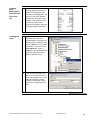
3
The most important
configuration task is transferring
the file from the SyCon software
(*.co). This can be activated by
clicking the Select Database
button.
Once the transfer is complete,
the most important data appears
underneath the file details. You
can also choose here whether to
use Unity Pro or SyCon for bus
configuration. In the example
we are using Unity.
Continued on next page
Premium Magelis Altivar Advantys STB on Ethernet_EN.doc
Schneider Electric
56
CANopen
Communication
4
Ctd.
Click the Bus configuration
button to display the individual
bus devices in a new window.
Click on one of the devices in
the list on the right-hand side of
the window to display additional
information, such as the I/O
addresses.
Note: The addresses are shown
from top to bottom in order of
their position on the bus in the
SyCon software. The CANopen
node addresses are
disregarded.
5
The configuration must then be
confirmed or validated. You can
do this by either closing the
configuration window or
selecting Validate from the Edit
menu.
Note: You can only save, close
and generate the project after
you have validated it.
Continued on next page
Premium Magelis Altivar Advantys STB on Ethernet_EN.doc
Schneider Electric
57
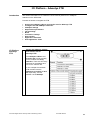
Ethernet
Communication
1
Next, select New Network
under Communication
Network in the project browser.
2
In the Add Network dialog,
specify Ethernet as the network
type and enter a name
(Ethernet_1) for the network
under Change Name. Click OK
to create the network.
3
Open the network and make the
following settings in the
sequence described:
1. Select the model family: In
the case of TSX P57
2634M, you must select
TCP/IP 10/100 Extended
connection.
2. Specify the IP address and
subnet mask.
3. Activate Address Server
4. Activate IO scanning.
Continued on next page
Premium Magelis Altivar Advantys STB on Ethernet_EN.doc
Schneider Electric
58
Ethernet
Communication
Ctd.
4
Next, click on the Address
Server tab and enter the MAC
address of the device (Advantys
STB NIP 2212 and ATV71),
along with the desired IP
address. On the NIP 2212, for
example, you will find the MAC
address printed underneath the
Ethernet port.
5
Next you need to configure
device scanning. To do this,
click on the IO Scanning tab
and enter the data relating to the
device's IP address. Note:
Details of the example project
entries are provided below.
Health Timeout
1500 ms
Time-out for a fault
Repetitive rate:
10 ms
Data exchange repetition rate
RD Master Object
%MW100
Target for read data
RD Slave Index
e.g., 5391
Start address for reading data from island
RD Length
22
Length of the read area in words
WR Master Object
%MW200
Target for write data
WR Slave Index
0
Start address for writing data to island
WR Length
11
Length of the write area in words
Note: The lengths of the read and write areas are based on the island’s I/O data
image, which also provides the start addresses.
Note: In the case of the Premium PLC, the start addresses from the Advantys
island must be reduced by one in Unity (e.g., Unity = %MW1000, ACT =
%MW1001).
Note: As well as exchanging the I/O data image, it is also possible to transfer
diagnostic data using I/O scanning. For this to happen, the value of "RD Slave
Index" must be changed to 5356, in which case the "RD length" will be 57. The
diagnostic data will then be located in the first 35 registers in the WR master object.
A detailed description of the diagnostic data is available with the Advantys Help
function.
6
Now close the configuration and confirm acceptance of the changes when the
prompt appears.
Continued on next page
Premium Magelis Altivar Advantys STB on Ethernet_EN.doc
Schneider Electric
59
Ethernet
Communication
Ctd.
7
The final step consists of
assigning the configured
network to the hardware. To do
this, switch to the hardware
view and open the network
connection by double-clicking on
the CPU network connection.
Proceed as follows:
1. Select the channel (in this
case: channel 3).
2. Select the function (in this
case: ETH TCP IP).
3. Select the network
connection (the configured
connection)
I/O Data
Address
Overview
1
The tables provide an overview
of the I/O data for the example
application. Both the PLC
addresses and the I/O platform
(Advantys STB) addresses are
given. In the case of the I/O
platform, the addresses
available externally are given.
By contrast, the internal
CANopen extension addresses
are not given.
Note: On the PLC side, two data
structures are defined for
communication with the ATV31,
each of which contains two
integer values. The first of these
values is the control word used
to convey the motion commands
and the second is used to
specify the speed.
Premium Magelis Altivar Advantys STB on Ethernet_EN.doc
Schneider Electric
60
Creating the
Application
Program
The application program logically simulates the machine and its function. This document
and the example application are only able to outline the basic framework for a program
of this type. The key steps required to create the application program are set out below:
1. Creation of variables and I/O assignment
2. Creation of the state machines for the speed drives
3. Application program and logic creation (motor control, mode control, interfaces for
visualization)
Creating
Variables
1
Variables are declared and
assigned to inputs and outputs
in the Data Editor. The following
information is required for a
variable:
Name
Type
Address (if applicable)
Init value (if applicable)
Comment
Variables are created when
they are entered in the Data
Editor table.
2
In the example program, as well
as elementary variables for
digital and analog data,
structures are used for data
exchange with the variable
speed drives.
These can be created on the
DDT Types tab in the Data
Editor. As well as a name and
comment, you need to declare
the individual elements of the
structure.
Right-click with the mouse and
select Analyze type to complete
the definition of the structure.
Once defined, the types can
then be used for variable
declarations.
Premium Magelis Altivar Advantys STB on Ethernet_EN.doc
Schneider Electric
61
Creating
State
Machines for
Speed Drives
1
DriveCom
The variable speed drives are
controlled via a state machine
(DriveCom). For this purpose, a
separate “derived function block”
(DFB) is written for each in the
example program.
The definition of a DFB also
starts in the Data Editor (DFB
tab), where the inputs and
outputs, as well as the internal
variables of the DFB, have to
be defined. The program
sections of the DFB can also be
created here.
2
The DFB is programmed in
structured text in two sections in
the example program. One
section prcesses the input data
(Status) and the other the output
data (Ctrl).
Programming is done using the
Editor, where the code can be
entered/altered. Auxiliary
functions for invoking other
function blocks are also
available.
3
The blocks are selected in the
section in which instantiation is
to take place (the simplest way
to choose a function block is to
use the Ctrl+D or Ctrl+I shortcut
and then enter the block name.
The function block can then be
positioned in the section.
For the ATV31, the function
block manages the emergency
stop, two directions of rotation,
two velocities and the fault
acknowledgement.
Continued on next page
Premium Magelis Altivar Advantys STB on Ethernet_EN.doc
Schneider Electric
62
Creating
State
Machines for
Speed Drives
4
DriveCom
Ctd.
Creating the
Logic
For the ATV71, the function
block manages the direction of
rotation, the emergency stop
and fault acknowledgement. The
velocity can be freely defined.
Furthermore, the ramps can be
modified in the speed drive (for
this purpose, a secondary
structure is provided in the block
for the associated parameters).
1
In the example program, the
application logic has been
programmed as a function block
diagram (FBD). Completed units
form a Section. This must be
created first. You do this in the
Project Browser, under
Program, in the associated task
(right-click with the mouse to
open the relevant menu).
2
Once you have created a new
section you will need to enter a
name and language for it. In the
example programs, with the
exception of automatic control,
all sections are programmed in
FBD.
Continued on next page
Premium Magelis Altivar Advantys STB on Ethernet_EN.doc
Schneider Electric
63
Creating the
Logic
3
The blocks (Ctrl+D) or popup
menu (Data Selection) can then
be called up in the section.
Other elements such as links,
negations or comments can also
be accessed in this menu or via
shortcuts.
4
A separate section in which
directions can be controlled and
parameters defined has been
provided in the program for each
individual drive. Directions of
rotation are controlled
separately for each operating
mode.
5
In the "application" section, the
operating modes are defined
and general monitoring of the
safety functions or CANopen
bus takes place.
6
A sequencer has been provided
for automatic mode to control
the machine sequence. Actions
and step enables in the next
step must be defined for each
individual step.
Ctd.
Continued on next page
Premium Magelis Altivar Advantys STB on Ethernet_EN.doc
Schneider Electric
64
Creating the
Logic
7
Data is transferred between the
PLC and Viewer in the "visu"
section. It is here that the
necessary data is written to/read
from flag words. The principle
that logic functions can only be
executed in the PLC applies.
1
Upon completion of
programming, the entire project
must be rebuilt. To do this,
select the relevant menu item or
button. BuildRebuild All
Project
2
You must define the PLC
address before establishing a
connection to the PLC (PLC
Set Address).
Ctd.
Program
Download
In this case, the Unitelway
protocol (UNTLW01) must be
selected and the PLC SYS
(standard system address)
entered as the address.
3
The connection is established by
selecting Connect from the PLC
menu or pressing the equivalent
button. For it to work, the
appropriate programming cable
must be connected to the PLC.
4
The program can now transfer
data to the PLC and the PLC
can be started up.
Note: If you want the PLC to
start as soon as the download is
complete, you must check the
relevant box before starting the
transfer.
Continued on next page
Premium Magelis Altivar Advantys STB on Ethernet_EN.doc
Schneider Electric
65
Program
Download
Ctd.
5
Confirm that you want to start
the project.
Premium Magelis Altivar Advantys STB on Ethernet_EN.doc
Schneider Electric
66
Devices
Introduction
This chapter describes the steps required to initialise and configure the devices to
attain the described system function.
I/O Platform - Advantys STB
General
This chapter describes how the Advantys I/O platform is configured using the Advantys
configuration software.
Proceed as follows:
IP Address
Assignment
Make the hardware settings, in particular the IP address
Create a new project (workspace)
Configure the hardware (network interface, power supply and I/O modules)
Configure CANopen extension communication (baud rate)
If necessary, adjust device parameters (reset inputs, settings, etc.)
Download configuration to island.
The type of IP address assignment is set via the rotary switches on the STB NIP 2212
island head. Each of the rotary switch positions that can be used to specify a valid IP
address is indicated on the housing of the STB NIP 2212. There are a total of four
different methods for assigning addresses:
Assignment of the address via BOOTP
Assignment via DHCP
Assignment of a fixed IP address via the STB NIP 2212 web page
Conversion of MAC address into an IP address
The BOOTP mechanism is described below. Details of the other methods can be found
in the product documentation or in the Advantys configuration software Help function.
BOOTP
Mechanism
1
Within the context of the
example project, the address is
assigned using the BOOTP
mechanism, as the PLC’s
Ethernet interface has a BOOTP
server, making this the simplest
method.
2
To use the BOOTP method, you
must set the top rotary switch to
the 0 position and the bottom
one to “BOOTP”.
Premium Magelis Altivar Advantys STB on Ethernet_EN.doc
Schneider Electric
67
Creating a
New Project
Hardware
Configuration
1
After starting the Advantys
software, you must create a
New Workspace…
2
To do this, you must specify the
path, the workspace name and
the name of the first island.
1
Select Ethernet network
interface module STB NIP 2212
as the island head.
2
Switch to the Parameters view
by double-clicking on the head
and adjust the maximum node
ID on the CANopen extension
as necessary. Note: This does
not need to be done in the
example project. Instead we will
use the default setting (32).
5 words are reserved for each
direction (HMI PLC and PLC
HMI) in each station to which
a Magelis HMI XBT-N is
connected.
Continued on next page
Premium Magelis Altivar Advantys STB on Ethernet_EN.doc
Schneider Electric
68
Hardware
Configuration
Ctd.
CANopen
Setting
3
Next, add the remaining
stations: STB PDT 3100, STB
DDI3610, STB DRC 3210, STB
XPE 2100 and do not forget
about bus connection STB XMP
1100.
4
Finally, the CANopen extension
can be configured by writing the
devices (ATV31 and FTB) to the
STB XPE 2100 module.
Addresses are assigned in
accordance with the order on
the bus. Note: This may mean
switching the devices around so
that the addresses match the
order set in the hardware
configuration.
1
The transfer rate for the
CANopen extension must be set
to 500 kbps via the Baud Rate
Tuning menu. This transfer rate
matches that set for the ATV31
and FTB modules.
Premium Magelis Altivar Advantys STB on Ethernet_EN.doc
Schneider Electric
69
Adjusting the
Device
Parameters
Parameters can be set for the individual devices on the Advantys island. On the
CANopen extension, parameters can only be set for the Advantys FTB, not for the
ATV31. The parameters are then transferred to the devices whenever the island is
restarted.
1 Double-click on the device (FTB
in this case) to open the
Parameters window.
2
The figure shows the settings for
the use of pin 2 of an Advantys
FTB by way of example. New
values can be specified by
entering them in the “User
defined label” field.
Note: In the case of the
example project, no values need
to be changed here.
I/O Data
Image
1
You can use I/O Image
Overview… in the Island menu
or the equivalent icon to call the
function for assigning the I/O to
the memory areas.
2
The information concerning the
selected data is displayed in the
description field.
3
Alternatively, the project can
also be printed out. The printout
will contain the same
information.
Note: The “PLC” chapter
contains a list of address
assignments.
Premium Magelis Altivar Advantys STB on Ethernet_EN.doc
Schneider Electric
70
Configuration
Download
1
Start by selecting the Build
option in the Island menu or the
equivalent icon to generate a
machine-readable version from
the completed configuration.
2
An information window will be
displayed while the build is in
progress. Once the build
process is complete, a message
will be displayed informing you
of whether or not the operation
was successful.
3
If this is the first time that a
connection to the island has
been established, the
connection settings must first be
specified by selecting
Connection Settings from the
Online menu.
If you have chosen a serial
connection, the settings must
be made as shown here.
Continued on next page
Premium Magelis Altivar Advantys STB on Ethernet_EN.doc
Schneider Electric
71
Configuration
Download
Ctd.
4
You can now establish a
connection to the island by
selecting Connect from the
Online menu or by pressing the
equivalent button. Note: If no
build operation has yet been
performed, the software will now
initiate an automatic build.
5
Once the connection has been
established, the Advantys
software will detect that the
machine-readable version
generated does not match the
current configuration in the
island and will present you with
an option to Download or
Upload. After selecting
Download, confirm the security
prompt.
6
A progress bar will be displayed
during download. Once the
download is complete, the island
will perform a reset and the
connection will be interrupted.
Once you have confirmed the
prompt, re-establish the
connection with the island.
Continued on next page
Premium Magelis Altivar Advantys STB on Ethernet_EN.doc
Schneider Electric
72
Configuration
Download
Ctd.
7
Once the connection has been
reestablished, you can start the
island by selecting Run from the
Online menu or pressing the
equivalent button.
8
Confirm the prompt. Following
successful startup, the following
message will appear in the
output window: “No errors.
Island fully operational.”
Premium Magelis Altivar Advantys STB on Ethernet_EN.doc
Schneider Electric
73
Parameterizing Advantys STB Online
Introduction
This section describes how to parameterize the Advantys STB online (via a
WebServer).
Parameterize
Advantys STB
Online
1
2
3
When the application program
is running in the PLC, the
BOOTP server is also active.
Following an Advantys STB
power cycle, the IP address is
transferred and the island can
be reached using this address
(e.g., http//192.168.100.61) and
a Web browser (e.g. Internet
Explorer).
The default login is USER and
the password is also USER.
The password can be changed
in the Security area.
The master configurator and
the master controller can both
be accessed in the
Configuration area.
The following settings should
be made in order to use an
HMI on the CFG port:
Master Controller
Reservation Time: 0
4
Master Configurator
Master: Serial
Reservation Time: 0
All of the settings should be
saved.
Premium Magelis Altivar Advantys STB on Ethernet_EN.doc
Schneider Electric
74
HMI Functional Expansion on Advantys STB
Visual Display
Advantys STB supports the local connection of a visual display unit, e.g., a Magelis
XBT-N 401. In this case, the VDU data must also be transferred between Advantys
STB and the PLC so that the drives can be operated via the local visual display unit
with the aid of the PLC.
Local Control
Local control/operation of drives is not possible without a higher level control system.
This is mainly attributable to the state machine required for control of the variable
speed drive, which is only available on the PLC and cannot be implemented locally.
The operating states of the drives can be displayed, however.
Local control/operation of motors (TeSysU) without a higher level control system is
possible, and is described in this example.
Introduction
This section describes how to set up the Magelis HMI’s visual display. The HMI
application for the XBT N401 is created using the XBT-L1000 HMI software.
Proceed as follows to integrate the HMI:
HMI on the
Advantys
STB
1
Create a new project
Configure the HMI
Create an application page
Simulate the application
Transfer to the operator terminal
Configure the HMI
The Terminal Type
Configuration window opens.
Select:
Type:
XBT N401
Protocol: Modbus
In the same dialog, select the
Modbus communication
protocol parameters.
Premium Magelis Altivar Advantys STB on Ethernet_EN.doc
Schneider Electric
75
HMI on the
Advantys
STB
Ctd.
2
Set Modbus protocol
parameters
The same parameters as those
on the Advantys STB CFG port
should be set.
These are:
Speed: 9600 Bd
Parity: Even
Click OK to close this window
and continue with the
parameterization by clicking
Next.
3
Assign project name
and click Next.
4
Enter the symbolic name and
the network address for the
connected devices in this
window.
The network address must
match that of the Advantys
STB CFG port.
5
Continue by setting the
language.
Premium Magelis Altivar Advantys STB on Ethernet_EN.doc
Schneider Electric
76
HMI on the
Advantys
STB
Ctd.
6
Do not make settings for the
terminal and dialog table.
7
After completing the basic
parameters, create the
application pages.
Text objects and links to other
pages can be created on an
application page.
8
Properties can be assigned to
the alphanumeric fields.
First, specify the variable,
which is to activate the field.
9
Select the source/target from
the Equipment drop-down list.
Enter Advantys here.
On the first screen, bit 8 of
word %MW9488 is used.
On the second screen, the
whole word %MW4097 is used.
Premium Magelis Altivar Advantys STB on Ethernet_EN.doc
Schneider Electric
77
HMI on the
Advantys
STB
Ctd.
10
Different formats are available
for the display. The first or
second text is displayed here,
depending on the bit state.
As well as the text, which has
been converted from a value,
the value itself can also be
displayed.
11
The tab also indicates whether
the variable is read-only, writeonly or read/write.
12
The application can be
simulated “offline” (without HMI
connected) using the
simulation function of the XBTL1000 software.
13
In order to download the
application from the PC to the
Magelis XBT-N401 HMI
(Transfers Export), the
XBT-Z915 communication
cable will need to be
connected.
Start the download by selecting
Export in the Transfers menu.
Premium Magelis Altivar Advantys STB on Ethernet_EN.doc
Schneider Electric
78
HMI on the
Advantys
STB
Ctd
14
The Page Tree window
contains information about the
display pages and their
connections.
15
From the individual pages,
other pages that have to be
configured accordingly can be
called.
16
The configured pages are
shown below.
AUTO or MANU mode can be
selected on the start page.
From here, you can switch to
the other screens.
17
The three state indications for
the first two TeSysU motor
controls are shown in the Manu
Mode window. The drive can
also be switched on and off.
18
As in step 17 above in drive
numbers 3 and 4 only.
Premium Magelis Altivar Advantys STB on Ethernet_EN.doc
Schneider Electric
79
HMI on the
Advantys
STB
Ctd.
19
All of the drive stati are shown
on this page.
Premium Magelis Altivar Advantys STB on Ethernet_EN.doc
Schneider Electric
80
Advantys STB & CANopen Extender Operating Behaviour
Introduction
The address and transfer rate must be specified for all the devices on the CANopen
extension.
Note: It is important to ensure that the addresses run consecutively in descending
order, starting with 32, which is the maximum start address. The start address can be
anywhere within the range of 8-32 using the Advantys software (see I/O platform
chapter). This should be taken into account when assigning addresses.
CANopen
Extension
Nodes
The maximum number of nodes on the extension is 12. The configuration described
above is capable of handling six devices without any discernible problems. Similarly,
there is no evidence to suggest that the order/address of the individual stations will be
adversely affected.
As soon as the power is switched on, the drive island devices enter the initialization
Starting
Characteristics phase, during which their own parameters are (re)set.
The Advantys STB initialization process takes the most time. During this time, the
CANopen extension starts up and parameters are transferred from the Advantys STB
to the extension devices (if such parameters have been defined in the Advantys
configuration software).
For the purpose of operating the drive island, the island (i.e., Advantys STB) and the
PLC must be able to communicate with one another. Without this active
communication, it will not be possible for the DriveCom profile of the variable speed
drives to be evaluated and controlled and they will switch to fault mode.
CANopen
Extension
configuration
Errors
Below is a description of how the bus behaves in the event of an incorrect
configuration, particularly addressing errors:
In the event of a duplicate bus address being assigned, the two devices with the
duplicate address are excluded from bus operation and no data can be exchanged
with them. Data exchange with all the other devices continues as normal and is
unaffected by this fault.
If a device on the bus has the same address as the XBE 2100 extension module,
the bus will fail to start and no data will be exchanged.
In both cases, the relevant diagnostic message will be displayed in the Advantys
software or on the island head Web page to enable the error to be determined on
startup.
Premium Magelis Altivar Advantys STB on Ethernet_EN.doc
Schneider Electric
81
I/O Platform - Advantys FTB
Introduction
This section describes how to create the remote FTB I/O platform as a CANopen
extension on the STB island.
Proceed as follows to integrate the FTB:
I/O Platform
Advantys
FTB
1
Assign the CANopen address and transfer rate for Advantys FTB
Configure the STB CANopen extension
CANopen settings
Adjust device parameters
I/O data image
Build
Connection settings
Data transfer
Application download
Start application - RUN
Assign the CANopen address
and transfer rate for
Advantys FTB
The CANopen address and
transfer rate are set manually
on the modules via rotary
switches. There are two rotary
switches for the address and
one for the transfer rate.
In our example the two/three
FTB modules have the
addresses 31 and 32 or 30 to
32 respectively, and the
transfer rate is 500 kbps.
Premium Magelis Altivar Advantys STB on Ethernet_EN.doc
Schneider Electric
82
I/O Platform
Advantys
FTB
Ctd.
2
Configure the STB CANopen
extension
Finally, the CANopen extension
is configured by selecting the
devices in the catalog under
“Extended CANopen”. These
are, for example:
FTB 1CN 08E08SP0
8 inputs/8 outputs
Or
FTB 1CN 12E04SP0
12 inputs/4 outputs
Or
ATV31
3
Addressing on the extension is
performed automatically in
accordance with the sequence
on the bus. If specific
addresses are required, the
devices should be moved or
the maximum start address
should be changed.
CANopen settings
The baud rate can be set via
the menu bar. In this example
the rate used is 500 kbps.
The baud rate depends on the
modules used and how they
are distributed. The CANopen
specification should be
observed.
Premium Magelis Altivar Advantys STB on Ethernet_EN.doc
Schneider Electric
83
I/O Platform
Advantys
FTB
Ctd.
4
Adjust the device parameters
Double-click on the device to
open the Parameters window.
The setting for the FTB
modules is shown here, for
example. The entry is made in
the Value field.
It is possible to specify parameters for the
individual devices on the CANopen extension,
which are transferred to the devices every time
the bus is restarted.
Note for FTB module:
The diagnostic parameters for
the individual channels are
activated as standard (value
1). To use pin 2 for optional
inputs, you must change the
value to 0. In our example
channels 1 to 8 are set to 0.
5
I/O data image
You can use I/O Image
Overview… in the Island
menu or the equivalent icon to
call the function for assigning
the I/O to the memory areas.
6
I/O data image
The information concerning the
selected data is displayed in
the description field.
Alternatively, the project can
also be printed out. The
printout will contain the same
information.
Advantys STB/FTB inputs
from 45392
to 45411
PLC -> HMI inputs
from 49488
to 49492
Advantys STB/FTB outputs
from 40001
to 40004
HMI -> PLC outputs
from 44097
to 44101
Premium Magelis Altivar Advantys STB on Ethernet_EN.doc
Schneider Electric
84
7
Build
First you need to generate a
downloadable version from the
completed configuration. To do
this, select Island Build or
click the corresponding icon.
8
Build
An information window will be
displayed while the build is in
progress. Once the build
process is complete, a
message will be displayed
informing you of whether or not
the operation was successful.
9
Connection settings
If this is the first time that a
connection to the island has
been established, start by
specifying the connection
settings. This is done by
selecting Connection Settings
from the Online menu.
In the case of a serial link, the
settings must be made as in
the screenshot shown here and
must be compatible with the
island.
Alternatively, if an IP address
already exists, a connection via
TCP/IP can be parameterized.
Premium Magelis Altivar Advantys STB on Ethernet_EN.doc
Schneider Electric
85
10
Connect
You can now establish a
connection to the island by
selecting Connect from the
Online menu or by pressing
the equivalent button.
Note: If no build operation has
yet been performed, the
software will now initiate an
automatic build.
11
Data transfer
Application download
Once the connection has been
established, the Advantys
software will detect that the
version generated does not
match the current configuration
in the island and will present
you with an option to Download
or Upload. After selecting
Download, confirm the security
prompt.
12
Application download
A progress bar will be
displayed during download.
Once the download is
complete, the island will
perform a reset and the
connection will be interrupted.
Once you have confirmed the
prompt, re-establish the
connection with the island.
Premium Magelis Altivar Advantys STB on Ethernet_EN.doc
Schneider Electric
86
I/O Platform
Advantys
FTB
Ctd.
13
Start application - RUN
Once the connection has been
re-established, you can start
the island by selecting Run
from the Online menu or
pressing the equivalent icon in
the toolbar.
14
Start application - RUN
Confirm the prompt. Following
successful startup, the
following message will appear
in the output window: "No
errors. Island fully operational."
("Island is healthy").
Premium Magelis Altivar Advantys STB on Ethernet_EN.doc
Schneider Electric
87
TeSysU
Introduction
This chapter presents the motor starter (TeSysU) components used in this system.
They can be adapted according to the application (motor output, reversing or nonreversing drive).
Basically, the TeSys U motor control unit comprises:
- Power base
- Control unit
- Communication module
- Coil wiring kit
- Optional: reversing block, Is limiter/isolation
TeSysU
1
block and other modules
TeSysU
Power base
LUB12
Control unit
LUCB 05 BL
Communication module with
parallel wiring (1)
LUF C00
Coil wiring kit (2)
LU9B N11C
2
Note
3
Note
Premium Magelis Altivar Advantys STB on Ethernet_EN.doc
The LUF C00 module with parallel wiring
enables motor controls to be connected to the
I/O modules of PLCs quickly and without the
need for tools. It replaces conventional systems
using a screw terminal block and singleconductor wiring. The module with parallel
wiring collects all information regarding the
states and control commands of each motor
control. The connection module distributes
information from the PLC I/O modules to each
connected motor control.
The following points should be taken into
account when selecting components.
1. A 24 V DC LUCx xx BL control unit must be
used. Make sure it has the BL extension.
2. There are different versions of the coil
wiring kit, which depend on the power
base. LU9B N11C should be used if the
power base has one direction of rotation
(LUBxx) and LU9M RC should be used if
the power base has two directions of
rotation (LU2Bxx).
Schneider Electric
88
Altivar ATV31
Introduction
The settings for the ATV31 variable speed drive can either be made manually using the
control buttons on the device or by means of the PowerSuite configuration software.
The advantages of using PowerSuite are that you
Can save the data on your PC and copy it as you wish
Can print out the documentation and receive help to optimize the parameters
online.
The Altivar 31 comes with a product CD containing the device documentation
(installation and programming instructions) together with a light version of PowerSuite,
which makes it quick and easy to parameterize the drive.
Setting up
Manually
The ATV31 parameters can also be entered or modified via the front panel. This
section describes how to set the drive using the control buttons.
ATV31 on
CANopen
Extension
1
The CANopen address and
transfer rate are set manually
via the control buttons on the
device.
2
First, use the control buttons to
select the Communication
submenu.
3
In the Communication menu,
the CANopen address must be
set in the AdC0 parameter. In
the example software provided,
the values 31/31 and 27 to 30
have been set aside for the
two/four drives on the drive
island respectively.
4
In the Communication menu,
you must also set the transfer
rate in the BdC0 parameter to
the value 500.0 (kbits).
5
Alternatively, the address and
transfer rate can also be
parameterized using the
PowerSuite configuration
software.
Premium Magelis Altivar Advantys STB on Ethernet_EN.doc
Schneider Electric
89
Settings with
PowerSuite
Parameter
Settings
The altivar parameters can also be set using the PowerSuite configuration software.
This section describes the PowerSuite software option.
1
After starting the software, use
the Connect option in the
Action menu or the equivalent
button to establish a connection
with the device.
Note: Prior to this, you must
have plugged the connection
cable running between the PC
and ATV into the PowerSuite
port on the junction box. Only
one drive can be connected to
the box’s ATV1 input.
2
Before the connection is
established, you must confirm
that you accept the terms of the
security warning by pressing
ALT+F.
3
Next, you need to enter the
name of the configuration or
device.
Continued on next page
Premium Magelis Altivar Advantys STB on Ethernet_EN.doc
Schneider Electric
90
Parameter
Settings
Ctd.
4
You must confirm the following
warning concerning the transfer
of parameters. The current
parameters will then be
transferred from the drive to the
software.
5
Once the transfer is complete,
the drive’s online screen will
appear. In order to make
parameter settings, you must
switch to the configuration
screen.
6
In the configuration screen, you
must, as a minimum, check the
line frequency parameters
(BFR) and motor parameters
(Settings/Drive Parameters –
Motor Characteristics) and
adjust them as necessary.
7
Next, close the configuration
view and, in the main window,
transfer the data to the drive by
selecting Configure from the
Action menu or by pressing the
equivalent button.
8
To start the transfer, confirm the
warning message.
Premium Magelis Altivar Advantys STB on Ethernet_EN.doc
Schneider Electric
91
Altivar ATV71
Introduction
You can set the ATV71 variable speed drive manually, using the control buttons on the
device, with the PowerSuite Launch ATV71 configuration software (currently available
only in English and French), or using a Web server (if the drive has an Ethernet option
card). This section describes how to set the communication parameters manually, via
the operator panel. You need to do this in order to enable parameter setting via the
software. Then the parameterization option using the PowerSuite software is described.
ATV71 Manual
Setup
1
ATV71 installation manual: (A
PDF is supplied with the ATV71
on CD).
The Modbus addresses on the
interface are factory-set to
OFF, i.e., the interface is
inactive.
Modbus
Communication Port
Manual Setting
1
From the main menu on the
ATV71 operator panel, select
1.Drive Menu
1.9 Communication
Modbus Network
Modbus Address = OFF
Press the selector switch to
confirm.
Turn the selector switch to
MB-ADR = 1 and
Press the selector switch to
confirm.
Premium Magelis Altivar Advantys STB on Ethernet_EN.doc
Schneider Electric
92
Ethernet
Communication Port
2
From the main menu on the
ATV71 graphic terminal, select
1. Drive Menu
Manual Setting
(Alternative)
1.9 Communication
Ethernet
The bit rate is detected
automatically (10/100 mbps)
Turn the selector switch to IP
Card = 192.168.100.65 and
Press the selector switch to
confirm.
Turn the selector switch to IP
Mask = 255.255.255.0 and
Press the selector switch to
confirm.
Parameter
Settings
with
PowerSuite
Launch ATV71
1
After starting PowerSuite, use
the Connect option in the
Action menu or the equivalent
button to establish a connection
with the device.
Note: Prior to this, you must
have plugged the connection
cable running between the PC
and ATV71 into the Modbus port
on the ATV71 (RJ45) and
selected the Connection type.
In our example it is
Serial Monodrop
Premium Magelis Altivar Advantys STB on Ethernet_EN.doc
Schneider Electric
93
Parameter
Settings
Ctd.
2
Before the connection is
established, you must confirm
that you accept the terms of the
security warning by pressing
ALT+F.
Then the connection is
established.
3
Next, you need to enter the
name of the configuration or
device.
4
You must confirm the following
warning concerning the transfer
of parameters. The current
parameters will then be
transferred from the drive to the
software.
Premium Magelis Altivar Advantys STB on Ethernet_EN.doc
Schneider Electric
94
Parameter
Settings
Ctd.
5
Once the transfer is complete,
the drive’s online screen will
appear. In order to make
parameter settings, you must
switch to the configuration
screen.
6
In the configuration screen,
you must, as a minimum, check
the line frequency parameters
(HSP) and motor parameters
(Settings/Drive Parameters –
Motor Characteristics) and
adjust them as necessary.
7
Next, close the configuration
view and, in the main window,
transfer the data to the drive by
selecting Configure from the
Action menu or by pressing the
equivalent button.
(ActionTransfer).
8
To start the transfer, confirm the
warning message.
Premium Magelis Altivar Advantys STB on Ethernet_EN.doc
Schneider Electric
95
ConneXium Switch NES27100
Introduction
You can assign a unique IP address to the "manageable" Ethernet switch NES27100 in
order to carry out diagnostics and parameterization via Ethernet. The NES27100 has
seven Ethernet ports for communication and a serial V24 interface for
parameterization.
Five Ethernet ports are set to "autonegotiate" as standard, i.e., there is no restriction on
transfer rates (10/100 MB/s). Ports 6 and 7 have to be activated by the terminal
program (e.g. MS Windows Hyperterminal) as they are set to 100 MB/s as standard.
There are two ways of parameterizing the NES27100:
Serial PC access via the terminal program
Ethernet PC access to the NES27100 Web server via Internet Explorer
The serial access method is described below:
Set Terminal
Program
Interface
Set terminal program interface
Log in to the NES27100 user interface
Main menu
Parameterize the IP address
Parameterize the Ethernet port
Save the switch parameters
Log out
Initialize the switch
Starting characteristics
1 You will need the switch
initialization cord 490NTRJ11
to connect the PC to the
Ethernet switch NES27100
(PC COM=Sub-D9 NESV24= RJ11)
PC interface parameters
required:
Baud rate: 9600 baud (NxS)
Data:
8 bits
Stop bit:
1 bit
Handshake: Off
Parity:
None
Premium Magelis Altivar Advantys STB on Ethernet_EN.doc
Schneider Electric
96
Log in to the
NES27100 User
Interface
2 After connecting the PC to the
switch, press Return to open
the Login Screen for the
switch.
Enter
User: admin
Password: private
to open the Main Menu.
Main Menu
1 Main menu:
Next, select the System
Parameter menu option to
assign the IP address.
Parameterize
the IP Address
2 In the System Parameter
screen you can assign the IP
address:
in the example:
192.168.100.55
and the subnet mask:
255.255.252.0. Click Apply to
confirm the inputs.
Parameterize
the Ethernet
Ports 6 and 7
3 In the Port Configuration /
Statistics screen you can
parameterize the individual
interfaces. Pay particular
attention to the transfer speed
(10/100 MB/s), which is not the
same for all SE products.
4 Here ports 6 and 7 are
changed from the default
setting 100 MB/s to
autonegotiate.
Save the Switch
Parameters
5 After making the parameter
settings in one of the switch
configuration screens, you
must apply the values to save
them to the switch memory.
Premium Magelis Altivar Advantys STB on Ethernet_EN.doc
Schneider Electric
97
Log Out
6 When you have completed the
parameter settings, press
LOGOUT to leave the Ethernet
switch configuration screen
(main menu).
Initialize the
Switch
7 Finally, you must run a "power
cycle" (power OFF/ON) to
reinitialize the switch.
Starting
Characteristics
8 After running a power cycle
(power OFF/ON) on the
Ethernet switch NES27100, it
will take approximately 60
seconds for communication to
be restored to all ports.
Premium Magelis Altivar Advantys STB on Ethernet_EN.doc
During initialization, all ports are tested in
succession in two stages before Ethernet
communication is enabled.
Schneider Electric
98
Appendix
Detailed Component List
Explanation of the item number structure(x.y.z):
Hardware
Components
Pos.
Digit 1 indicates the location (e.g., 1 corresponds to the main cabinet)
Digit 2 indicates the function unit (e.g., 1.2 corresponds to the PLC)
Digit 3 indicates individual components of the function unit (e.g., 1.2.3
corresponds to the PLC CPU)
Amt.
1.
1.1.1
1
1.1.2
1.1.3
1.1.4
1.1.5
1
1
1
1
1.1.6
1.1.7
1.1.8
1.1.9
1.1.10
1.1.11
1.1.12
1
1
1
1
1
2
1
1.1.13
1.2.0
1.2.1
1.2.2
1.2.3
1.2.4
1.2.5
1
1
1
1
1
1
1
1.2.6
1.2.7
1.2.9
1.2.10
2
2
2
2
1.2.11
1.2.12
1.3.1
1.3.2
1.3.3
1.3.5
1.3.7
1.4.1
2
2
1
1
1
1
7
1
Part
Number
Description
Main control cabinet
3-pole 36 kA compact master switch,
NS100 N
3-pin terminal cover
3-pin 12-16 A release block, TM16D
230 V undervoltage release
Undervoltage release fuse 1 A (type C
MCB) and 230 V load contactor
Alarm accessories 1 NC contact
Fixed locking device
Emergency-off switch
Preventa category 4 safety relay
Emergency-off fuse (2A)
Redundant load contactor
ACK and safety indicator pushbutton
activated
Single-pushbutton housing
Rack, 8 slots
Terminating resistors A and B for X-bus
Premium power supply
CPU with Ethernet
CANopen master module for Premium
CANopen connector
Digital inputs (16-point)
20-pin terminal block for I/O cards
2A flink input fuse (C60H 1p C2)
Digital outputs (16-point, 0.5 A
transistor)
20-pin terminal block for I/O cards
2A flink output fuse (C60H 1p C2)
Magelis XBTG with Ethernet
Twisted pair patch cable, RJ45, 2m
2 A fuse for Magelis (C60H 1p., 2A C)
TF switch, 7x 10T/100TX, IP20
Twisted pair patch cable, RJ45, 5m
2 A fuse for Ethernet comp. (C60H 1p.,
2A C)
Premium Magelis Altivar Advantys STB on Ethernet_EN.doc
Rev./
Vers.
29003
29321
29035
29407
23725
29450
29371
XALK174-G
XPSAF5130
25021
LC1D18P7
XB5AW-36M5
XALD01
TSXRKY8EX
TSXTLYEX
TSXPSY2600
TSXP572634
TSXCPP110
TSXCANKCDF
90TP
TSXDEY16D2
TSXBLY01
25021
TSXDSY16T2
TSXBLY01
25021
XBTG2330
490NTW00002
24886
499NES27100
490NTW00005
25021
Schneider Electric
99
1.4.2
1
1.4.3
1
1.4.4
1.5.1
1
2
1.5.2
1.5.3
1.5.5
1.6.1
2
2
2
2
1.6.2
1.6.3
1.6.4
1.6.5
1.6.6
2
2
2
1
2
1.6.7
2
2.
2.1.1
2.1.2
2.1.3
2.1.4
2.1.5
2.1.6
2.1.7
2.1.8
1
1
1
1
1
1
1
1
2.1.9
2.1.10
2.2.11
2.1.12
2.1.13
2.1.14
1
1
1
1
1
1
2.2.1
1
2.2.2
2.2.3
2.2.4
1
1
1
2.2.5
2.2.6
1
1
2.2.7
1
2.2.7
2.3.1
1
2
2.3.2
2.3.4
2.3.5
2.3.6
2.4.1
2
2
2
2
1
2.4.2
2.4.3
2.4.4
2.4.5
1
1
1
1
Power supply, general, 240 V AC 1phase, 24 V DC 5A
Power supply, Ethernet comp., 240 V
AC 1-phase, 24 V DC 3A
Secondary fuse C60N 1P C3 A
TeSys U power base, 12A (no
reversing starter)
Release block 0.25 to 1.5 kW
Parallel wiring module for TeSys U
Coil wiring kit
0.37 kW 3-phase AC variable speed
drive
Motor circuit breaker 2.5 A
Contactor LC1D09BD
Auxiliary-switch attachment
CANopen junction box
CAN bus connection cable 1 m
Remote cabinet power supply fuse
C60N, 3p, B16A
Distributed island 1
Advantys STB Ethernet station
24 V power connector
Twisted pair patch cable, RJ45, 2m
24 V voltage feed module
Rack for STBPDT3100
24 V input card
Rack for STBDDI3610
Input connector set (pack size = 20
units)
24 V transistor output card
Rack for STBDDO3200
Group interface for TeSys U
Rack
Internal terminating resistor for island
24 V power supply fuse, C60H, 1p,
C2A
Magelis XBTG2330 with Ethernet on
board
Twisted pair patch cable, RJ45, 2m
2 A fuse for Magelis (C60H 1p., 2A C)
TF switch, 8-way, with 10/100 Mbit,
IP20
Twisted pair patch cable, RJ45, 2m
1 A fuse for Ethernet comp. (C60H 1p.,
1A C)
Power supply, general, 240 V AC 1phase, 24 V DC 5A
Secondary fuse C60N 1P C3 A
TeSys U power base, 12A (no
reversing starter)
Release block 0.25 to 1.5 kW
Parallel wiring module for TeSys U
Connecting cable 1m
Coil wiring kit
0.75 kW 3-phase AC variable speed
drive
Ethernet interface module for Altivar
Motor circuit breaker 4 A
Auxiliary-switch attachment
Remote cabinet power supply fuse
C60N, 3p, B16A
Premium Magelis Altivar Advantys STB on Ethernet_EN.doc
ABL7RE2405
ABL7RE2403
25022
LUB12
LUCA05BL
LUFC00
LU9BN11C
ATV31H037N4
GV2L07
LC1D09BD
GVAE11
VW3CANTAP2
VW3CANCAR
R1
23652
STBNIP2212
STBXTS1120
490NTW00002
STBPDT3100
STBXBA2200
STBDDI3610
STBXBA1000
STBXTS1100
STBDDO3200
STBXBA2000
STBEPI2145
STBXBA3000
STBXMP1100
MG 24886
XBTG2330
490NTW00002
MG 24886
499NES18100
490NTW00002
MG 25020
ABL7RE2405
25022
LUB12
LUCA05BL
LUFC00
LU9R10
LU9BN11C
ATV71HU75N4
VW3A3310
GV2L08
GVAE11
23652
Schneider Electric
100
2.5.1
1
Pull-wire switch for emergency-off
2.5.2
2.5.3
1
1
Emergency-off switch housing
Safety analyzing unit
2.5.4
1
2.5.5
2.5.6
1
2
ACK and safety indicator pushbutton
activated
Single-pushbutton housing
Redundant load relay for safe
shutdown
3.
3.1.1
3.1.2
3.1.3
3.1.4
3.1.5
3.1.6
3.1.7
3.1.8
1
1
1
1
1
1
1
1
3.1.9
3.1.10
3.1.11
3.1.12
3.1.13
3.1.14
3.1.15
3.1.16
3.1.17
1
1
1
1
1
1
1
1
1
3.2.1
3.2.2
3.2.3
3.3.1
1
1
1
1
3.3.2
3.4.1
1
2
3.4.2
3.4.3
3.4.4
3.4.5
3.4.6
2
2
2
1
2
3.4.7
2
3.5.1
3.5.2
1
1
4.
4.1.1
1
4.1.2
4.2.1
1
3
4.2.2
4.2.3
2
1
4.2.4
4.2.5
4.2.6
1
2
1
Distributed island 2
Advantys STB Ethernet station
24 V power connector
Twisted pair patch cable, RJ45, 2m
24 V voltage feed module
Rack for STBPDT3100
24 V input card
Rack for STBDDI3610
Input connector set (pack size = 20
units)
24 V transistor output card
Rack for STBDDO3200
Group interface for TeSys U
Rack
Remote CANopen master
Rack for STBXBE2100
Internal terminating resistor for island
Spare fuses for island, 5 A/10 A
24 V power supply fuse, C60H, 1p,
C2A
Magelis panel XBTN 400 via Modbus
Connection cable to control system
1 A fuse for Magelis (C60H 1P C)
Power supply, general, 240 V AC 1phase, 24 V DC 5A
Primary fuse C60N 2P 1A
0.37 kW 3-phase AC variable speed
drive
Motor circuit breaker 2.5 A
Contactor LC1D09BD
Auxiliary-switch attachment
CANopen junction box
CAN bus connection cable 1 m
Remote cabinet power supply fuse
C60N, 3p, B16A
Preventa category 4 safety relay
EMERGENCY OFF MASTER SWITCH
Distributed island 3
Power supply, general, 240 V AC 1phase, 24 V DC 5A
Secondary fuse C60N 1P C3 A
Bus module with 8 inputs/8 outputs
Connection cable 1m M12
Connection cable 1m, M12 with free
end
Diagnostic adapter M12
Connection cable 30 cm 7/8"
Connection cable 2m, 7/8" with free
end
Premium Magelis Altivar Advantys STB on Ethernet_EN.doc
XY2CH13270H
29
XALK174-G
XPSAK311144
PP
XB5AW-36B5
XALD01
LC1D09BD
STBNIP2212
STBXTS1120
490NTW00002
STBPDT3100
STBXBA2200
STBDDI3610
STBXBA1000
STBXTS1100
STBDDO3200
STBXBA2000
STBEPI2145
STBXBA3000
STBXBE2100
STBXBA2000
STBXMP1100
STBXMP5600
24886
XBTN401
XBTZ988
25020
ABL7RE2405
GB2-DB06
ATV31H037N4
GV2L07
LC1D09BD
GVAE11
VW3CANTAP2
VW3CANCAR
R1
23652
XPSAF5130
VCF02GE
ABL7RE2405
25022
FTB1CN08E08
SPO
FTXCN3210
FTXCN3230
FTXDG12
FTXDP2210
FTXDP2115
Schneider Electric
101
4.2.7
4.2.8
4.2.9
4.2.10
1
1
1
1
4.3.1
4.3.2
4.3.3
4.3.4
4.3.5
4.3.6
4.3.7
4.3.8
1
1
1
1
1
1
1
1
4.3.9
4.3.10
4.3.11
4.3.12
4.3.13
4.4.1
1
1
1
1
1
1
Terminating resistor
7/8" sealing cap IP67 (socket)
M12 sealing caps IP67 (10 units)
24 V outgoing power supply fuse,
C60H, 1p, C2A
Advantys STB Ethernet station
24 V power connector
Twisted pair patch cable, RJ45, 2m
24 V voltage feed module
Rack for STBPDT3100
24 V input card
Rack for STBDDI3610
Input connector set (pack size = 20
units)
24 V relay output card
Rack for STBDRC3210
Remote CANopen master
Rack for STBXBE2100
Internal terminating resistor for island
TF hub, 4-way, with 10 Mbit, IP65
4.5.1
1
EMERGENCY OFF MASTER SWITCH
5.
5.1.1
1
5.1.2
5.2.
1
2
5.2.2
5.2.3
1
1
5.2.4
5.2.5
5.2.6
1
1
1
5.2.7
5.2.8
5.2.9
5.2.10
1
1
1
1
5.3.1
5.3.2
5.3.3
5.3.4
5.3.5
5.3.6
5.3.7
5.3.8
1
1
1
1
1
1
1
1
5.3.9
5.3.10
5.3.11
5.3.12
5.3.13
5.4.1
5.4.2
1
1
1
1
1
4
2
5.4.3
4
5.4.4
1
Distributed island 4
Power supply, general, 240 V AC 1phase, 24 V DC 5A
Secondary fuse C60N 1P C3 A
Bus module with 8 inputs/8 outputs
Connection cable 1m M12
Connection cable 1m, M12 with free
end
Diagnostic adapter M12
Connection cable 30 cm 7/8"
Connection cable 2m, 7/8" with free
end
Terminating resistor
7/8" sealing cap IP67 (socket)
M12 sealing caps IP67 (10 units)
24 V outgoing power supply fuse,
C60H, 1p, C2A
Advantys STB Ethernet station
24 V power connector
Twisted pair patch cable, RJ45, 2m
24 V voltage feed module
Rack for STBPDT3100
24 V input card
Rack for STBDDI3610
Input connector set (pack size = 20
units)
24 V relay output card
Rack for STBDRC3210
Remote CANopen master
Rack for STBXBE2100
Internal terminating resistor for island
Variable speed drive 0.18 kW/2.2 A
Junction box for connecting ATV to
CANopen bus
Connection cable for connecting
ATV31 to junction box
Communication cable for
communication between ATV31 and
PowerSuite
Premium Magelis Altivar Advantys STB on Ethernet_EN.doc
FTXCNTL12
FTX78B
FTXCM12B
24886
STBNIP2212
STBXTS1120
490NTW00002
STBPDT3100
STBXBA2200
STBDDI3610
STBXBA1000
STBXTS1100
STBDRC3210
STBXBA2000
STBXBE2100
STBXBA2000
STBXMP1100
499NEH10410>IP65?
VCF02GE
ABL7RE2405
25022
FTB1CN08E08
SPO
FTXCN3210
FTXCN3230
FTXDG12
FTXDP2210
FTXDP2115
FTXCNTL12
FTX78B
FTXCM12B
24886
STBNIP2212
STBXTS1120
490NTW00002
STBPDT3100
STBXBA2200
STBDDI3610
STBXBA1000
STBXTS1100
STBDRC32100
STBXBA2000
STBXBE2100
STBXBA2000
STBXMP1100
ATV31H018M2
VW3CANTAP2
VW3CANRR1
VW3A8106
Schneider Electric
102
5.5.1
1
TF hub, 4-way, with 10 Mbit, IP65
5.6.1
5.7.1
5.7.1
1
1
1
EMERGENCY OFF MASTER SWITCH
Magelis panel XBTN 400 via Modbus
HMI cable to Advantys STB
6.
6.1.1
1
6.1.3
6.2.1
1
2
6.2.2
6.2.3
1
1
6.2.4
6.2.5
6.2.6
1
1
1
6.2.7
6.2.8
6.2.9
6.2.10
1
1
1
1
6.3.1
6.3.2
6.3.3
6.3.4
6.3.5
6.3.6
6.3.7
6.3.8
1
1
1
1
1
1
1
1
6.3.9
6.3.10
6.3.11
6.3.12
6.3.13
6.3.14
6.3.15
6.4.1
6.4.2
6.4.3
6.4.4
6.5.1
1
1
1
1
1
1
1
4
4
4
4
1
Connection cable 1m M12
Connection cable 1m, M12 with free
end
Diagnostic adapter M12
Connection cable 30 cm 7/8"
Connection cable 2m, 7/8" with free
end
Terminating resistor
7/8" sealing cap IP67 (socket)
M12 sealing caps IP67 (10 units)
24 V outgoing power supply fuse,
C60H, 1p, C2A
Advantys STB Ethernet station
24 V power connector
Twisted pair patch cable, RJ45, 2m
24 V voltage feed module
Rack for STBPDT3100
24 V input card
Rack for STBDDI3610
Input connector set (pack size = 20
units)
24 V relay output card
Rack for STBDRC3210
Group interface for TeSys U
Rack
Remote CANopen master
Rack for STBXBE2100
Internal terminating resistor for island
Release block 0.25 to 1.5 kW
Parallel wiring module for TeSys U
Coil wiring kit
Connecting cable 1m
TF hub, 4-way, with 10 Mbit, IP65
6.6.1
6.7.1
6.7.1
1
1
1
EMERGENCY OFF MASTER SWITCH
Magelis panel XBTN 400 via Modbus
HMI cable to Advantys STB
Distributed island 5
Power supply, general, 240 V AC 1phase, 24 V DC 5A
Secondary fuse C60N 1P C10A
Bus module with 8 inputs/8 outputs
Premium Magelis Altivar Advantys STB on Ethernet_EN.doc
499NEH10410>IP65?
VCF02GE
XBTN401
XBTZ988
ABL7RE2405
23650
FTB1CN08E08
SPO
FTXCN3210
FTXCN3230
FTXDG12
FTXDP2210
FTXDP2115
FTXCNTL12
FTX78B
FTXCM12B
24886
STBNIP2212
STBXTS1120
490NTW00002
STBPDT3100
STBXBA2200
STBDDI3610
STBXBA1000
STBXTS1100
STBDRC3210
STBXBA2000
STBEPI2145
STBXBA3000
STBXBE2100
STBXBA2000
STBXMP1100
LUCA05BL
LUFC00
LU9BN11C
LU9R10
499NEH10410>IP65?
VCF02GE
XBTN401
XBTZ988
Schneider Electric
103
Software
Components
Pos.
Amt.
Description
Part Number
7.1
1
Unity Pro XL single-user license
7.2
1
Unity USB programming cable
7.3
1
UNYSPUEFUCD
20
UNYXCAUSB03
30
STBSPU1000
7.4
1
7.5
1
7.6
7.7
7.8
1
1
7.9
1
7.10
1
7.11
1
ADVANTYS software incl. RS232
cable
Premium programming cable and
data transfer between Magelis and
Premium
Programming software for Magelis
XBTG - Vijeo Designer
Programming software for Magelis
XBTN –XBTL1000
Magelis programming cable
PowerSuite parameterization
software
PowerSuite ATV71 Launch
parameterization software
Altivar set of PC connection
accessories
ConneXium configurator
7.12
1
Ethernet switch initialization cord
1
Premium Magelis Altivar Advantys STB on Ethernet_EN.doc
Rev./
Vers.
V2.02
V2.00
TSXPCX1031
VJDSSDTGSV4
2M
XBTL1003
V4.2
V4.3
XBTZG915
VW3A8104
V2.00
VW3A8116
V2.20
VW3A8106
Supplied on CD
with switch
NES27100
490NRTJ11
Schneider Electric
V1.01
104
Component Protection Classes
Mounting Location / Protection Class
Component
Master switch with or without
undervoltage release fuse and
built-in release signal
Emergency-off switch housing
XALK
Preventa modules XPSxx
Contactors, LC1
1-way/2-way switch housing
XALD, with components fitted
XB5 illuminated pushbuttons and
lamps, all colors, flat
Auxiliary switch module with LED
+ 1 auxiliary switch (1x NO), all
colors
Miniature circuit breakers, all
types and ratings
Motor protection switch, all types
and ratings
Phaseo power supplies
24V DC/ 1.2A & 5A
TSX Premium PLC components
CANopen taps with CAN cable
Ethernet switch 499NES27100
Ethernet hub 499NEH10410
Advantys STB distributed I/O
island
Advantys FTB distributed I/O
island
Altivar 31 variable speed drive, 3phase power supply 380/500 V
AC, all rating classes
Altivar 71 variable speed drive, 3phase power supply 380/500 V
AC, all rating classes
Magelis XBTG graphic panel, all
versions
Magelis XBTN text panel, all
versions
Premium Magelis Altivar Advantys STB on Ethernet_EN.doc
In the field
IP55/IP65
In the field
IP67
Cabinet
IP20
X
X
X
X
X
X
X
X
X
X
X
X
X
X
X
X
X
X
X - Front
X - Front
Schneider Electric
105
Component Features
Components
Premium PLC: TSX P57 2634M
A Premium TSX PLC power base (2 Series) is used in the
example, along with the associated modules for the inputs and
outputs. The performance characteristics for the PLC (TSX
P57 2634M) are as follows:
1024 digital I/O points, 80 analog I/O points
24 special modules (counter, axis control, etc.)
Program memory: 160 kB (with PCMCIA card up to 792 kB)
1 fieldbus (Interbus or Profibus), 1 CANopen, 4 AS
encoders, 1 Ethernet
Serial interface and built-in Ethernet link
5 programming languages (FBD, LD, SFC, IL, ST)
Alternatively:
Premium PLC: TSX P57 3634M
A Premium TSX PLC power base (3 Series) is used in the
example, along with the associated modules for the inputs and
outputs. The performance characteristics for the PLC (TSX
P57 3634M) are as follows:
1024 digital I/O points, 128 analog I/O points
32 special modules (counter, axis control, etc.)
Program memory: 192 kB (with PCMCIA card up to 1792
kB)
3 fieldbuses (Interbus, Profibus), 1 CANopen, 8 ASi
encoders, 1 Ethernet
Serial interface and built-in Ethernet link
5 programming languages (FBD, LD, SFC, IL, ST)
CANopen master module: TSX CPP 110
Master interface module for Premium PLCs with the following
technical specifications:
Compliance with standard DS301 V4.01
Maximum configuration size for Premium PLC:
1 Series: 12 kB (384 flag words in the master task)
2 Series: 16 kB (512 flag words in the master task)
3 Series: 32 kB (1024 flag words in the master task)
4/5 Series: 64 kB (3584 flag words in the master task)
Baud rates supported 125/250/500/1000 kbps
Slave monitoring with node guarding or heartbeat
Configuration via Sycon software
Bus parameterization via bus backplane module on PLC
PLC sends configuration every time the power supply is
connected
Premium Magelis Altivar Advantys STB on Ethernet_EN.doc
Schneider Electric
106
Components
Ctd.
Ethernet switch 499NES27100
Managed TF switch
10/100 MBit/s Ethernet network
5 x 10baseT/100baseTX ports
2 x 100baseTX ports
V24 interface
24 V DC power supply
Ethernet switch 499NES18100
TF switch
10/100 MBit/s Ethernet network
8x 10baseT/100baseTX ports
24 V DC power supply
Ethernet hub 499NEH10410
TF hub
10 MB/s Ethernet network
4 x 10baseT ports
24 V DC power supply
Premium Magelis Altivar Advantys STB on Ethernet_EN.doc
Schneider Electric
107
Components
Ctd.
Advantys STB
Modular I/O system with
Various fieldbus couplers
Analog and digital modules
Counter
Expert modules
I/O selectivity 2 to 16 channels
Open to motor starters, variable speed drives/drives
and devices from third-party manufacturers thanks to
the bus backplane
Product dimensions
General 120 x 78 mm (HxD)
Fieldbus coupler 40.5 mm wide
I/Os and power module
13.5 or 18 mm wide
Advantys STB has 7 different fieldbus interfaces, also
called NIM
- CANopen
- Ethernet TCP/IP
- DeviceNet
- Modbus Plus
- INTERBUS
- FIPIO
- Profibus DP
Other features
- Removable memory card
- I/O modules modified and parameterized via the
serial interface
- Local HMI can be connected via the serial interface
- Direct, on site open-loop and closed-loop control,
even if communication with the PLC fails
- HotSwap
- Separate infeed for input and output voltage
- Detailed diagnostics
- Reflex functions (intelligent preprocessing)
-
Premium Magelis Altivar Advantys STB on Ethernet_EN.doc
Schneider Electric
108
Components
Ctd.
Advantys
Block modules for
- 16 digital inputs
- 8 digital inputs/8 digital outputs
- 12 digital inputs/4 digital outputs
- 16 configurable digital inputs/outputs
Protection class: IP 65/67
Plastic or metal housing
Various fieldbus interfaces
- Profibus
- CANopen
- Interbus
- DeviceNet
Diagnostic capability via LED
- Module diagnostics (bus and voltage monitoring)
- Channel diagnostics (open circuit, overcurrent, etc.)
Module and channel diagnostics sent to the PLC via
the fieldbus
Module features
- Short-circuit-proof and undervoltage monitoring
- Reverse voltage protection
- Inputs and outputs electrically isolated from the
fieldbus
Input features
- Input characteristic according to IEC 1131-2 Type 2
- Current consumption max. 200 mA per input
- Reverse voltage protection
Output features
- Protection against overvoltage
- 1.6 A per output
Magelis XBT-G2330 HMI
Touch panel for message display
(5.7", color)
Backlight status display
Screw terminal block for connection of
24 VGS power supply
Interface for expansion unit
(for future use)
25-pin SUB-D socket connector for serial
connection of RS 232 C or RS 485 to the
control systems (COM 1)
Connector for application transfer cable
Slot with cover for compact flash memory card
Serial 9-pin SUB-D extension connector (COM 2)
RJ 45 connector for Ethernet connection
(10Base T)
Premium Magelis Altivar Advantys STB on Ethernet_EN.doc
Schneider Electric
109
Components
Ctd.
Magelis XBT-N401 HMI
Display
Reduced construction size for installation in compact
machines
- Display front only 132 x 74 mm
- Depth only 31 mm (terminal)
- 4 x 20 characters
- Characters displayed in large format
- Cyrillic characters
- 3-color backlight (green, orange, red)
Ergonomics
- 8 buttons, 4 of which are labeled
- Adapt according to requirements using removable
labels (cursor control/data modification, function key
control and empty keypads)
- Simple navigation of the application pages
- 2 command buttons for each page
Environmental conditions
- Front face degree of protection: IP 65 in
accordance with IEC529, NEMA 4X (outdoor)
- Rear face degree of protection: IP 20 in
accordance with IEC 529
- Operating temperature range
0°C to 55°C
- Operating humidity 0 to 85% (no condensation)
- Vibration rating in accordance with IEC 68-2-6, 10 to
50 Hz 0.075 mm, 57 to 150 Hz 1g
- Shock resistance in accordance with IEC 68-2-27,
11 ms, 15 g half-sine pulses in 3 axes
-
Preventa safety relays XPSAF5130
Category 3 to EN 954 Part 1
24 V DC
3 safety-oriented switching contacts
1 semiconductor output for PLC
Slimline design
Preventa safety relays XPSAK311144
Category 3 to EN 954 Part 1
24 V DC
4 safety-oriented switching contacts
2 semiconductor outputs for PLC
Premium Magelis Altivar Advantys STB on Ethernet_EN.doc
Schneider Electric
110
Components
Ctd.
Phaseo power supply unit: ABL7RE2403 and
ABL7RE2405
100 to 240 V AC / 24 V DC
3A or 5A secondary
Slimline design
Parallel connection possible
Short-circuit-proof and protected against overload
Altivar variable speed drive: ATV31H037N4 and
ATV31H055N4
0.37 or 0.55 kW, 380 to 500V AC three-phase
Integrated class B EMC filter
Temperature range: -10 to +50°C
Speed range from 1 to 20 (0 to 200 Hz)
Velocity control with flow vector check
Operation via Modbus or CANopen possible
2 analog inputs plus 1 analog output
6 digital inputs
2 or 3 digital status outputs possible
Protection of drive and motor
Compact design, side-by-side installation also possible on a
top-hat rail using bracket VW3A11852
Altivar variable speed drive: ATV71H037N4
0.37 kW, 400 V AC three-phase
Integrated class B EMC filter
Temperature range: -10 to +50°C
Velocity range 0 to 1000 Hz
Graphic display for control and parameterization
Operation via Modbus, CANopen or other buses possible
Option cards: communication, encoder, controller inside
2 analog inputs plus 1 analog output
6 digital inputs, 2 digital status outputs
1 shutdown output (emergency-off function)
Expansion cards for buses, I/O, control
Protection of drive and motor
Compact design, side-by-side installation possible
Premium Magelis Altivar Advantys STB on Ethernet_EN.doc
Schneider Electric
111
Components
Ctd.
TeSys model U
One power base
Control unit 0.15 to 32 A
- Only 6 setting ranges up to 32 A
- Only 4 voltage ranges up to 240 V AC/DC
- 3 versions: Standard, Extended, Multifunctional
Overall width 45 mm
Complete reversing contactor combination 0.15 to
32 A
Auxiliary switches and function modules
- Integrated: Motor circuit breaker auxiliary contact
1 NC, with connectors
- Integrated: Contactor auxiliary contacts 1 NO + 1 NC,
freely available
- Option: Auxiliary switch module with 2 contactor state
contacts
- Option: “Error” and “Selector switch position” signal
contact
- Alarm – thermal overload function module
- Motor load display function module (0 to 10 V, 4 to
20 mA)
- Differentiated error display function module (under
development)
Communication modules
- Parallel wiring; with plug-in connection cables up to
eight motor controls can be supplied on one
distribution module
- Modbus RTU protocol
- AS-Interface
- CANopen (under development)
- Gateway: FIPIO/Modbus, DeviceNet/Modbus,
Profibus DP/Modbus
Circuit breaker: GV2L10
6.3 A
Short-circuit protection
Magnetic activation 33.5 A
Lockable
Premium Magelis Altivar Advantys STB on Ethernet_EN.doc
Schneider Electric
112
Components
Ctd.
Unity Pro
Unity Pro is the combined programming, testing and operating
software for the Premium, Atrium and Quantum PLCs.
Unity Pro supports all 5 IEC 61131-3 programming
languages as standard with all test functions via PC
simulation or online on the PLC directly.
Thanks to the icon variables that are independent of the
memory, the structured data and the user function blocks,
the application objects are mapped directly from the
special components of the automated process.
The user configures the Unity Pro operator screens within
the application using the graphical libraries. Operator
access is simple and direct.
The test and maintenance functions are simplified thanks
to animated graphic objects.
For diagnosis, all system and application errors are
displayed in plain text and in chronological order (date
and time is provided at the origin) in a visualization
window. You can return to the source of the conditions
that have caused the error using the navigation function
for troubleshooting.
XML format, a Web standard for data exchange, has
been used as the source format for Unity applications.
The simple import/export functions mean that the entire
application or parts of it can be exchanged with other
software in your project.
The converters integrated in Unity Pro automatically
convert PL7 and Concept programs into Unity Pro
programs.
Advantys configuration software
Proceed as follows to configure an Advantys STB system:
If applicable, parameterize all the I/O modules on the
Advantys STB platform (digital, analog and intelligent
modules) with standard functions.
Parameterize the reflex functions executed at island level.
These parameters are set using the Advantys
configuration software STB SPU 1000.
This software can also be used:
To optimize island performance by specifying priorities to be
applied when processing module data
To add preferred modules or standard CANopen devices
(such as FTB, OTB, ATV31, Lexium05, for example)
To check that the configuration complies with the design
guidelines and to check the current consumption
To change the module’s standard functions.
Premium Magelis Altivar Advantys STB on Ethernet_EN.doc
Schneider Electric
113
Components
Ctd.
SyCon
SyCon fieldbus configurator for CANopen, Profibus and
INTERBUS
SyCon is the Schneider Electric fieldbus configurator for the
Quantum and Premium PLC range.
The tool supports CANopen (TSX CPP110) and Profibus
DP (TSX PBY100) on the Premium / Micro and Profibus
DP (140 CRP 811 00) and INTERBUS (140 NOA 622 00)
on the Quantum.
SyCon also includes the device description files for
Schneider Electric I/O modules.
Vijeo Designer
Vijeo Designer configuration software has a number of
parameterization windows that enable a project to be
developed quickly and simply and are very user-friendly.
Vijeo Designer uses Java scripts that allow process data to
be further processed on the XBT-G touch panel.
These are some of its functions:
Navigator,
Library of animated graphic objects,
Online help,
Display of error reports,
Display of object characteristics,
Display of the list of variables.
XBT-L1000
The XBT-L1000 configuration software (software reference
XBT-L1003) can be used to develop dialog applications for all
the HMIs in the Magelis range (XBT-F and XBT-N).
The applications produced using the XBT-L1003 software are
independent of the protocol used; an operator dialog
application can be used in conjunction with any of the various
PLCs that are available from leading market suppliers.
It
enables various types of page to be created with ease:
Application pages (can be linked to one another)
Alarm pages
Help pages
Form pages
The pages can contain variables and graphic objects of any
type, which are either predefined using the XBT-L1000
software or created by means of other applications and then
imported (bitmaps, etc.). They can have various properties
assigned to them: min./max. limits, color, displacement,
weighting, etc.
The XBT-L1000 software can be used to configure the
function keys, via which commands are to be issued for the
machine or application pages are to be called. Moreover, in
the case of the graphic HMI, the PLC symbol databases can
be imported.
Premium Magelis Altivar Advantys STB on Ethernet_EN.doc
Schneider Electric
114
Components
Ctd.
PowerSuite
Dialog tool
For preparing and saving configuration files
When connected to the variable speed drive:
configuration, setting, controlling and monitoring the drive,
downloading files
ConneXium configurator
Online tool:
Diagnosis and testing of switch Ethernet connections
Configuration of switch ports
Premium Magelis Altivar Advantys STB on Ethernet_EN.doc
Schneider Electric
115
Contact
Author
Schneider Electric GmbH
Customer & Market
System & Architecture
Telephone
+49 6182 81 2555
E-Mail
[email protected]
Architecture Definition Support
Schneider Electric GmbH
Steinheimer Strasse 117
D - 63500 Seligenstadt
Germany
Premium Magelis Altivar Advantys STB on Ethernet_EN.doc
As standards,
specifications and
designs change from
time to time, please ask
for confirmation of the
information given in this
publication.
116