1
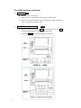
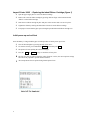
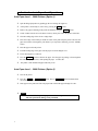
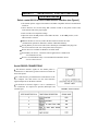
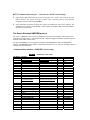
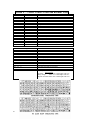
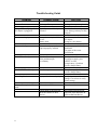
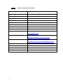
EXTECH DATA SYSTEMS
SERIES 2000i
USER’S GUIDE
VERSION: 07/30/2002
DATE: July 30, 2002
Part Number 2000i-UG
Section 1 … The Printer User Interface
.
Introduction
This guide summarizes the operation and maintenance features of Extech 2000i dot matrix impact printers.
Membrane Switch Functions (see Figure 1)
<ON>
The <ON> switch turns printer power on.
<FEED>
The <FEED> switch advances the paper at a fast rate.
<OFF>
The <OFF> switch turns the printer power off, or pauses and cancels
the print process.
Note: In IrDA mode, press <FEED> momentarily, then <OFF>,
to turn printer power off
<ADVN>*
The <ADVN> switch advances paper at a normal rate.
*Note: This switch function is not present with the MCR version
Front Panel Indicators (see Figure 1)
<ON>
Green
Illuminated when the printer is in operation.
In Serial mode: Extinguishes after 20 seconds when printer defaults
to low power mode to minimize battery consumption.
In IrDA mode: the LED is on steady.
<READY>
Green
In IrDA mode: The LED is illuminated during Infrared communication;
extinguishes after 20 seconds to minimize battery
consumption.
In Serial Mode: the indicator is illuminated when the optional magnetic
card reader is ready for swiping.
Flashes twice before going into Auto Sleep mode when
connected to Host device and the Host RTS output is active.
<CHARGE>
•
Yellow
If illuminated the battery cartridge is accepting charge.
Turns off automatically at the end of the charge cycle.
<LOW PWR> Yellow
If illuminated, the battery cartridge is depleted.
Recharge battery cartridge if LED is on.
DO NOT PRINT IF THE LED IS ILLUMINATED.
2
Front Panel Indicators (continued)
<FAULT>
Red
Indicates printer is out of paper.
Indicates error was encountered while reading the magnetic card.
The FAULT and LOW POWER LED on simultaneously, indicate the printer is
unable to print due to low battery power.
<READY, FAULT, LOW POWER>
Flashing
Indicates printer is paused. Press FEED to resume printing, or press OFF to
cancel the current print and clear any data in print buffer.
Pressing the OFF switch while printing pauses the printer.
3
Section 2 … Charging The Printer Battery
Charging the Battery Cartridge
Insert the battery Cartridge into the printer.
Remove the battery door at the back of the printer, by placing a coin into the slot and
pushing the cover to release the lock; (see Figure 2).
Install the battery cartridge in the battery compartment located at the back of the printer
as shown in Figure 3.
Charge the battery cartridge before operating the printer.
Plug the power adapter into an appropriate wall socket; then plug the power adapter
cord into Power Input Connector at the rear of the printer (see Figure 2). The yellow
Charge light will illuminate, to indicate battery is charging.
The Charge LED turns off when battery cartridge is fully charged. It takes 60 to 90
minutes to fast charge the battery pack.
To insure full charge, printer should not be operated while the battery is charging.
Important notes on charging the battery.
The model 2000i uses 9VDC/1A adapter to recharge the battery pack.
Each time the power adapter is connected to the printer, the battery Fast-charge is initiated.
Before the start of the fast recharge process, the fast-charge controller checks the battery’s
voltage and temperature.
If the battery voltage or the temperature is outside of the fast-charge limits, the charger
defaults to trickle charge
at C/10 or 70mA rate.
Optional external battery
charger is available for
Extech printers, a single
bay fast rate charger and
conditioner and four bay
12 hours trickle charger.
Table 1 – Typical Printer Power Consumption
Refer to the options addendum (TABLE A) for complete list of printer supplies
and accessories and ordering part numbers.
4
.
Section 3 … Loading Printer Paper
.
Impact Printer 2000I - Manually Installing Paper and Ribbon
Open the hinged paper supply
door to load paper or replace
the printer ink cartridge.
To unlock the top hinged
paper cover, hold the printer
with both hands and place
each thumb on the two
locking ribs located below
the grooved sections on the
top cover.
Push the locking ribs in-andup to open the paper door.
FIGURE 4
Loading printer paper
Impact Printer 2000I - Manually Installing Paper
Open the paper supply door by pushing up the locking ribs (figure 4).
Turn on the printer by pressing the ON switch.
Remove any paper remaining in the printer mechanism, using the FEED switch or pulling
the paper in forward direction.
Unroll a leader from the new roll (about 3 inches); do not place roll in the printer at this time.
Place the straight edge of the leader just under the roller in the print head and feed about 3
inches of the new roll of paper into the print head using the FEED switch.
Place paper roll in the printer.
Feed the leading edge of the paper into the slot of the hinged cover.
Lower the hinged cover and lock.
Pull the 3 inches of paper forward against the teeth of the paper tear bar and pull to either side
to tear off the paper.
The printer is then loaded with paper and ready to use.
Caution
Do not REVERSE pull the paper out of the 2000i printer mechanism; this
will cause permanent damage to the print head.
5
Impact Printer 2000I - Replacing the Inked Ribbon Cartridge (figure 1)
Open the paper supply door to access the ribbon cartridge
Remove the worn out ribbon cartridge by pressing with one finger at the location labeled
“EJECT” on the ribbon cartridge.
Insert the new ribbon cartridge in place and press at the extreme ends to secure it in place.
Tighten the ribbon by rotating the ribbed wheel clockwise on the ribbon cartridge.
Feed paper to insure that the paper passes through exposed ribbon and ribbon cartridge case.
Initial power up and self-test
Once the Battery is charged and the paper is loaded perform an initial power up self-test.
Turn off all LED lights by pressing the OFF switch twice.
To start the self-test, press and hold the FEED switch then press ON
The printer will start printing the self-test messages.
Press the
OFF or FEED to stop or cancel the self-test print.
The first few lines of self-test show the printer firmware version, the current printer settings
and a list of any optional or special features installed.
Also sample demo lines are printed using internal printer fonts.
6
Section 4 … Auto Paper Load Operation
f
Auto Paper Load … 2000i Printers (Option 1)
Open the hinged paper door by pushing up the two locking ribs (figure 4).
If the printer is not already on, turn it on by pressing the ON
switch.
Remove any paper remaining in the printer mechanism, using the
FEED switch.
Unroll a leader from the new roll (about 3 inches); do not place roll in the printer at this time.
Trim the leading edge of the roll to a wedge shape.
Place the wedge of the leader just under the roller in the print head; the printer will sense the
paper and advance it through the print head. If you experience difficulty, press the <FEED>
switch.
Place the paper roll in the printer.
Feed the leading edge of the paper into the paper slot on the hinged cover.
Lower the hinged cover and lock.
Press the FEED switch to advance the paper. Tear the paper by pulling it forward against
the teeth of the paper tear bar, while pulling the paper to either side.
The printer is then loaded with paper and ready to use.
Auto Paper Load … 2000i Printers (Option 2)
Turn on the printer
Press the FEED or ADVANCE
will remain on for 60 seconds.
button. The red
ERROR LED is illuminated and
Insert paper to the print head. The auto-paper-load will feed the paper through for 2.00”.
Caution
Do not REVERSE pull the paper out of the 2000i printer mechanism; this
will cause permanent damage to the print head.
7
Section 5 … Serial RS232, IrDA and XMODEM
Communications
Select a serial RS232 or IrDA communication interface (see Figure1)
• The S2000i printers support Serial RS232 and IrDA compatible infrared communication
interfaces.
• These interfaces are selected using DIP switches located on the printer control card,
located on the side of the paper supply.
• Refer to Table 2 for Dipswitch settings.
• Dipswitch #8 in the ON position selects IrDA interface. In the OFF position, serial
RS232 mode is selected.
If RS232 interface is selected, connect the data connector and set the serial
communication parameters: Baud rate, number of Data Bit and Parity.
If using RS232 you also need a cable such as Extech part # 5892RJD9; this plugs into
the serial connector at the rear of the printer shown in Figure 2.
Printer drivers are available for Windows 95/98/NT/2000
For Windows CE devices, PrinterCE control application is available from
www.fieldsoftware.com.
Steven’s Creek PalmPrint Utility is recommended for Palm Pilot devices.
www.stevenscreek.com.
Serial RS232C CONNECTIONS
The RS232C Interface signals for the S2000i printer is
terminated on a 6 PIN RJ25 type data connector located at the
back of the printer.
Six connections are provided from the Serial Interface to the
host computer. The table below lists the Serial Interface
signals and pin outs on the RJ25 connector.
Pin locations are shown in Figure 1.A & 4. A minimum of
two connections are required for operation, RXD-pin3 and
Common-pin1.
8
FIGURE 4 – Serial Connector
RS232 Communication Interface - General notes & DIP switch settings
Eight-position dipswitch, located to one side of the paper roll, is used to select and set the serial
RS232 interface. The printer reads these switches once, on initial power-up. The functions
assigned to each switch are listed in Table 2.
Proper Baud Rate and protocol settings are required to communicate with a host computer. The
standard factory setting is 19,200 BAUD, 8 DATA BITS, NO PARITY BIT, and one STOP BIT,
all switches in off position.
The Extech Extended XMODEM protocol
The Extech XMODEM software option is designed to overcome the unreliability of data transmission
using direct infrared interface. It is intended for host computers equipped with IrDA compatible physical
interface and no IrDA software Stack.
The Extech XMODEM protocol is supported via RS232 (RS-XMODEM) or IrDA (IR-XMODEM)
interface. The XMODEM option and the communication parameters are set using on board dip switches, as
summarized in the table below.
Communication Interface - S2000i DIP switch settings
TABLE 2 - S2000i DIP switch settings
Dip Switch Function
1&2
Baud rate
Standard Baud rate
Special Baud rate
19,200
9,600
4,800
2,400
9,600
4,800
2,400
1,200
SW1
SW2
Off
On
Off
On
Off
Off
On
On
3
No. of data bits
7 Data Bits
8 Data bits
SW3
on
Off
4&5
Parity bit
SW4
SW5
off
on
Off
on
off
off
0n
on
Serial RS232 mode
Alternate mode with SW-8 ON
No Parity
Odd Parity
No Parity
Even Parity
IrDA
Ir-Xmodem
Ir-Direct
RS232-XMODEM
6
Hardware Handshaking
Enable
Disable
SW6
On
Off
7
Clock and Calendar
clock set
SW7
On
8
Communication Interface
RS232
IrDA
SW8
Off
On
9
(OPTIONAL)
Section 6 … Printer Control Codes and Resident Fonts
Character
EOT
BS
HT
LF
VT
FF
CR
SO
SI
XON
AUXON
XOFF
NORM
AUXOFF
CANCEL
ESC
EXTEND
EXTEND OFF
Status All
Status buffer
Hex/Dec
04/04
08/08
09/09
0A/10
0B/11
0C/12
0D/13
0E/14
0F/15
11/17
12/18
13/19
14/20
15/21
18/24
1B/27
1C/28
1D/29
CONTROL ACTION
End Of Text
Back Space
Horizontal Tab
Line Feed
Vertical Tab
Form Feed
Carriage Return
Shift Out – Select double wide print
Shift In – Clear double wide print
Transmitter On.
Printer on.
Printer receiver is off
Return to default 42 column mode
Printer to Host: printer is off
Cancel and reset printer buffer. Default to Standard font.
Escape
Extended print
Extended print off/Normal print
Report Buffer, power timer and battery status
Report number of characters received in buffer
Printer Command Strings
ESC+F+1
(default)
ESC+F+2
ESC+F+3
ESC+1+Null
ESC+0+Null
ESC – G
The graphic character set
ESC - ‘A’
ESC – ‘P’ – alpa
ESC – ‘M’ - ‘000’ - cr
ESC - ‘M’ - ‘nn0’ - cr
ESC – ‘M’ - ‘C’
Printer Function
Standard ASCII and International character set
Hebrew ASCII and Hebrew character set
IBM PC ASCII and IBM PC character set
SELECT 1 DOT SPACING
SELECT 3 DOT SPACING (default)
Select 6-bit graphic print mode
From character '?'(3FH) to TILDA (7EH), CR & LF
Select Text Print Mode. Cancel Graphic mode.
Time and date print and Format control
Disable the power down timer
sets the power down timer to nn seconds
Reset Auto power down to 20 seconds
ESC – ‘M’ - ‘nnm’ - cr
^B
Select optional Magnetic Card reader
Request printer Status Report:
Report Format
Print buffer:
<ESC> <B><4 ASCII digits><CR><LF>
Battery Voltage:
<ESC> <V><4 ASCII digits><CR><LF>
Magnetic card reader:<ESC> <M><4 ASCII digits><CR><LF>
10
Troubleshooting Guide
PROBLEM
POSSIBLE CAUSE
SOLUTION
Printer will not turn on
Discharged Battery
Recharge battery overnight.
Charge LED not lighting when
AC adapter is plugged in.
No AC power or AC adapter
defective
Check AC outlet or adapter
(note: battery pack may be fully
charged)
Battery not charging.
Battery incorrectly installed or
no AC.
Battery dead
Check battery installation and
AC adapter
Change to a new battery
Paper not feeding.
Obstruction in paper path or
paper improperly installed
Check the paper path. Verify
installation
Use paper of the correct
specification
Fault LED on Steady
Print head lever is up
Print mechanism jam
Low Battery
Check print head lever
Check paper supply; press
<FEED> to clear.
Charge battery; if problem
persists, change battery.
Low-BAT LED on Steady
Low battery
Charge battery; if problem
persists, change battery.
Prints illegible characters.
Improper baud rate and parity
Verify the printer and host
settings. Use self-test to verify
printer settings.
Printer will not print in IrDA
mode
Obstruction of IrDA
Clear obstruction.
IrDA mode is not selected
Will not connect to host
device.
DIP switch #8 must be on.
Limit the IrDA baud rate to
9600 on the host device.
.
11
TABLE A - Optional printer parts and supplies
Part Number
Description
757059
2000i paper pack (2.2” / 57.5 mm wide, 1.5” O.D. 5 rolls)
7A100005
2000i Battery Cartridge - 5 Cells – 1400mA
767700
External 4 bays charger for 2000i
767600
Single Bay Fast Charger
157120
Battery charger adapter 2000i 120VAC/9VDC/1A
157220
Battery charger adapter 2000i 220VAC/ 9VDC/1A
S2000i-UG.doc
User’s Guide – 2000I
7A060028
Programmer’s Guide – 2000i
Available from Extech Email
Windows 95/98/NT/2000/ Drivers
[email protected]
Download & register “Extech”
Windows CE print Utility
http://www.fieldsoftware.com/PrinterCE.htm
Download
Palm Pilot print Utility
http://www.stevenscreek.com/pilot/dodownload.html
756996
2000i belt mount case
757995
2000i Rubber boot
756998
Belt Loop System
5892RJD9
Serial Data Cable – RJ to DB9 PC compatible
12
Regulatory Notes
FCC Part 15 Class B
This equipment has been tested and found to comply with the limits for a Class B digital device,
pursuant to Part 15 of the FCC rules. These limits are designed to provide reasonable protection
against harmful interference in a residential installation. This equipment generates, uses and can
radiate radio frequency energy and, if not installed and used in accordance with the instructions,
may cause harmful interference to radio communications. However, there is no guarantee that
interference will not occur in a particular installation. If this equipment does cause harmful
interference to radio or television reception, which can be determined by turning the equipment
off and on, the user is encouraged to try too correct the interference by one or more of the
following measures:
Reorient or relocate the receiving antenna.
Increase the separation between the equipment and the receiver.
Connect the equipment into an outlet on a circuit different from that to which
the receiver is connected.
Consult the dealer or an experienced radio/TV technician for help.
Warranty
This printer is warranted by Extech Data Systems to be free of defects in parts and workmanship
for a period of one year from date of shipment. This warranty does not apply to defects resulting
from action of the user such as misuse, improper wiring, operation outside of specification,
improper maintenance or repair, or unauthorized modification. Extech specifically disclaims any
implied warranties of merchantability or fitness for a specific purpose and will not be liable for
any direct, indirect, special, incidental or consequential damages. Extech’s total liability is limited
to the repair or replacement of the product. The warranty set forth above is inclusive and no other
warranty, whether written or oral is expressed or implied.
Warranty Service
A Return Authorization number must be issued before a unit is returned to Extech for repair. The
customer is responsible for ensuring proper packing to prevent damage in transit. Once a unit has
been properly returned to Extech, it will be repaired (estimates are provided first if the repair cost
is estimated above $100.00) and returned via UPS ground. The customer may elect a faster mode
of transport at their cost.
13