1
EXTECH DATA SYSTEMS
SERIES 2000 + SERIES 3000
DEVELOPER’S GUIDE
VERSION: 4B
DATE: October 2000
Part Number: 7A060028DG
Page 1
Extech Data Systems Celebrates 10 Years
Design and Manufacture Battery Operated Portable Printers
Extech Data Systems, the Portable Printing Division of Extech Instruments, started Engineering
development of a new line of portable instrumentation in 1988, just ten years ago. The first
products from this development, a portable battery operated printer and a portable modem were
introduced in 1989. Designed specifically for the Psion Organiser, this initial foray into the world
of mobile computing proved highly successful. The advent of a low cost, battery operated
portable printer allowed innovative individuals and organizations to develop system solutions for
a variety of interesting applications, including:
§ Duty Gear who developed ‘Ticket Writer,’ a self-contained portable computer system,
programmable that generates parking tickets directly from Extech’s integral printer.
§ Precision Systems who introduced PESTWARE a “revolutionary, cost saving
productivity tool designed to reduce paperwork, handwritten work orders and invoices” for
the Pest Control industry. Using an Extech Comms printer, the system prints work orders and
invoices on the job site.
§ Harvest Computer Consulting who designed Farm Handy™ specifically for agricultural
payrolls using compensation based on a piece rate. The system allows for immediate printing
of receipts for employees.
§ Joint Technologies Ltd. who introduced CoinTRAX© Model 50, a portable coin counting
system that provides fast, accurate accounting of coin and token income from various
machines, companies and locations. CoinTRAX© also provides count verification of tagged
bags, totes, coin rolls and over-the-counter receipts.
Introduction of the mini-serial printer increased the potential for our printers, allowing
integration with virtually any RS232 serial device, including portable computers, pen computers,
vending machines and weighing scales.
§ Streetguard™ Inc. who developed Streetguard VVRS, a hand-held pen computer based
parking ticket writing system that allows writing of the ticket directly on the pen computer
screen and then printing out to the Extech Mini Serial Printer.
In 1991, we introduced a built-in magnetic card reader (MCR) option — available to read either
tracks 1 and 2 or tracks 2 and 3. Both tracks are read and decoded simultaneously. Decoded data
was transferred to the host computer, via the serial port, for verification and consolidation into
receipt form. The completed data is then sent back to the printer for receipt printing. Nowadays,
data transfer is possible through the serial port, bi-directional parallel port or the IrDA port. A
unique two-way communication protocol allows for the decoded data from the magnetic card to
be transmitted to the host computer. Again, a number of interesting applications have been
developed, including:
§ Micros’ Hospitality: visit the Fleet Center in Boston for a Celtics or Bruins game and
enjoy the rapid food system made possible by Micros’ pioneering ordering system. Linking a
hand held pen computer system, local radio network system and an Extech printer with builtPage 2
in magnetic card reader allows fans to order directly from their seat. The order is radioed to
the kitchen, filled and delivered right to the seat. Payment by credit card is made,
authorization obtained over the radio network and on to the next fan! The system is so quick,
additional kitchen space was added!
§ Swedish Railway who introduced “the first computerized conductors in the world”
equipped with a hand held computer and an Extech Mini Serial Printer enabling passengers to
purchase their ticket on the train. A magnetic card reader, integrated right into the printer
means the passenger can pay by credit card as well as cash. The magnetic card reader is set to
read tracks 2 and 3 simultaneously, decode the data and transfer it to the hand held computer.
Extech Data Systems — Ten Years On
EXTECH Data Systems nowadays designs and manufactures battery operated, portable printers
for portable and mobile computing applications. Powerful micro-controllers on highly integrated
circuit boards manage all the features supported by the printers. Custom firmware and printer
designs are provided to meet a wide range of application requirements including special graphics,
simultaneous read of dual track magnetic cards, datalogging, etc. The user may choose impact or
thermal print heads. A full range of communication interfaces is available: serial (RS232),
parallel (unidirectional and bi-directional), infrared IrDA or ASK), and magnetic card reader. All
data interfaces are DOS and Windows compatible. Integration with hand-held computers, PDAs,
pen computers and notebook computers is easily accomplished by OEMs and their system
integrators.
The printers may be operated from a battery pack or from an AC power adapter. Battery
operation provides up to 2 hours of continuous print time - more than sufficient for a normal
shift’s work. A fast charge circuit fully charges the battery in 90 minutes. The high impact plastic
housing encloses easily loaded, single or two-ply paper rolls. Connectors are placed for wearing
comfort and to minimize exposure to the elements. Membrane switches with bright LEDs are
easily reached when worn on a belt or placed on a desk. Typical applications include field sales,
field service, meter reading, route accounting, ticket issuance, and more. Recent product
developments include:
§
Series 2000 (updated impact printer range) and Series 2000T (new thermal printer range).
The new products incorporate a larger paper roll, a new IrDA wireless communication
system, an improved battery charging system, large memory and a new body housing with
built-in belt clip
§
Built-in magnetic card reader version especially suitable for field applications where
payment is preferred at the time of service delivery. Mobile point of sale applications
(EPOS) can also benefit from use of this new printer. Integration with wireless systems
makes credit card authorization possible (EFTPOS)
§
Introduction of alkaline battery powered option for increased portability
§
Introduction of new printers with data logger capability
Page 3
§
Introduction of vehicle mount printers, operating from the vehicle battery, for EFTPOS
systems
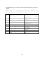
Additionally, the design of our products allows easy modification as needed to satisfy customer
needs. We pride ourselves on responding to specific customer requirements. Over the past four
years the needs of many of our major customers demanded that we develop new variations of
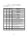
printers for them. Some recent examples include:
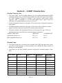
Customer
A
B
C
D
E
F
G
H
I
J
Product
a field sales organization in insurance
Parallel printer with new board and system
design with new communication interface
for Fujitsu pen pad.
a field service operation in retailing
Parallel printer with new interface to work
with Itronix unit
a field sales operation in the food business Parallel printer with Alkaline battery
option
National airline
Serial printer with mcr, operating only
with Alkaline batteries
National railway system
Serial printer with battery monitoring
wireless network provider
MSP III with power from car battery
field service application
MPP III with mcr and bi-directional
parallel interface
aerospace application
MSP (and S 2000) with special date/time
requirement
remote site hospitality
MSP III with RJ II
an OEM needing to satisfy a customer in We developed a Korean font for the S2000
Korea
printer.
Page 4
Section 1 … Preparing the Printer
Introduction
This guide summarizes the programming, operating and maintenance features of the SERIES
2000T, Series 2000i and Series 3000T Extech printers. This section should be included in your
operating guide for the final users of the printer.
Initial preparation of the Printer
§
§
§
§
You must charge the battery cartridge before you can operate the printer.
•
To do this you must install the battery in the printer, or
•
Use a separate battery charger (Part Numbers 767600 or 767700).
•
You will need an Extech (9VDC/1.0A) power adapter normally provided with the printer.
Insert the battery into the printer.
•
To remove the battery door at the back of the printer, place a coin into the slot and
push --- this releases the lock; (see figure 2)
•
Remove the battery door by lifting away from the guide rails.
•
Install the battery cartridge in the battery compartment located at the back of the
printer (as shown in Figure 2).
If the battery has not been previously charged in an external battery charger, you will need
to charge it overnight in the printer.
•
Place the power adapter into an appropriate wall socket; then plug the power adapter
cord into the connector at the rear of the printer (see Figure 3). The yellow <Charge>
light will illuminate.
•
Leave the battery on charge for 12 hours.
Select a serial communication interface RS232 or IrDA. (see figure 1)
•
Dip switch #8 in the “on” position selects IrDA interface. In the “off” position, RS232 is
selected.
•
If RS232 interface is selected, connect the data connector and set the serial
communication parameters: Baud rate, Data Bit and Parity.
•
If using RS232 you also need a cable such as Extech’s part # 5892RJD9; this plugs into
the serial connector at the rear of the printer (Figure 3).
•
If interfacing to a PC, Set MS-DOS and Windows variables.
Initial power up and self-test
§
To start the self-test, press and hold the <FEED> switch then press <ON>.
•
§
The printer will print a self-test.
Press the <OFF> to turn off the printer and stop the self-test.
Page 5
§
Press the <ON> switch to turn on the printer.
Manually Installing Paper (figure 4) … Thermal Printers
§
To unlock the top hinged cover, place each thumb on the grooved sections indicated in
the figure at the rear of the cover. Press the two locking ribs located at the rear of the
printer to release the first lock; raise the hinged cover to open. Press on the two locking
arms to allow the cover to fully open and provide access to the paper area.
§
Release the print head pressure by lifting the lever located next to the paper advance knob
on the right side of the printer.
§
Unroll a leader from the new roll (about 3 inches); do not place roll in the printer at this
time.
§
Trim the leading edge of the roll to a wedge shape as illustrated.
§
Place the edge of the leader just under the roller in the print head; manually feed the paper
into the print head until it appears exiting at the top of the roller.
§
Push the print head lever down to secure the paper in position.
§
Place roll in the printer.
§
Advance about 4 inches of paper by rotating the paper advance knob.
§
Feed the leading edge of the paper into the slot of the hinged cover
§
Lower the hinged cover and press to lock.
§
Pull the 4 inches of paper forward against the teeth of the paper tear bar and pull to either
side to tear off the paper.
§
The printer is then loaded with paper and ready to use.
§
Caution:
•
To manually remove paper out of the printer mechanism, lift the lever located at the right
hand side of the printer mechanism and remove paper.
Auto Paper Load (figure 4) … Thermal Printers
§
To unlock the top hinged cover, place each thumb on the grooved sections indicated in
the figure at the rear of the cover. Press the two locking ribs located at the rear of the
printer to release the first lock; raise the hinged cover to open. Press on the two locking
arms to allow the cover to fully open and provide access to the paper area.
§
If the printer is not already on, turn it on by pressing the <ON> switch.
§
Remove any paper remaining in the printer mechanism, using the <FEED> switch.
§
Unroll a leader from the new roll (about 3 inches); do not place roll in the printer at this
time.
§
Trim the leading edge of the roll to a wedge shape.
Page 6
§
Place the wedge of the leader just under the roller in the print-head; the printer will sense
the paper and advance it through the print-head. If you experience difficulty, press the
<FEED> switch.
§
Place roll in the printer.
§
Feed the leading edge of the paper into the slot of the hinged cover
§
Lower the hinged cover and lock.
§
Pull the 4 inches of paper forward against the teeth of the paper tear bar and pull to either
side to tear off the paper.
§
The printer is then loaded with paper and ready to use.
§
Caution:
•
To manually remove paper out of the printer mechanism, lift the lever located at the
right hand side of the printer mechanism and remove paper.
•
Similarly, to manually insert paper, lift the lever, tear the leader into a triangle shape,
insert the lead under the roller and then use the paper advance knob to advance the
paper until it appears exiting from the printer mechanism.
•
When finished, push the lever back down and close the paper cover.
Installing Paper (figure 4) … Impact Printers
§
To unlock the top hinged cover. Place each thumb on the grooved sections indicated in
the figure at the rear of the cover. Press the two locking ribs located at the rear of the
printer to release the first lock; raise the hinged cover to open. Press on the two locking
arms to allow the cover to fully open and provide access to the paper area.
§
If the printer is not already on, turn it on by pressing the <ON> switch.
§
Remove any paper remaining in the printer mechanism, using the <FEED> switch.
§
Unroll a leader from the new roll (about 3 inches); do not place roll in the printer at this
time.
§
Place the straight edge of the leader just under the roller in the print-head and feed about
3 inches of the new roll of paper into the print-head using the <FEED> switch.
§
Place paper roll in the printer.
§
Feed the leading edge of the paper into the slot of the hinged cover
§
Lower the hinged cover and lock.
§
Pull the 3 inches of paper forward against the teeth of the paper tear bar and pull to either
side to tear off the paper.
§
The printer is then loaded with paper and ready to use.
§
Caution:
•
Do not REVERSE pull paper out of the printer mechanism; this will cause damage to the
print head.
Page 7
Installing Ribbon (figure 1) … Impact Printers
§
Unlock and raise the top hinged cover as described above. Remove the worn out ribbon
by pressing with one finger at the location labeled “EJECT” on the ribbon cartridge.
§
Insert the new ribbon in place and press at the extreme ends of the ribbon cartridge to
secure it in place. With your thumb, tighten the ribbon, by rotating clockwise, the ribbed
wheel located on the front of the ribbon cartridge.
§
Feed paper to insure that the paper passes through exposed ribbon and ribbon cartridge
case.
Membrane Switch Functions (see figure 1)
§ <ON>
The <ON> switch turns printer power on.
§ <FEED>
The <FEED> switch advances the paper at a fast rate.
§ <OFF>
The <OFF> switch turns the printer power off.
Note: In IrDA mode, press <FEED> momentarily, then <OFF>.
§ <ADVN>*
The <ADVN> switch advances paper at a normal rate.
(* This switch function is not present with the MCR version)
Front Panel Indicators (see figure 1)
§ <ON>
Green
•
Illuminated when the printer is in operation.
•
In Serial mode, extinguishes after 20 seconds before going into Auto Sleep mode to
minimize battery consumption.
•
In IrDA mode, on steady.
§ <READY>
Green
•
In IrDA mode, is illuminated during Infrared communication; extinguishes after 20
seconds to minimize battery consumption.
•
In Serial mode is illuminated when the optional Magnetic Card Reader is ready for
swiping.
•
Flashes twice before going into Auto Sleep mode when connected to PC.
§ <Charge>
Yellow
•
If illuminated the battery cartridge is accepting charge.
•
Turns off automatically at the end of the charge cycle.
§ <LOW PWR>
Yellow
•
If illuminated the battery cartridge is depleted.
•
Recharge battery cartridge if LED is on.
Page 8
§ <FAULT>
Red
Ÿ Indicates printer paper out.
Ÿ Indicates print head lever is up.
Ÿ Indicates incorrect read with magnetic card reader.
Ÿ
§
Indicates printing with low power (printing not possible).
<READY, FAULT, LOW POWER>
Ÿ
Flashing
Indicates printer is paused; to continue printing current receipt, press <FEED> or to clear
print buffer press <OFF>.
Page 9
Section 2 … Serial Communications
RS 232 Communication Interface (Standard)
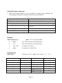
§
Eight position dip switch, located to the left of the paper roll, is used to select and set the
serial RS232 interface. The printer reads these switches once on initial power-up (see
below).
§
Proper Baud Rate and protocol settings are required to communicate with a host
computer. The standard factory setting is 19,200 BAUD, 8 DATA BITS, NO PARITY
BIT, and one STOP BIT, all switches in off position. To make changes use the table
below:
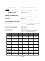
Dip Switch
Function
1&2
Baud rate
SW1
SW2
19,200
off
off
9,600
on
off
4,800
off
on
2,400
on
on
No. of data bits
SW3
7 Data Bits
on
8 Data bits
off
Parity bit
SW4
SW5
No Parity
off
off
Odd Parity
on
off
Even Parity
on
on
Hardware Handshaking
SW6
enable
on
disable
off
Clock and Calendar
SW7
clock set
on
Communication Interface
SW8
RS232
off
IrDA
on
3
4&5
6
7
8
Page 10
RS 232 Communication Interface (Special / Impact Only)
§
The standard factory setting for this version is 9,600 BAUD, 8 DATA BITS, NO
PARITY BIT, and one STOP BIT, all switches in off position. To make changes use the
table below:
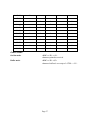
Dip Switch
Function
1&2
Baud rate
SW1
SW2
9,600
off
off
4,800
on
off
2,400
off
on
1,200
on
on
No. of data bits
SW3
7 Data Bits
on
8 Data bits
off
Parity bit
SW4
SW5
No Parity
off
off
Odd Parity
on
off
Even Parity
on
on
Hardware Handshaking
SW6
enable
on
disable
off
Clock and Calendar
SW7
clock set
on
Communication Interface
SW8
RS232
off
IrDA
on
3
4&5
6
7
8
Page 11
RS232C Connections
§
The RS232C Interface signals for the S2000T Series printers are terminated on a 6 PIN
RJ type data connector located at the back of the printer (Figure 3).
§
Six connections are provided from the Serial Interface to the host computer for proper
operation of this option.
§
The table below lists the Serial Interface signals and pinouts on the RJ connector.
§
A minimum of two connections are required for operation, RXD-pin3 and Common-pin1.
RJ
CONNECTOR PIN #
3
2
6
4
1, 5
FUNCTIONAL
DESCRIPTION
RS232 from Host (INPUT)
RS232 from Printer (OUTPUT)
Request to send from Host (INPUT)
Clear to send from Printer (OUTPUT)
Logic common
RS232C Technical Specifications
§
RS232C technical specifications are as follows:
DATA TRANSFER RATE:
2400 Through 19200 baud
WORD LENGTH:
1 Start bit
7 Or 8 Data bits
1 Or 2 Stops bits
PARITY BIT:
None, Odd or even
SIGNAL LEVELS:
Mark or Logical
1 = -3 to -15VDC
Space or Logical
0 = +3 to +15VDC
HANDSHAKING:
§
RTS/CTS or XON/XOFF
Caution:
•
In one version of the Impact Printer, the baud rate is from 1200 through 9600.
Page 12
SIGNAL
NAME
RXD
TXD
RTS
CTS
COM
SERIAL IrDA Communication Interface
§
This section summarizes the operating features of the Extech S2000T printer series with
built in Infrared Data Receiver Interface (IrDA)
§
The IrDA Interface is designed for reception of serial data and no interconnecting cables
are required for data transfer. It conforms and exceeds Infrared Data Association protocol
specifications for secondary station, as specified in IrDA-1 standard.
§
Three layers of the IrDA protocol specifications are supported:
•
the IrDA Serial Infrared Physical Layer
•
the Link Access Protocol (IRLAP) and
•
the Link Management Protocol (IRLMP)
§
Additionally, we have implemented IRComm 3-wire raw as a file transfer protocol for
communication of decoded magnetic card data from the printer to the host computer (see
Section X)
§
Dip switch #8 ON, selects the IrDA interface. The Green <READY> is illuminated on
power-up if the IrDA interface is selected.
§
The table below lists the IrDA interface specification.
Protocol Compatibility:
Carrier:
IrDA Version 1 IRLAP and IRLMP compatible.
Infrared light
IrDA physical layer compatible
peak wavelength 850 to 1050 nm
Communication Distance:
Transmission Speed:
0 cm to 100 cm
Default to 19200
negotiable 2400 to 19.2k
Parity bit:
Data bit:
Stop bit:
Error check:
none
8 bits
1
CRC
Page 13
Section 3 ... Battery
Battery Recharging Operation
§
The Extech Printers features an internal fast battery recharge system. This system is
designed to fast charge the battery cartridges in 90 minutes using 120V/9VDC/1.0A
power adapter (PN# 152120). This adapter is designed for North American use. Both
220V (PN# 152320) and 240V (PN# 152340) versions are available for international use.
§
The battery voltage, temperature and maximum charge time are monitored during battery
recharge cycle.
Initiating Fast-Charge
§
The battery Fast-charge is initiated, when the power adapter is applied to the printer.
§
The battery's voltage and temperature are checked by the fast-charge controller before the
start of the fast recharge process.
§
If the battery voltage or the temperature is outside of the fast-charge limits, the charger
defaults to trickle charge at C/64 rate.
§
If the battery voltage and the temperature are valid the yellow <CHARGE> LED is
illuminated and the fast-charge at the 1C rate is initiated. The battery temperature and
voltage limits are as follows:
Ÿ
Temperature:
less then 50C
Ÿ
Voltage:
greater than 2 VDC or less than 7 VDC.
Fast-Charge Termination
§
The controller continues the fast-charge process until any one of the following charge
termination conditions are encountered:
Ÿ
Peak battery pack voltage is detected.
Ÿ
Recharger Timer time-out (90 minutes).
Ÿ
Battery temperature greater then 50C
§
The yellow fast <CHARGE> LED is turned off at the end of the fast charge cycle and a 5
minute Top-off charge cycle is initiated. The Top-off charge cycle insures full battery
charge.
§
Pulsed trickle charge cycle follows the Top-off cycle. The battery is trickle charged at
C/64 rate.
Page 14
Section 4 ... Control and Character Set
Control Characters
§
The printer has a set of commands which provide control of printer functions. The printer
also provides response commands informing the user of the printer status.
§
In this section, the recognized control characters and the corresponding printer actions are
summarized below:
Character
EOT
Con
^D
Hex/Dec
04/04
BS
^H
08/08
HT
^I
09/09
LF
^J
0A/10
VT
^K
0B/11
FF
^L
0C/12
CR
^M
0D/13
SO
^N
0E/14
SI
^O
0F/15
XON
^Q
11/17
AUXON
^R
12/18
CONTROL ACTION
End Of Text
Printer sends an EOT character when buffer is empty;
tells the host that printer is in idle mode.
Back Space
remove previous character in print buffer.
Horizontal Tab
Tab to 5,9,13,17,21,25,29,33,37 or to the beginning of
next line.
Line Feed
Advance to beginning of next line.
Vertical Tab
Advance 5 lines.
Form Feed
Advance 10 lines.
Carriage Return
Advance to beginning of next line.
clears double width or extended print pending.
Shift Out
All characters are printed in double width (10x7)
Shift In
All characters are printed in normal width (5x7).
Transmitter On
Printer to Host: Ready to receive data.
Host to printer: The host is ready to accept data.
Print on
Printer to Host: Print is on line.
Transmitted after initial power up or clearing of printer
jam.
Page 15
Character
XOFF
Control
^S
Hex/Dec
13/19
NORM
AUXOFF
^T
^U
14/20
15/21
CANCEL
^X
18/24
ESC
^[
1B/27
EXTEND
^\
1C/28
EXTEND
OFF
^]
1D/29
CONTROL ACTION
Printer receiver is off
Printer to Host: Print Buffer is full.
Host to Printer: Host transmitter off.
Return to normal print
Printer to Host: printer is off
transmitted to host before power down or paper out
Cancel and reset printer
If received, print buffer is reset and printer placed in
initial power-up default settings.
Escape
Escape character precedes graphics and printer
operating modes. Refer to escape command section.
Extended print
All characters following this command are printed
double high (5x14).
Extended print off/Normal print
All characters following this command are printed
normal size (5x7)
Page 16
Section 5 ... S 2000i Character Sets
Resident Character Sets (S2000i)
§
There are 3 resident fonts for the 2000i.
CHARACTER NAME
MSP FONT
International character set (Standard)
Hebrew character set
IBM compatible character set
ESC+F+1
ESC+F+2
ESC+F+3
§
The characters are formed using a 5x7 matrix. The first 127 entries in the font table are
ASCII characters. Characters 0 through 31 are ASCII printer control characters, while 32
through 127 are the 96 ASCII alpha numeric upper and lower case characters
§
The alternate (extended) characters for each font type are from 128 through 255
§
The printer defaults to Standard font on initial power up or upon receiving the CANCEL
command (^X,18H,24).
Character Size
§
Four character sizes can be selected through the communication interface, by sending
control characters to the printer
Character Size
Normal
Expanded (Double Wide)
Extended (Double Height)
Large (double wide and double height)
Dot matrix size
5x7
10x7
5x14
10x14
Normal Character
§
The Normal characters are formed using a 5x7 dot matrix. The printer defaults to 5x7
matrix Normal character size upon initial power-up.
Expanded Character
§
Expanded size or double wide characters are formed by using 10x7 dot matrix.
§
Expanded print is selected by sending the EXPAND character command (0E/14) to the
printer, all succeeding characters are printed in Expanded form. Sending the EXPAND
OFF character (0F/15) or Carriage Return resets the Expanded print to normal print.
Extended Character
§
The Extended or double height characters are formed by using a 5x14 dot matrix.
§
Extended Print can be selected through the communication interface by sending the
EXTEND command (1C/28) character. EXTEND (1D/29) or Carriage return resets the
Extended print to normal print.
Large Character
Page 17
§
The Large characters are formed by using a 10x14 dot matrix. Large character print is
selected if both Expanded and Extended print is selected. To reset large print to normal
print, Expanded and Extended prints must be disabled or Carriage return sent to printer.
Dot Addressable Graphics
§
The SERIES 2000i can print special symbols, graphs and characters if operated in the
Dot Addressable Graphics mode.
§
In the Dot Addressable Graphics mode of operation, the printer prints one dot line at a
time. Each horizontal dot line is made out of (1x6) dot cells, and the total number of dot
cells per line is the same as the maximum number of columns on the printer.
§
Each dot in a (1x6) dot cell can be turned ON or OFF by sending specific ASCII
characters.
§
The graphics mode is invoked by sending ASCII characters 'ESC' (1B/27) followed by
'G'. Dot line printing starts upon receiving enough dot cells to complete a dot line, or
ASCII 'CR' (0DH) or ASCII 'LF' (0AH)
§
The graphics mode is terminated by sending ASCII characters 'ESC', followed by 'A'.
Graphic Character Set
§
The graphic character set extends from the character '?'(3FH) to TILDA (7EH). Bits 1
through 6 of the characters received are used to turn ON or OFF the dots in a dot cell.
§
If a bit is set (=1), a dot is enabled, otherwise the dot is disabled.
§
For example for ASCII '?' (3FH or 00111111B), bits 1 through 6 are set. Sending
consecutive '?'s will form a one dot solid line across the paper.
Page 18
Section 6 ... S 2000T Character Sets
Resident Character Sets
§
The Series 2000T has two resident character sets, the standard international and IBM
compatible character sets. For both resident character sets, the lower 128 bit values follow
the ASCII standard. Characters 0 through 31 are reserved ASCII printer control
characters, while 32 through 127, are the ASCII alpha numeric upper lower case
characters. The extended characters are from 128 to 255.
§
For the international character set, the upper 128 bit values code a collection of characters
and symbols.
§
The IBM compatible character set, the upper 128 bit values code a collection of block
graphic characters and special characters for drawing frames and boxes.
§
The printer defaults to the international character set on initial power up. To select an
alternate character set the following command strings are recognized.
CHARACTER NAME
MSP FONT
COURIER FONT
International character set
ESC+F+1
ESC+6
IBM compatible character set
ESC+F+2
ESC+7
Resident Fonts
§
The S2000T printer has two built-in user selectable fonts. MSP Dot-matrix and Courier
type fonts. For each font type, several font typefaces are available, this feature enables 24
through 64 column printing.
§
Listed below are the fonts installed, properties and typeface command strings to select
them.
FONT NAME
PITCH
COLUMNS PER CHARACTER
LINE
SIZE (WxH)
SOFTWARE
COMMAND
32 cpi
64
6x16
ESC+F+1 or
ESC+F+2
ESC+F+9
24 cpi
48
8x16
ESC+F+8
21 cpi
42
10x16
ESC+F+7
20 cpi
40
10x16
ESC+F+6
16 cpi
32
12x16
ESC+F+5
12 cpi
24
16x16
ESC+F+4
MSP
COURIER
ESC+F+6 or
ESC+F+7
Page 19
24 cpi bold
48
8x21
ESC+F+7
ESC+k+5
21 cpi bold
42
9x21
ESC+k+4
19 cpi normal
38
10x21
ESC+k+3
16 cpi normal
32
12x21
ESC+k+2
12 cpi normal
24
16x21
ESC+k+1
12 cpi bold
24
16x21
ESC+k+0
§
Both fonts are monospaced, meaning for each character pitch selected (cpi) all the
characters are exactly the same width, making page layout easy to control. The MSP
compatible dot matrix font are based on a single 6x16 font table. The printer modifies this
table to yield various widths and weights.
§
Four different font tables are used to generate the courier font typefaces. On initial power
up, the printer defaults to 42 column, 21 cpi courier typeface. For the Courier normal
characters, the individual lines or strokes of each character are finer, giving a more airy
feel to the typeface. Courier bold characters have a heavier or thicker line width, putting
more emphasis in the text.
6-Bit Dot Addressable Graphics commands:
§
The printer will operate in 6-Bit Dot Addressable Graphics mode on receiving the Esc-G
graphic command. While in this mode the printer prints one dot line at a time on receipt
of 64 graphic characters or LF command. The LF command advances the paper by one
dot line.
§
Each horizontal graphic dot is made from 1x6 dot cells; the total number of dot cells per
line is 64, corresponding to the 384 total dots per line capacity. Each dot in a dot cell can
be turned on or off by sending specific ASCII characters. For example, #F hex will
energize all dots, while 40 hex de-energizes all the dots.
Select 6 Bit Addressable Graphic Mode:
<ESC> <G>
Graphic Character set:
From 03F-7E Hex using bits 0-5
Select Text Mode:
<ESC> <A>
Perform single .25 dot line feed:
<ESC> <J> <n> or <LF> or <CR>
Page 20
Section 7 ... Operating in MS-DOS World
For proper operation of the S2000T printers in the DOS environment, the following are required:
FOR SERIES 2000T - Serial Printer Version
§
Use DOS print command to print, or Write Direct to printer port.
§
Set the PC's communication baud using DOS MODE command: Printer and PC baud rate
and parity have to match.
Ÿ
§
Redirect PC's serial (COM) port to parallel (LPT)
Ÿ
§
MODE com1:19200,n,8,1
MODE lpt1:=com1:
Set the printer port for infinite retry using the DOS MODE command.
Ÿ
MODE LPT1:,,P
FOR SERIES 2000T - IrDA Printer Version
§
To operate the IrDA interface in MS-DOS environment, an IrDA device driver is
required. IrDA.SYS device driver is available from Extech.
§
Install the file IrDA.SYS to the boot fixed drive.
§
Next, modify the CONFIG.SYS file to include IrDA.SYS as one of the device drivers.
For example: DEVICE = C:\IrDA.SYS COM1 IRQ4 ADDR3F8 ; where C:\ is the path of
where you copied IrDA.SYS to, COM1 is the comport you choose, IRQ4 is the interrupt
request of that com port, and ADDR3F8 is the base address of that com port.
§
Finally, modify the AUTOEXEC.BAT file to include a command to reroute one of the
line printers to the com port, for example:
Ÿ
§
MODE LPT1:=COM1:
Re-boot DOS so that the modified CONFIG.SYS and AUTOEXEC.BAT take effect.
From that point on, anything you send to the rerouted line printer will go through the
IrDA.SYS driver.
Operating in Windows
§
To insure proper operation of the SERIES 2000 parallel version, in windows environment
the following are required.
§
Select Generic/text only printer driver.
§
Use Windows printer manager.
§
For the SERIES 2000 serial version, set the PC's serial port (COM1) baud rate and parity
to match printer.
§
Use printer Self-Test to verify baud rate and parity setting.
Page 21
Section 8 ... Supervised Mode Operation
§
The S2000T printers can be operated in a supervised mode. A single byte supervision
command <0x02> (^B), allows polling the status of the printer.
§
The printer transmits the three types of status strings upon receiving the supervision
request command byte:
•
Print buffer status:
<ESC> <B>
•
Battery Voltage status:
<ESC> <V> <4 ASCII digits><CR><LF>
•
MCR status:
<ESC> <M><4 ASCII digits><CR><LF>
<4 ASCII digits><CR><LF>
§
The four ASCII digits report the number of characters in print buffer, current battery
voltage level and Magnetic Card Reader (MCR) status. These digits are in "converted
hexadecimal" format. To reconvert these digits to hexadecimal form, subtract <0x30>
from each digit received.
§
In general, the printer can be polled as often as needed. The poll response is transmitted
as one complete transaction with no XON/XOFF, ^D or AuxOff in the middle of
response.
§
The examples below illustrate the supervisory response strings.
Print buffer status
§
For Example if <0x04D2> characters are in the print buffer, the following string is
returned upon receiving a <0x02> poll command.
<0x1B> <0x42>
<0x30> <0x34> <0x3D> <0x32>
<ESC> <B>
----<4 ASCII digits>----
<0x0D> <0x0A>
<CR>
<LF>
Magnetic card reader status
§
For Example, if the following Magnetic card read command is issued (esc-M-9-9-1-CRLF), the following is returned upon receiving a <0x02> poll command.
<0x1B> <0x4D>
<0x30> <0x39> <0x39> <0x31>
<0x0D> <0x0A>
<ESC> <M>
<time out>
<CR>
<track>
Page 22
<LF>
Printer battery level status
§
For Example, if the printer battery voltage is at 6.58 volts the following battery status
string is returned upon receiving a <0x02> poll command.
<0x1B> <0x4D> <0x00> <0x36> <0x35> <0x38>
§
<0x0D> <0x0A>
The internal battery voltage can vary from 5.00 (depleted) to 7.25 (full charge) volts.
Page 23
Section 9 ... Auto Power Down Feature
§
In order to conserve battery life the S2000T printer features a auto power down timer.
The power down timer defaults to 20 seconds on initial power up.
§
The auto power down timer can be set by sending recognized command string or disabled
by activating the <RTS> input line or setting the auto power down timer to zero.
§
The auto power down command string:
ESC
M
n
27
77
Disable timer:
27
77
48
Set to 99 seconds:
27
77
57
n
0
CR
48
13
48
48
13
57
48
13
2 digit ASCII 48 thru 57
§
The first two characters "ESC" and "M" are command header characters. The next two
digits ASCII "01" through "99" sets the time-out in seconds, while the last two characters
are the command terminator characters.
§
Sending ESC-C resets the auto timer to initial power up default setting of 20 seconds.
Page 24
Section 10 ... Firmware V1.09 (S2000T)
Control Characters
§
Control characters are from 01 through 31.
Character
EOT
Control
^D
Hex/Dec.
04/04
BS
^H
08/08
HT
^I
09/09
LF
^J
0A/10
VT
^K
0B/11
FF
^L
0C/12
CR
^M
0D/13
SO
^N
0E/14
SI
^O
0F/15
XON
^Q
11/17
AUXON
^R
12/18
XOFF
^S
13/19
NORM
AUXOFF
^T
^U
14/20
15/21
CONTROL ACTION
End Of Text
Printer sends an EOT character when buffer is empty.
This is used to tell the host that printer is in idle mode.
Back Space
Remove previous character in print buffer.
Horizontal Tab
Tab to 5,9,13,17,21,25,29,33,37,41 or to the beginning
of next line.
Line Feed
Advance to beginning of next line.
Vertical Tab
Advance 5 lines.
Form Feed
Advance 10 lines.
Carriage Return
Advance to beginning of next line.
Clears double width or extended print pending.
Shift Out
All characters are printed in double width (10x7).
Shift In
All characters are printed in normal width (5x7).
Transmitter On
Printer to Host: Ready to receive data.
Host to printer: The host is ready to accept data.
Print on
Printer to Host: Print is on line.
Transmitted after initial power up or clearing of printer
jam.
Printer receiver is off
Printer to Host: Print Buffer is full.
Host to Printer: Host transmitter off.
Return to normal print
Printer to Host: printer is off
Transmitted to host before power down or paper out
Page 25
Character
CANCEL
Control
^X
Hex/Dec
18/24
ESC
^[
1B/27
EXTEND
^\
1C/28
EXTEND
OFF
^]
1D/29
CONTROL ACTION
Cancel and reset printer
If received, print buffer is reset and printer placed in
initial power-up default settings.
Escape
Escape character precedes graphics and printer
operating modes. Refer to escape command section.
Extended print
All characters following this command are printed
double high (5x14).
Extended print off/Normal print
All characters following this command are printed
normal size (5x7)
Auto Paper Load
§
Procedure A.
x Turn on the printer
x Lift up the head lever. The red ERROR led will remain on for 60 seconds.
x Insert paper to the print head and lower the lever. The auto-paper-load will feed the paper through
for 2.00".
§
Procedure B.
x Turn on the printer
x Press the FEED/ADVANCE button. The red ERROR led will remain on for 60 seconds.
x Insert paper to the print head. The auto-paper-load will feed the paper through for 2.00".
Page 26
Issuing Escape Commands
§
Many 2000T printer properties may be modified by issuing escape commands. The
following pages detail these commands using conventions detailed here:
Symbol
Purpose
<CTRL>
The next character is a control character
<ESC>, <CR>, <LF>…
Control characters
<‘A’>, <‘P’>, <‘Q’>…
Single quotation marks (‘’) denote constant ASCII
characters.
<n>, <L>…
Italics denote variable bytes in control string.
0x00, 0xAB, 0x1F…
Hexadecimal representation of a number.
Example:
8 Bit Graphic Line(s)
<ESC> <‘V’> <n1> <n2> <data>
•
<ESC>
is the ASCII character 0x1B hexadecimal.
•
<‘V’>
is the ASCII character 0x56 hexadecimal.
•
<n1>, <n2>
are single byte variables.
•
<data>
is a sequence of variable data.
Font Selection
MSP FONTS
ASCII range 32-255 <ESC> <‘F’> <n> (n = {‘4’ .. ‘9’})
Number of columns
Matrix size
Command
Character pitch
64
6 x 16
<ESC> <‘F’> <‘9’>
32 CPI
48
8 x 16
<ESC> <‘F’> <‘8’>
24 CPI
42
9 x 16
<ESC> <‘F’> <‘7’>
21 CPI
40
9 x 16
<ESC> <‘F’> <‘6’>
20 CPI
32
12 x 16
<ESC> <‘F’> <‘5’>
16 CPI
24
16 x 16
<ESC> <‘F’> <‘4’>
12 CPI
Page 27
COURIER FONTS
ASCII range 32-255 <ESC><‘k’><n> (n = {‘0’ to ‘5’})
Number of columns
Matrix size
Command
Character pitch
48
8 x 22
<ESC> <‘k’> <‘5’>
25 CPI
42
9 x 22
<ESC> <‘k’> <‘4’>
23 CPI
38
10 x 22
<ESC> <‘k’> <‘3’>
20 CPI
32
12 x 22
<ESC> <‘k’> <‘2’>
17 CPI
24
16 x 22
<ESC> <‘k’> <‘1’>
13 CPI
24
16 x 22
<ESC> <‘k’> <‘0’>
13 CPI BOLD
Print Contrast Adjust Commands
<ESC> <‘P’> <n>
(n = {‘0’ .. ‘9’}
‘0’: most contrast
‘9’: least contrast
6-Bit Dot Addressable Graphics
The printer will operate in 6-Bit Dot Addressable Graphics mode on receiving the Esc-G graphic
command. While in this mode the printer prints one dot line at a time on receipt of 64 graphic
characters or LF command. The LF command advances the paper by one (0.25mm) dot line.
Each horizontal graphic dot is made from 1x6 dot cells; the total number of dot cells per line is
64, corresponding to the 384 total dots per line capacity. Each dot in a dot cell can be turned on
or off by sending specific ASCII characters. For example, 0x3F hex will energize all dots, while
0x40 hex de-energizes all the dots.
Select 6 Bit Addressable Graphic Mode:
<ESC> <‘G’>
Graphic Character set:
From 03F-7E Hex using bits 0-5
Select Text Mode:
<ESC> <‘A’>
Perform n .25mm dot line feed:
<ESC> <‘J’> <n>
Perform single .25mm dot line feed:
<LF> or <CR>
Page 28
8-Bit Dot Addressable Graphics
8 Bit Graphic Line(s):
<ESC> <‘V’> <n1> <n2> <data>
n1: 8 bit integer indicating the number of
48 byte graphic lines to be received.
n2: ignored.
Graphic Character set:
From 00-FF Hex using bits 0-7
(Bit seven left)
Perform n <.125mm> dot line feed:
<ESC> <‘J’> <n>
Supervisory commands
Command:
Printer status request:
<CTRL> <‘B’>
Response:
Print buffer status:
<ESC> <‘B’> <4 ASCII digits> <CR> <LF>
MCR status:
<ESC> <‘M’> <4 ASCII digits> <CR> <LF>
Command:
Battery status request:
<CTRL> <‘V’>
Response:
Print buffer status:
<ESC> <‘B’> <4 ASCII digits> <CR> <LF>
Battery Voltage status:
<ESC> <‘V’> <4 ASCII digits> <CR> <LF>
Command:
Power down:
<ESC> <‘M’> <2 ASCII digits> <‘0’> <CR>
Print Battery voltage:
<ESC> <‘P’> <‘^’>
Magnetic Card Reader (MCR)
Enable MCR:
<ESC> <‘M’> <2 ASCII digits> <n> <CR>
Disable MCR:
<ESC> <‘C’>
(For details of MCR see Section 14)
Clock/Calendar and Line Counter commands
Set Clock/Calendar:
<ESC> <‘P’> <‘s’> <ASCII Time and Date String>
< 12:30:00 12/12/98 >
Enable Auto Clock/calendar print:
<ESC> <‘P’> <‘>’>
Disable Auto Clock/calendar print:
<ESC> <P> <‘<’>
Page 29
Reset Line Counter:
<ESC> <‘P’> <‘?’>
Print Clock/calendar:
<ESC> <‘P’> <ASCII Letter for print format>
(‘@’, ‘A’ ..‘Y’. Using bits 0 through 5)
Character
0x40 (‘@’)
0x41 (‘A’)
Hours/Minutes
X
Seconds
X
0x42 (‘B’)
X
X
Month/Days
X
X
Years
X
X
X
0x43 (‘C’)
0x44 (‘D’)
X
X
X
0x45 (‘E’)
0x46 (‘F’)
Line Count
X
X
X
X
X
X
X
X
X
X
X
X
X
X
0x47 (‘G’)
0x48 (‘H’)
X
0x49 (‘I’)
0x4A (‘J’)
X
X
0x4B (‘K’)
0x4C (‘L’)
X
0x4D (‘M’)
0x4E (‘N’)
X
X
X
X
X
X
X
0x4F (‘O’)
0x50 (‘P’)
X
X
0x51 (‘Q’)
0x52 (‘R’)
X
X
X
X
X
X
X
0x53 (‘S’)
0x54 (‘T’)
X
X
X
X
0x55 (‘U’)
0x56 (‘V’)
X
X
X
0x57 (‘W’)
0x58 (‘X’)
X
0x59 (‘Y’)
Page 30
X
X
X
X
Printer Mode
On-line mode:
<ESC> <‘P’> < ‘#’>
Characters printed as received.
Buffer mode:
<ESC> <‘P’> <‘$’>
Characters buffered until receipt of <CTRL> <‘D’>.
Future Features
Font Download
Load a character:
<ESC> <‘D’> <n1> <n2> <data>
n1:
Bank to save the character in {0x00,0x01,0x02}
n2:
character code {32 .. 255}
data: 16 x 23 bit character matrix
Use a downloaded font:
n1:
<ESC> <‘d’> <n1>
Font to print {0 - 6} (see Courier font)
Logo Download
Begin "recording" a graphic image:
<ESC> <‘L’> <‘$’>
Stop "recording" a graphic image:
<ESC> <‘L’> <‘#’>
Print recorded image:
<ESC> <‘L’> <‘P’>
Check recorded image:
<ESC> <‘L’> <‘C’>
Page 31
Section 11 ... Firmware V1.0 (3000T)
Control Characters
§
Control Characters are from 01 through 31.
Character
EOT
Control Hex/Dec.
^D
04/04
CONTROL ACTION
End Of Text
Printer sends an EOT character when buffer is empty. This is
used to tell the host that printer is in idle mode.
BS
^H
08/08
Back Space
Remove previous character in print buffer.
HT
^I
09/09
Horizontal Tab
Tab to 5,9,13,17,21,25,29,33,37 or to the beginning of next
line.
LF
^J
0A/10
Line Feed
Advance to beginning of next line.
VT
^K
0B/11
Vertical Tab
Advance 8 lines.
FF
^L
0C/12
Form Feed
Advance 11 lines.
CR
^M
0D/13
Carriage Return
Advance to beginning of next line.
Clears double width or extended print pending.
SO
^N
0E/14
Shift Out
All characters are printed in double width. 24 Columns Mode.
SI
^O
0F/15
Shift In
All characters are printed in normal width. 48 Columns Mode.
XON
^Q
11/17
Transmitter On
Printer to Host: Ready to receive data.
Host to printer: The host is ready to accept data.
AUXON
^R
12/18
Print on
Printer to Host: Print is on line.
Transmitted after initial power up or clearing of printer jam.
XOFF
^S
13/19
Printer receiver is off
Printer to Host: Print Buffer is full.
Host to Printer: Host transmitter off.
NORM
AUXOFF
^T
^U
14/20
15/21
ESC
^[
1B/27
Return to normal print
Printer to Host: printer is off
Transmitted to host before power down or paper out
Escape
Escape character precedes graphics and printer operating
modes. Refer to escape command section.
EXTEND
^\
1C/28
Extended print
All characters following this command are printed double high
(5x14).
EXTEND
OFF
^]
1D/29
Extended print off/Normal print
All characters following this command are printed normal size
(5x7)
Issuing Escape Commands
Page 32
§
Many 3000T printer properties may be modified by issuing escape commands. The
following pages detail these commands using conventions detailed here:
Symbol
Purpose
<CTRL>
The next character is a control character (see table 11.1)
<ESC>, <CR>, <LF>…
Control characters (see table 11.1)
<‘A’>, <‘P’>, <‘Q’>…
Single quotation marks (‘’) denote constant ASCII characters
<n>, <L>…
Italics denote variable bytes in control string
0x00, 0xAB, 0x1F…
Hexadecimal representation of a number.
§
Example:
§
8 Bit Graphic Line(s)
<ESC> <‘V’> <n1> <n2> <data>
<ESC> is the ASCII character 0x1B hexadecimal.
<‘V’> is the ASCII character 0x56 hexadecimal.
<n1>, <n2> are single byte variables.
<data> is a sequence of variable data.
Font Selection
MSP FONTS
ASCII range 32-255 <ESC> <‘F’> <n>
n = {‘2’ .. ‘9’}
Number of columns
Matrix size
Command
Character pitch
96
6 x 16
<ESC> <‘F’> <‘9’>
32 CPI
72
8 x 16
<ESC> <‘F’> <‘8’>
24 CPI
64
10 x 16
<ESC> <‘F’> <‘7’>
19 CPI
64
10 x 16
<ESC> <‘F’> <‘6’>
19 CPI
48
12 x 16
<ESC> <‘F’> <‘5’>
16 CPI
36
16 x 16
<ESC> <‘F’> <‘4’>
12 CPI
36
24 x 26
<ESC> <‘F’> <‘3’>
12 CPI
24
24 x 26
<ESC> <‘F’> <‘2’>
8 CPI
Page 33
COURIER FONTS
ASCII range 32-255 <ESC> <‘k’> <n>
n = {‘0’ .. ‘6’}
Number of columns
Matrix size
Command
Character pitch
72
8 x 22
<ESC> <‘k’> <‘5’>
24 CPI
64
9 x 22
<ESC> <‘k’> <‘4’>
19 CPI
57
10 x 22
<ESC> <‘k’> <‘3’>
19 CPI
48
12 x 22
<ESC> <‘k’> <‘2’>
16 CPI
36
16 x 22
<ESC> <‘k’> <‘1’>
12 CPI
36
16 x 22
<ESC> <‘k’> <‘0’>
12 CPI BOLD
24
24 x 22
<ESC> <‘k’> <‘6’>
FAST COURIER FONTS
8 CPI
ASCII range 32-255 <ESC> <‘K’> <n>
n = {‘0’ .. ‘6’}
Number of columns
Matrix size
Command
Character pitch
72
8 x 22
<ESC> <‘K’> <‘5’>
24 CPI
64
9 x 22
<ESC> <‘K’> <‘4’>
19 CPI
57
10 x 22
<ESC> <‘K’> <‘3’>
19 CPI
48
12 x 22
<ESC> <‘K’> <‘2’>
16 CPI
36
16 x 22
<ESC> <‘K’> <‘1’>
12 CPI
36
16 x 22
<ESC> <‘K’> <‘0’>
12 CPI BOLD
24
24 x 22
<ESC> <‘K’> <‘6’>
8 CPI
Note:
The printer defaults to 36 column, 13 normal Courier font mode (<ESC> <‘k’> <‘1’>). The print
contrast defaults to darkest (<ESC> <‘P’> <‘0’>).
Page 34
6-Bit Dot Addressable Graphics
The printer will operate in 6-Bit Dot Addressable Graphics mode on receiving the Esc-G graphic
command. While in this mode the printer prints one dot line at a time on receipt of 96 graphic
characters or LF command. The LF command advances the paper by one (0.25mm) dot line.
Each horizontal graphic dot is made from 1x6 dot cells; the total number of dot cells per line is
96, corresponding to the 576 total dots per line capacity. Each dot in a dot cell can be turned on
or off by sending specific ASCII characters. For example, 0x3F hex will energize all dots, while
0x40 hex de-energizes all the dots.
Select 6 Bit Addressable Graphic Mode: <ESC> <‘G’>
Graphic Character set:
From 0x3F-0x7E (bits 0-5)
Select Text Mode:
<ESC> <‘A’>
Perform n 0.25mm dot line feed:
<ESC> <‘J’> <n> or
Perform single 0.25mm dot line feed:
<LF> or <CR>
8-Bit Dot Addressable Graphics
8 Bit Graphic Line(s):
<ESC> <‘V’> <n1> <n2> <data>
n1: 8 bit integer indicating number of 72
byte graphic lines to be received.
n2: ignored.
Graphic Character set:
From 0x00-0xFF Hex using bits 0-7 (Bit seven left)
Dot line feed:
<ESC> <‘J’> <n>
n: number of 0.125mm line feeds
Supervisory commands
Command:
Printer status request:
<CTRL> <‘B’>
Response:
Print buffer status:
<ESC> <‘B’> <4 ASCII digits> <CR> <LF>
MCR status:
<ESC> <‘M’> <4 ASCII digits> <CR> <LF>
Command:
Battery status request:
<CTRL> <‘V’>
Response:
Print buffer status:
<ESC> <‘B’> <4 ASCII digits> <CR> <LF>
Page 35
Battery Voltage status:
<ESC> <‘V’> <4 ASCII digits> <CR> <LF>
Command:
Power down:
<ESC> <‘M’> <2 ASCII digits> <‘0’> <CR>
Print Battery voltage:
<ESC> <‘P’> <‘^’>
Magnetic Card Reader (MCR)
Enable MCR:
<ESC> <‘M’> <2 ASCII digits> <n> <CR>
Disable MCR:
<ESC> <‘C’>
(For details of MCR see Section 14)
Clock/Calendar and Line Counter
Set Clock/Calendar
<ESC> <‘P’> <‘s’> <ASCII Time and Date String>
< 12:30:00 12/12/98 >
Enable Auto Clock/calendar print:
<ESC> <‘P’> <‘>’>
Disable Auto Clock/calendar print:
<ESC> <P> <‘<’>
Reset Line Counter:
<ESC> <‘P’> <‘?’>
Print Clock/calendar:
<ESC> <‘P’> <ASCII Letter for print format>
(‘@’, ‘A’ ..‘Y’. Using bits 0 through 5)
Character
0x40 (‘@’)
0x41 (‘A’)
Hours/Minutes
X
Seconds
X
0x42 (‘B’)
X
X
Month/Days
X
X
Years
X
X
X
0x43 (‘C’)
0x44 (‘D’)
X
X
X
0x45 (‘E’)
0x46 (‘F’)
Line Count
X
X
X
X
X
X
X
X
X
X
X
X
X
X
0x47 (‘G’)
0x48 (‘H’)
X
0x49 (‘I’)
0x4A (‘J’)
X
X
0x4B (‘K’)
0x4C (‘L’)
X
0x4D (‘M’)
Page 36
X
X
X
X
X
X
0x4E (‘N’)
X
0x4F (‘O’)
0x50 (‘P’)
X
X
0x51 (‘Q’)
0x52 (‘R’)
X
X
X
X
X
X
X
0x53 (‘S’)
0x54 (‘T’)
X
X
X
X
0x55 (‘U’)
0x56 (‘V’)
X
X
X
0x57 (‘W’)
0x58 (‘X’)
X
0x59 (‘Y’)
X
X
X
X
Printer Mode:
On-line mode:
<ESC> <‘P’> < ‘#’>
characters printed as received
Buffer mode:
<ESC> <‘P’> <‘$’>
characters buffered on receipt of <CTRL> <‘D’>
Page 37
Operating Features: New and Modified
Version 0.95
§
Modified contrast control
Version 0.96
§
Increased torque on auto paper load
Version 0.97
§
Font Download
Load a character
<ESC> <‘D’> <n1> <n2> <data>
n1: Bank to save the character in {0x00,0x01,0x02}
n2: character code {32 - 255}
data: 16 x 23 bit character matrix
Use a downloaded font
<ESC> <‘d’> <n1>
n1: Font to print {0 - 6} (see Courier font)
§
Logo Download
Begin "recording" a graphic image:
<ESC> <‘L’> <‘$’>
Stop "recording" a graphic image:
<ESC> <‘L’> <‘#’>
Print recorded image:
<ESC> <‘L’> <‘P’>
Check recorded image:
<ESC> <‘L’> <‘C’>
Version 0.98
§
Enhanced Printing
Modify text line spacing:
<ESC> <‘a’> <n>
a : number of 0.125mm dot lines after each text line
n = {0x00 .. 0x0A} default is 3
Page 38
Version 0.99
§
Code 39 bar-code print
Bar-code alone:
<ESC> <‘z’> <n1> <n2> <L> <data>
Bar-code with text:
<ESC> <‘Z’> <n1> <n2> <L> <data>
‘z’
print bar-code only
‘Z’
prints bar-code and ASCII visible
n1
bar-code type:
‘1’ - code 39
n2
number of characters in data array
{0x01 .. 0xFF}
L
§
height of bar-code printed in
Code 39 specification:
Description:
Each symbol starts with Leading Quiet Zone, followed with Start
Symbol, Data Symbols, ending with Stop Symbol and Trailing
Quiet Zone.
Character set:
all 36 alphanumeric and '-' 'space' '$' '/' '+' '%'
Elements per symbol:
9 (5 bars, 4 spaces)
Character density:
6.25 CPI
Bar width:
0.125mm
Narrow to Wide ratio:
1/3.
Characters per line:
14 with auto center (maximum).
Emphasize print:
<ESC> <‘U’> <n>
n = {‘0’ .. ‘9’}
n = ‘0’ disables emphasize print (default).
n = ‘1’ Selects emphasize print
Version 1.00
§
Bar-code printing disabled
§
Font downloading disabled
Page 39
Version 1.02
§
Enhanced Logo Download
Print Logo:
<ESC> <’L’> <’g’> <n>
n = the order # of logo in SRAM.
Record Logo:
<ESC> <’L’> <’G’> <n>
n = ??????xx binary where xx determines which of
four locations to record logo to.
Example:
n = {0x00, 0x01, 0x02, 0x03} is the same as
n = {0x30, 0x31, 0x32, 0x33}
if n = 255: recording halts
Version 1.03
§
Bar-code Printing
see above
§
Font Downloading
see above
§
Logo Downloading
see above
§
Preprinted Form Utilities
Reverse Dot Feed:
<ESC> <‘Q’> <‘J’> <n>
Perform <n> (0.125mm) reverse dot feeds
Out of Paper Sensitivity:
<ESC> <‘Q’> <‘Q’> <n>
On paper detect fail, wait <n> (0.125mm) dot lines
to alert paper out error
n = {0x00 .. 0xFF}
Forward Q-Mark Seek:
<ESC> <‘Q’> <‘F’> <n>
Seek Q-Mark using forward feed until <n>
(0.25mm) dot line feeds have been processed
n = {0x00 .. 0xFF}
Reverse Q-Mark Seek:
<ESC> <‘Q’> <‘B’> <n>
Seek Q-Mark using backward feed until <n>
(0.25mm) dot line feeds have been processed
n = {0x00 .. 0xFF}
Q-Mark Response Format
Page 40
Paper Found:
<ESC> <‘Q’> <0x3F> <0x3F> <n1> <n2>
n1 and n2 are the high and the low nybble,
respectively, describing how many (0.25mm) dot
lines were required to find Q-Mark. Each nybble is
or'ed with 0x30.
Paper Not Found:
<ESC> <‘Q’> <0x30> <0x30> <n1> <n2>
n1 and n2 are the high and the low nybble,
respectively, describing how many (0.25mm) dot
lines were processed . Each nybble is or'ed with
0x30.
§
Form Loading
Load Form:
<ESC> <‘L’> <‘T’> <n> <data> <EOS>
n {0x00 .. 0x09} denotes form storage location.
Data bytes are formatted as byte pairs <m> and <c>.
m: character qualifier {0x00 .. 0x09}
c: ASCII character or array index value.
If m = 0x00 then c is an ASCII fixed character.
If m is not equal to 0x0, then m specifies the
variable array identification number while c
indicates the index of the array.
EOS = 0xff indicates end of character string.
Load Form Variable Data:
<ESC> <‘L’> <‘t’> <m> <data> <0x00>
m = {0x0 .. 0x09}: variable array identification
number.
data : ASCII string saved to variable array
specified.
Page 41
Section 12 ... Magnetic Card Reader
Introduction
Ÿ
An optional Magnetic Card Reader is available for the S2000T series printers. This
option is designed to read Magnetic Cards conforming to ISO standards (ABA, IATA,
MINTS and THRIFT), convert the encoded signals to ASCII format and transmit the
information to the host computer or terminal.
Ÿ
Two Types of Magnetic Card Reader Heads are available. The part number, Model
number and functional description of each type are summarized below.
Part #
Model #
Track #
7A070007
MR-2105
1&2
7A070011
MR-2106
2&3
Functional Description
Track # - Max. capacity/ data bits
Recording method : Recording Density
Track 1 - 79 characters / 7 bit
RecM: F2F : RecD:210BPI
Track 2 - 40 characters / 5 bit
RecM: FM : RecD: 75BPI
Track 2 - 40 characters / 5 bit
RecM: FM RecD: 75BPI
Track 3 - 107 characters / 7 bit
RecM: F2F RecD:210BPI
Note: All readers will accept odd or even Parity
Interfacing to the Magnetic Card Reader
§
This section details the software steps required to access the Magnetic Card Reader from
a computer or from a terminal.
§
Select the printer
§
The Host Selects the S2000T printer by activating the RTS input line or sending wake-up
character to the printer.
§
The Printer Sends the XON command to the Host to indicate ready to receive Command
strings. The host has to wait for XON before proceeding.
§
Select the Magnetic Card Reader
Ÿ
§
The Host sends ASCII serial command string to enable the Magnetic Card Reader. The
printer turns on the <READY> LED if the proper command string is received.
Receive the ASCII Data Output from printer
Ÿ
Once the magnetic card is swiped by the operator, the printer transmits in ASCII format
<Track Data> or <Error Message>. A good read automatically turns off the reader. The
printer turns on the red <ERROR> LED if an error is encountered.
Page 42
Recognized Magnetic Card command strings
§
Six Magnetic Card command strings are recognized by the printer, these commands are
summarized in the table below:
Magnetic Card Command String
ESC - M - nn - 1 - CR
ESC - M - nn - 2 - CR
ESC - M - nn - 3 - CR
ESC - M - nn - 4 - CR
ESC - M - nn - 5 - CR
ESC - C
Description
Read Track1 only
Read Track2 only
Read Track3 only
Read Track1 and Track2 simultaneously
Read Track2 and Track3 simultaneously
Cancel Read
Turns off the <READY> LED
(nn = ASCII "01" through "99" seconds)
§
The command syntax is as follows:
ESC
M
(1)
§
§
CR
(4)
The first two characters "ESC" "M" turn on the Card Reader.
Set the Card Read Time-out
Ÿ
§
Track #
(3)
Turn On the Card Reader
Ÿ
§
nn
(2)
The next two digits "01" through "99" sets the time-out in seconds before the
turns off the Card Reader. A good read automatically turns off the reader.
printer
Select Track number to read
Ÿ
The Fifth character specifies the Track number's) to read.
Ÿ
Sending "1", "2" or "3" enables read of single track 1, 2 or 3.
Ÿ
Sending "4" enables simultaneous read of tracks 1 and 2.
Ÿ
Sending "5" enables simultaneous read of tracks 2 and 3.
Ÿ
There is currently no command to read tracks 1, 2 and 3 simultaneously.
Terminate command string
Ÿ
The S2000 waits for Carriage return character before start of the magnetic card read
process.
Track Data Output Format
§
The <Track Data> retrieved from magnetic card is transmitted to the Host in ASCII
format. The <Track Data> format is as follows:
Ÿ
/1/ <TRACK 1 DATA> <CR> <LF>
Ÿ
/2/ <TRACK 2 DATA> <CR> <LF>
Ÿ
/3/ <TRACK 3 DATA> <CR> <LF>
Page 43
§
The first three characters (/,1,/) flag the track number. The track data follows the third
character, CR-LF terminates the <Track Data> string.
Read Error Messages
§
§
All error messages are prefaced by <ESC><E> characters. Following these two characters
is a comma, the error number in ASCII (01 through 99), another comma, English
description of the error encountered and finally CR-LF terminating the <Error Message>
string. The syntax is as follows:
Ÿ
<ESC><E>, nn, Error text in ASCII, <CR><LF>
Ÿ
Where nn is error number encountered.
Nine (9) types of Read Error messages may be transmitted by the Mag card reader. The
following messages terminated with CR-LF are returned by the firmware:
Error #
Error Message Transmitted
01
Parity Error
02
Checksum Error
03
End Sentinel Not Found
04
Too Many Characters
05
Time-out Expired
06
Invalid Character
07
Invalid Track Number
08
Unsupported Track Selected
09
Cancel Request
Read Error Messages
Error #
Error Message Description
01
The Parity of the character read is opposite of the
card default parity.
02
The Checksum calculated did not match the one on the
card. The checksum is calculated by Exclusive-OR'ing
all the valid data on the card including Begin Sentinel
and End Sentinel, but excluding the checksum byte.
03
End Sentinel must exist on all cards, Reader did not
find the End Sentinel.
04
The Maximum number of characters allowed for a track
was exceeded. This may happen if End Sentinel is not
found.
05
The command time-out has expired.
Page 44
06
The Track Reader Escape command string transmitted
by Host contained an invalid character.
07
Invalid Track Number is selected. Tracks "1", "2" or
“3" can be selected.
08
Unsupported Track is Selected. Tracks "1", "2" or
"3" can be selected.
09
"Cancel Request" error string is transmitted if Host
cancels Magnetic card read in process.
Magnetic Card Reader Operation in IrDA Mode
§
The way we handle the magnetic card data is the same as for printing data. Esc-M is sent
to the printer in the same way as any other data and the magnetic card reading data is sent
back the same way (only that it is in the reverse direction).
§
IrDA protocol has no knowledge of this at all, they are both "user data". Thus, at least in
principle, there is no need to modify anything in the IrDA Stack.
§
IrCOMM-3 wire raw is designed to deliver a single stream of "user data" in either
direction. "User data" can be the ASCII code for "A", <CR>, Esc, or anything. In our
case, "user data" happen to be Esc-M in one direction and magnetic card data in the
other.
§
IrLPT is almost identical to IrCOMM 3-wire raw, except that most people incorrectly
assume that data flows in one direction only.
§
Early printers were unidirectional; however, more are now bi-directional, like our Series
2000.
Page 45
Sample Interface Program in C
#include <stdio.h>
// MSC Standard I/O
#include <com.h>
// C Run-Time Interrupt Driven Comm
#include <vdsp.h>
// C Run-Time Video Display Functions
#define
PRINTSPECS CM_SERIALFSM | CM_9600BAUD |
CM_NOPRTY | CM_8BITS| CM_1STOP
void readtrk( int );
void exit( void );
char buf[80];
// Rcv'd data buffer.
char *cp = buf;
// Next buffer loc to use.
void main( void)
{
int i, status;
/**** Enable Printer ****/
if ((status = comopen( COM1, PRINTSPECS, "", CS_NODSP))
!=NOERR)
exit();
/**** SELECT XON communication ****/
comxoff( COM1, YES);
/**** Read Tracks
****/
readtrk( 1 );
readtrk( 2 );
readtrk( 3 );
comclose( COM1, CS_NODSP);
}
void readtrk( int tn )
{
char cmd[12];
cp = buf;
vdspls( 4, 11, "Req track read
");
sprintf( cmd, "%cM%02d%1d\r", 27, TIME-OUT, tn); /* read Track */
vdspls( 4, 11, "Read track %d
", tn);
/* display
}
Page 46
*/
Section 13 ... Extech IR-XMODEM Protocol
§
This is a proposed protocol for bi-directional data transfer through an Infrared channel. The
protocol is based on packet transfer utilizing checksum error detection. Format of the data
packet is shown below:
SOH (0x01)
§
SEQ
CSEQ
...DATA [128 Bytes]...
Checksum
When powered on, the Extech printer will default to slave mode, requesting to receive
packets (sending a NAK character every 10 seconds). After receiving a magnetic card reader
request and the master closes the connection, the Extech printer switches to master mode. In
master mode the printer waits to receive a transmission request (NAK).
Summary of Extech IR-XMODEM transmission procedure:
Step
1
Slave transmits:
NAK (0x16)
Master transmits:
2
SOH (0x01)
3
[SEQ]
4
[CSEQ]
5
DATA (128 Bytes)
6
8-bit Checksum
7A**
ACK (0x06)
7B**
NAK (0x16)
Notes:
Packet send request (occurs every 10 seconds).
SEQ is reset to 1.
"Start Of Header" character.
Eight bit packet sequence number.
Ones complement of SEQ.
If end of data go to step 8.
Sum of DATA bytes, ignoring overflow.
Checksum is CORRECT.
Increment SEQ (packet 0 comes after 255).
Master may send next data packet: Return to step 2.
Checksum is INCORRECT.
Master must retransmit data packet: Return to step 2.
End transmission and disconnect procedure:
"End of transmission" character.
8
EOT (0x04)
9
127 zeros
10
Checksum (0x04)
11A**
ACK (0x06)
11B**
NAK (0x06)
Checksum is CORRECT.
End of transfer.
Checksum is INCORRECT.
Master must retransmit data packet: Return to step 2.
**Note (steps 7A, 7B, 11A and 11B): If the master fails to receive an ACK or NAK within five
seconds of checksum transmission, the master must retransmit the packet.
Page 47
Section 14 ... Troubleshooting Guide
PROBLEM
POSSIBLE CAUSE
SOLUTION
Printer will not turn on
Discharged Battery
Recharge battery overnight.
Charge LED not lighting
when AC adapter is plugged
in.
No AC power or AC adapter
defective
Check AC outlet or adapter
(note: battery pack may be
fully charged)
Battery not charging.
Battery incorrectly installed or Check battery installation and
no AC.
AC adapter
Battery dead
Paper not feeding.
Change to a new battery
Obstruction in paper path or Check the paper path. Verify
paper improperly installed
installation
Use paper of the correct
specification
Fault LED on Steady
Print head lever is up
Check print head lever
Print mechanism jam
Check paper supply; press
<FEED> to clear.
Low Battery
Charge battery; if problem
persists, change battery.
Low-BAT LED on Steady
Low battery
Prints illegible characters.
Improper
parity
Charge battery; if problem
persists, change battery.
baud
Printer will not print in IrDA Obstruction of IrDA
mode
Page 48
rate
and Verify the printer and host
settings. Use self-test to
verify printer settings.
Clear obstruction; if problem
persists check customer
service.
Extech Data Systems
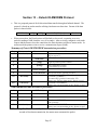
Testing Power and Charging Circuits for MPP III Printer
Test all printers, before returning to Extech, using the following procedure. This will ensure the
fault is with the printer and not some other part of your system.
§
Install a fully charged battery (measuring 5.45 VDC)
§
To ensure a fully charged battery, we recommend you purchase a battery
charger from us (Part # 767500, cost $150.00). The battery charger trickle
charges 4 batteries at a time.
§
Press <OFF> switch and wait until all lights are off
§ Press and hold the <FEED> switch and then insert AC adapter plug into
printer. The printer will print a self test receipt (similar to AC test strip below)
Ÿ
To test the AC adapter use a multimeter and measure output (output
must be > 12.5V)!
Ÿ
If the amber charge light goes on the battery is not fully charged, but
charge circuit is OK
If the receipt is printed, AC power is OK
§
Release <FEED> and remove the AC adapter plug from the printer.
§
Press <FEED> switch and while continuing to press <FEED>, press <ON>.
The printer will print a self test receipt (similar to DC test strip below).
Release <FEED> and <ON> when receipt starts to print
If a self test receipt is generated, DC power is OK
§
Press <OFF> and wait until all lights are off
§
Plug AC adapter into printer. Press <ON>; the green ON-LINE light
illuminates and after 20 seconds the red STATUS light should flash, the
green AC-ON light is illuminated and the ON-LINE light goes off. After 20
seconds all lights go off
Ÿ
If the CHARGE light is on, this will continue on through this test
Remove battery and replace it with a low power battery (around 5.1
VDC)
§
§
Insert AC adapter plug into printer
Page 49
If the amber CHARGE light comes on indicating charge
circuit is OK.
Page 50
Section 15 ... Regulatory Notes
FCC Part 15 Class B
This equipment has been tested and found to comply with the limits for a Class B digital device,
pursuant to Part 15 of the FCC rules. These limits are designed to provide reasonable
protection against harmful interference in a residential installation. This equipment generates,
uses and can radiate radio frequency energy and, if not installed and used in accordance with
the instructions, may cause harmful interference to radio communications. However, there is no
guarantee that interference will not occur in a particular installation. If this equipment does
cause harmful interference to radio or television reception, which can be determined by turning
the equipment off and on, the user is encouraged to try too correct the interference by one or
more of the following measures:
Ÿ
Reorient or relocate the receiving antenna.
Ÿ
Increase the separation between the equipment and the receiver.
Ÿ
Connect the equipment into an outlet on a circuit different from that to which the
receiver is connected.
Ÿ
Consult the dealer or an experienced radio/TV technician for help.
Warranty
This printer is warranted by Extech Data Systems to be free of defects in parts and
workmanship for a period of one year from date of shipment. This warranty does not apply to
defects resulting from action of the user such as misuse, improper wiring, operation outside of
specification, improper maintenance or repair, or unauthorized modification. Extech specifically
disclaims any implied warranties of merchantability or fitness for a specific purpose and will not
be liable for any direct, indirect, special, incidental or consequential damages. Extech's total
liability is limited to the repair or replacement of the product. The warranty set forth above is
inclusive and no other warranty, whether written or oral is expressed or implied.
Warranty Service
A Return Authorization number must be issued before a unit is returned to Extech for repair.
Once a unit has been properly returned to Extech, it will be repaired (estimates are provided
first if the repair cost is estimated above $100.00) and returned via UPS ground. The customer
may elect a faster mode of transport at their cost. The customer is responsible for ensuring
proper packing to prevent damage in transit.
Page 51