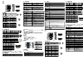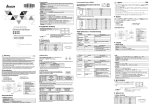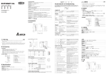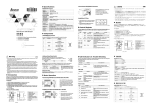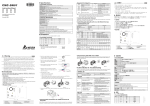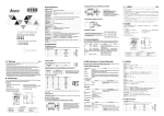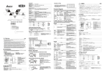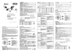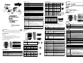
1
 RS-485 Connector
Interface
RJ-11
Transmission method
RS-485
PIN
110/150/300/600/1,200/2,400/4,800/9,600/19,200/38,400/57,600/115,200
Communication format
Stop bit: 1, 2
Communication
protocol
Modbus, User Define
Parity bit: None, Odd, Even
Data bit: 7, 8
ASCII/RTU
Interface
Mini Dim
Transmission method
RS-232
Transmission speed
110/150/300/600/1,200/2,400/4,800/9,600/19,200/38,400/57,600/115,200
Communication format
Stop bit: 1, 2
Communication
protocol
Modbus, Delta Configuration, User Define
Parity bit: None, Odd, Even
Data bit: 7, 8
DVPACAB215/DVPACAB230/DVPACAB2A30
--
Signal
Definition
N/C
4
D-
Negative pole for data
--
N/C
5
GND
Ground
3
D+
Positive pole for data
6
--
N/C
PIN
Signal
Definition
5
--
N/C
6
Rx-
Negative pole for data
receiving
PIN
Signal
1
Tx+
Definition
2
Tx-
3
Rx+
Positive pole for data
receiving
7
--
N/C
4
--
N/C
8
--
N/C
Positive pole for data
transmission
Negative pole for data
transmission
Feed-through terminal 10PIN
Signal
Definition
PIN
Signal
Definition
RS-485
1
--
N/C
5
Tx
Transmission data
Transmission distance
1,200m
2
--
N/C
6
--
N/C
Transmission speed
110/150/300/600/1,200/2,400/4,800/9,600/19,200/38,400/57,600/115,200
3
--
N/C
7
--
N/C
Communication format
Stop bit: 1, 2
4
Rx
Reception data
8
GND
Ground
Parity bit: None, Odd, Even
Data bit: 7, 8
ASCII/RTU
Modbus, User Define
Power voltage
24V DC (-15% ~ 20%) supplied by feed-through terminal
Power consumption
3W
Insulation voltage
500V
Weight
140g
PIN
Signal
Definition
1
SG
Ground of signal
2
D-
Data-
3
D+
Data+
4
X2
Digital input 2
5
X1
Digital input 1
6
X0
Digital input 0
7
S/S
Ground of digital input
8
24V
+24V
9
0V
0V
10
--
Earth ground
Environment
ESD (IEC 61131-2, IEC 61000-4-2): 8KV Air Discharge
EFT (IEC 61131-2, IEC 61000-4-4): Power Line:±2KV, Digital Input: ±2KV,
Communication I/O: ±2KV
RS (IEC 61131-2, IEC 61000-4-3): 80MHz ~ 1GHz, 10V/m. 1.4GHz ~ 2.0GHz,
10V/m
Conducted Susceptibility Test (EN 61000-4-6, IEC 61131-2 9.10): 150kHz ~
80MHz, 3V/m
Surge Test (Biwave IEC 61132-2, IEC 61000-4-5):
Power line 0.5KV DM, Ethernet 0.5KV CM, RS-485 0.5KV CM
Operation: 0ºC ~ 55ºC (temperature), 50 ~ 95% (humidity), pollution degree 2
Storage: -25ºC ~ 70ºC (temperature), 5 ~ 95% (humidity)
International standards: IEC 61131-2, IEC 68-2-6 (TEST Fc)/IEC 61131-2 & IEC
68-2-27(TEST Ea)
Operation/storage
Vibration/shock
immunity
Certificates
4
5
6
7
9
Introduction
digital display shows the address of and errors in IFD9507 and the error messages from the slave.
POWER LED
LED status
Indication
How to correct
OFF
Working power is abnormal
Check if the working power of IFD9507 is normal.
Green light ON
Working power is normal
--
RS-485
Indication
No communication or RS-485
connection is abnormal.
Constantly ON
Abnormal RS-485 connection
Switch D+ and D-
Green light
flashes
RS-485 connection is normal.
--
LED status
RS-232
Indication
1. Auto-detects 10/100 Mbps transmission speed; MDI/MDI-X auto-detection.
2. The monitor table temporarily stores the monitored data for the user to fast save or acquire the data.
5. The station address, RS-485 communication format and baud rate can be set up externally.
6. The communication parameters can be set up through Web.
Address Switch
9
1. Check the power of IFD9507 and make sure the network
connection is normal.
2. Re-power IFD9507. If the error still exists, send your IFD9507
back to the factory for repa$ir.
No power, or no network
connection
Green light ON
The connection is normal, but no
-data transmission.
Green light
flashes
The data transmission is normal. --
Codes in Digital Display
Unit: mm
Code
Indication
01 ~ F7
How to correct
1
Communication ports: RS-485,
Ethernet, RS-232
2
3
4
5
Power indicator
6
RS-485 indicator, Reset button,
Ethernet indicator
7
Module name
8
RS-485 connector, digital input
points, power input point, earth point
0
7-N-1
1
8-N-1
9
8-N-2
F5
Network connection error
Check if IFD9507 is normally connected to the network.
9
DIN rail connector
2
7-O-1
A
7-O-2
F6
Check if the number is too much.
3
8-O-1
B
8-O-2
Full number of devices connected in
the network
F7
UART setting error.
Check if the RS-485, RS-232 communication format is correct.
6
7-E-1
E
7-E-2
E1
Alarm 1 triggered
Check Alarm Input Point 1
7
8-E-1
F
8-E-2
E2
Alarm 2 triggered
Check Alarm Input Point 2
E3
Alarm 3 triggered
Check Alarm Input Point 3
01
Incorrect Modbus function
Check if the Modbus instruction is correct.
02
Incorrect address
Check if the Modbus instruction is correct.
Baud rate (bps)
Switch setting
Baud rate (bps)
03
Incorrect data
Check if the Modbus instruction is correct.
04
CRC error
1. Check if IFD9507 and RS-485 is connected normally.
2. Check if the series transmission speed is consistent with that of
other nodes on the network.
No response from the station
1. Check if IFD9507 and RS-485 is connected normally.
2. Check if the series transmission speed is consistent with that of
other nodes on the network.
Content
Valid Modbus communication address
Data format/baud rate switch
Digit display
Specifications
Ethernet Interface
Data Format Switch
Switch setting
Format
Switch setting
8
Format
The node address of IFD9507 when
in normal operation
--
F0
Returning to default setting
--
F1
IFD9507 is booting.
--
F2
Working power in low voltage
Check if the working power is normal.
F3
Internal memory error
1. Re-power IFD9507. If the error still exists, try step 2.
2. Reset IFD9507. If the error still exists, send it back to the factory
for repair.
F4
Internal error caused by
manufacturing in the factory
1. Re-power IFD9507. If the error still exists, try step 2.
2. Reset IFD9507. If the error still exists, send it back to the factory
for repair.
7-N-2
Baud Rate Switch
Interface
RJ-45 with Auto MDI/MDIX
Transmission method
Ethernet Type II
1
110
7
4,800
Transmission cable
Category 5e, 100m (Max)
2
150
8
9,600
Transmission speed
10/100 Mbps Auto-Detection
3
300
9
19,200
Network protocol
ICMP, IP, TCP, UDP, DHCP, SMTP, Modbus OVER TCP/IP, Ethernet/IP, Delta
Configuration
4
600
A
38,400
5
1,200
B
57,600
6
2,400
C
115,200
Switch setting
接頭
傳輸方式
傳輸速率
通訊格式
通訊協定
傳輸電纜
How to correct
OFF
3. Supports Modbus TCP protocol and Ethernet/IP protocol (supports Master and Slave mode).
4. Able to send out emails after being triggered.
接頭
傳輸方式
傳輸速率
通訊格式
通訊協定
How to correct
1. If the LED is off during the communication, check if the RS-485 in
IFD9507 is normally connected.
2. Check at least 1 node on the network is communicating normally.
LINK/ACT LED
Features
接頭
傳輸方式
傳輸電纜
傳輸速率
網路協定
0B
8
9
功能規格
Ethernet
There are 3 LED indicators and a digital display on IFD9507. POWER indicator displays the status of the
OFF
electric shock and vibration. The enclosure should prevent non-maintenance staff from operating the device (e.g. key
or specific tools are required to open the enclosure) in case danger and damage on the device may occur.
Address switch
產品外觀
1
working power. RS-485 and LINK/ACT indicators display the connection status of the communication. The
LED status
01 … F7
3
LED Indicators & Trouble-Shooting
Dimension
Switch setting
5.
2
RS-485 LED
Installation
Product Profile & Outline
自動偵測 10/100 Mbps 傳輸速率,MDI/MDI-X 自動偵測。
提供 Monitor table 可暫存監控的資料,讓使用者快速存取。
支援 Modbus TCP 協定和 Ethernet/IP 協定(支援 Master 和 Slave 模式)。
經觸發後發送電子郵件。
可由外部設定站號、RS-485 通訊格式、鮑率。
可由 Web 設定通訊參數。
1.
3.
6.
產品簡介
功能特色
Feed-through Terminal PIN Definition
Electrical Specifications
Noise immunity
繁體中文
此安裝手冊只提供電氣規格、一般規格、安裝及配線等。
配線時請務必關閉電源,請勿在上電時觸摸任何端子。
本機為開放型 (OPEN TYPE) 機殼,因此使用者使用本機時,必須將之安裝於具防塵、防潮及免於電擊∕
衝擊意外之外殼配線箱內。另必須具備保護措施(如:特殊之工具或鑰匙才可打開),防止非維護人員操作
或意外衝擊本體,造成危險及損壞。
4.
PIN
Transmission method
Communication
protocol
2.
RS-232 PIN Definition
Interface
ENGLISH
PIN
2
ASCII/RTU
Terminal Block
Warning
Definition
RJ-45 PIN Definition
RS-232 Connector
This instruction sheet only provides introductory information on electrical specification, installation and wiring.
Switch off the power before wiring. DO NOT touch any terminal when the power is switched on.
IFD9507 is an OPEN-TYPE device and therefore should be installed in an enclosure free of airborne dust, humidity,
Signal
1
Transmission speed
Transmission cable
注意事項
RJ-11 PIN Definition
通訊口
電源指示燈
站號設定開關
通訊格式、通訊速率設定開關
數位顯示器
RS-485 指示燈、Reset 按鍵、
Ethernet 指示燈
模組名稱
端子台 RS-485 連接器、數位輸
入點、電源輸入、大地
DIN 軌連接器
RS-485, Ethernet,
RS-232
連接器
RJ-45 with Auto MDI/MDIX
Ethernet Type II
Category 5e, 100
公尺 (Max)
10/100 Mbps Auto-Detection
ICMP, IP, TCP, UDP, DHCP, SMTP, Modbus OVER TCP/IP, Ethernet/IP, Delta
Configuration
連接器
RJ-11
RS-485
110/150/300/600/1,200/2,400/4,800/9,600/19,200/38,400/57,600/115,200
Stop bit: 1, 2
Parity bit: None, Odd, Even
Data bit: 7, 8
ASCII/RTU
Modbus, User Define
連接器
端子台連接器
接頭
傳輸方式
傳輸距離
傳輸速率
通訊格式
通訊協定
電氣規格
電源電壓
消耗電力
絕緣電壓
重量
環境規格
雜訊免疫力
Mini Dim
RS-232
110/150/300/600/1,200/2,400/4,800/9,600/19,200/38,400/57,600/115,200
Stop bit: 1, 2
Parity bit: None, Odd, Even
Data bit: 7, 8
ASCII/RTU
Modbus, Delta Configuration, User Define
DVPACAB215/DVPACAB230/DVPACAB2A30
歐式端子台 10PIN
RS-485
1,200m
110/150/300/600/1,200/2,400/4,800/9,600/19,200/38,400/57,600/115,200
Stop bit: 1, 2
Parity bit: None, Odd, Even
Data bit: 7, 8
ASCII/RTU
Modbus, User Define
24V DC (-15% ~ 20%)
由歐式端子台輸入
3W
500V
140g
ESD (IEC 61131-2, IEC 61000-4-2): 8KV Air Discharge
EFT (IEC 61131-2, IEC 61000-4-4): Power Line:±2KV, Digital Input: ±2KV,
Communication I/O: ±2KV
RS (IEC 61131-2, IEC 61000-4-3): 80MHz ~ 1GHz, 10V/m. 1.4GHz ~ 2.0GHz, 10V/m
Conducted Susceptibility Test (EN 61000-4-6, IEC 61131-2 9.10): 150kHz ~ 80MHz,
3V/m
Surge Test (Biwave IEC 61132-2, IEC 61000-4-5):
Power line 0.5KV DM, Ethernet 0.5KV CM, RS-485 0.5KV CM
0ºC ~ 55ºC(溫度)、50 ~ 95%(濕度)、污染等級 2
操作∕儲存環境 操作:
儲存:-25ºC ~ 70ºC(溫度)、5 ~ 95%(濕度)
國際標準規範
IEC 61131-2, IEC 68-2-6 (TEST Fc)/IEC 61131-2 & IEC 68-2-27 (TEST
耐震動∕衝擊
標準
Ea)
安裝
RS-485
外觀
燈顯示說明
LED 燈狀態
燈滅
無通訊或 RS-485 連線不正常
RS-485 接線不正常
D+、D- 對調
RS-485 連線正常
無需處理
LED 燈狀態
1. 檢查 IFD9507 電源並確認網路線連接正常。
2. 重新上電,如果錯誤依然存在,請退回工廠進行修復。
綠燈亮
連線正常,無資料傳送
無需處理
綠燈閃爍
傳送、接收資料正常
無需處理
數位顯示器顯示說明
有效的 Modbus 通訊位址
通訊格式開關設置
顯示說明
F0
回歸出廠設定值
無需處理
F1
開機中
無需處理
F2
工作電源電壓過低
檢查通訊模組的工作電源是否正常
F3
內部錯誤,內部記憶體檢測出錯
F4
內部錯誤,工廠製造流程出錯
F5
網路連接錯誤
確認通訊模組與網路連接正常
2. 將通訊模組重置,如果錯誤依然存在,退回原廠進行修復。
旋鈕值
通訊格式
F6
網路連線數滿
確認是否連線數過多
7-N-1
8
7-N-2
F7
UART 設定錯誤
確認 RS-485,
E1
警報 1 觸發
查看警報輸入點
1
E2
警報 2 觸發
查看警報輸入點
2
E3
警報 3 觸發
查看警報輸入點
3
9
8-N-2
2
7-O-1
A
7-O-2
3
8-O-1
B
8-O-2
6
7-E-1
E
7-E-2
7
8-E-1
F
8-E-2
通訊速率開關設置
鮑率 (bps)
旋鈕值
鮑率 (bps)
1
110
7
4,800
2
150
8
9,600
3
300
9
19,200
4
600
A
38,400
5
1,200
B
57,600
6
2,400
C
115,200
連接器的腳位定義
1
--
N/C
4
D-
2
--
N/C
資料正極
5
GND
6
--
N/C
腳位
訊號
敘述
5
--
N/C
6
Rx-
接收資料負極
7
--
N/C
8
--
N/C
連接器的腳位定義
訊號
1
Tx+
2
Tx-
3
Rx+
敘述
傳輸資料正極
傳輸資料負極
接收資料正極
4
--
N/C
RS-232
連接器的腳位定義
訊號
訊號
敘述
腳位
訊號
1
--
N/C
5
Tx
敘述
傳輸資料
2
--
N/C
6
--
N/C
3
--
N/C
--
Rx
接收資料
7
4
8
GND
參考地
歐式端子台的腳位定義
訊號
1
SG
2
D-
3
D+
4
X2
5
X1
7
S/S
敘述
資料傳輸參考地
資料負極
資料正極
數位輸入點 2
數位輸入點 1
數位輸入點 0
數位輸入點參考地
8
24V
+24V
9
0V
0V
10
--
6
LED
X0
N/C
環境規格
顯示說明
檢查
工作電源正常
無需處理
站台無回應
噪声免疫力
2. 確認通訊模組串列傳輸速率與網路上其他節點的串列傳輸速率設置
簡體中文
此安装手册只提供电气规格、一般规格、安装及配线等。
配线时请务必关闭电源,请勿在上电时触摸任何端子。
本机为开放型 (OPEN TYPE) 机壳,因此使用者使用本机时,必须将其安装于具防尘、防潮及免于电击/
冲击意外的外壳配线箱内。另必须具备保护措施(如:特殊的工具或钥匙才可打开),防止非维护人员操作
或意外冲击本体,造成危险及损坏。
叙述
引脚
--
N/C
4
D-
110/150/300/600/1,200/2,400/4,800/9,600/19,200/38,400/57,600/115,200
2
--
N/C
5
GND
叙述
数据负极
参考地
6
--
N/C
引脚
信号
Parity bit: None, Odd, Even
Data bit: 7, 8
4.
5.
6.
產品外觀
1
8
9
功能規格
Ethernet
接头
传输方式
传输电缆
传输速率
网络协议
通讯口 RS-485, Ethernet, RS-232
电源指示灯
通讯地址设定开关
通讯格式、通讯速率设定开关
数字显示器
RS-485 指示灯、Reset 按键、
Ethernet 指示灯
模块名称
端子台 RS-485 连接器、数字输入
点、电源输入、大地
DIN 轨连接器
連接器
引脚
Category 5e, 100
米 (Max)
連接器的引腳定義
Mini Dim
1
Tx+
2
Tx-
110/150/300/600/1,200/2,400/4,800/9,600/19,200/38,400/57,600/115,200
3
Rx+
叙述
传输数据正极
传输数据负极
接收数据正极
Stop bit: 1, 2
4
--
N/C
引脚
信号
1
--
2
--
RS-485
3
--
1,200m
4
Rx
Parity bit: None, Odd, Even
Data bit: 7, 8
ASCII/RTU
Modbus, Delta Configuration, User Define
欧式端子台 10PIN
110/150/300/600/1,200/2,400/4,800/9,600/19,200/38,400/57,600/115,200
Parity bit: None, Odd, Even
Data bit: 7, 8
ASCII/RTU
Modbus, User Define
24V DC (-15% ~ 20%)
信号
SG
2
D-
3
D+
4
X2
由欧式端子台输入
3W
500V
140g
操作:0ºC ~ 55ºC(温度)、50 ~ 95%(湿度)、污染等级 2
储存:-25ºC ~ 70ºC(温度)、5 ~ 95%(湿度)
国际标准规范 IEC 61131-2, IEC 68-2-6 (TEST Fc)/IEC 61131-2 & IEC 68-2-27
(TEST Ea)
安裝
有效的 Modbus 通讯地址
通訊格式開關設置
通讯格式
7-N-2
1
8-N-1
9
8-N-2
2
7-O-1
A
7-O-2
3
8-O-1
B
8-O-2
6
7-E-1
E
7-E-2
7
8-E-1
F
8-E-2
通訊速率開關設置
旋钮值
波特率 (bps)
旋钮值
波特率 (bps)
1
110
7
2
150
8
9,600
3
300
9
19,200
4,800
10/100 Mbps Auto-Detection
4
600
A
38,400
ICMP, IP, TCP, UDP, DHCP, SMTP, Modbus OVER TCP/IP, Ethernet/IP, Delta
Configuration
5
1,200
B
57,600
6
2,400
C
115,200
8
GND
大地
N/C
N/C
参考地
0V
燈指示說明及故障排除
通讯模块有三个 LED 指示灯和一个数字显示器。POWER LED 用来显示 IFD9507 的工作电源是否正常;
RS485 LED 与 LINK/ACT LED 用来显示 IFD9507 的通讯连接状态;数字显示器用来显示 IFD9507 通讯模块的
通讯地址、错误信息以及从站的错误信息。
IFD9507
POWER
燈顯示說明
LED 灯状态
显示说明
灯灭
工作电源不正常
绿灯亮
工作电源正常
灯状态
灯状态
燈顯示說明
显示说明
无通讯或 RS-485 联机不正常
RS-485 接线不正常
RS-485 联机正常
燈顯示說明
显示说明
无电源或者网络无连接
联机正常,无数据传送
传送、接收数据正常
數字顯示器顯示說明
代码
04
显示说明
扫描模块的节点地址(正常工作时)
回归出厂设定值
开机中
工作电源电压过低
内部错误,内部存储器检测出错
内部错误,工厂制造流程出错
网络连接错误
网络联机数满
UART 设定错误
警报 1 触发
警报 2 触发
警报 3 触发
错误的功能码
错误的地址
错误的数据
CRC 错误
0B
站台无响应
F6
8
--
+24V
F5
旋钮值
7
--
F4
7-N-1
N/C
N/C
0V
F3
通讯格式
叙述
传输数据
--
9
F0
0
Tx
6
10
01 ~ F7
旋钮值
信号
5
N/C
X0
F2
01… F7
引脚
N/C
24V
F1
说明
叙述
X1
LED
开关设置
N/C
8
灯灭
绿灯恒亮
绿灯闪烁
通訊地址開關設置
N/C
--
S/S
灯灭
绿灯亮
绿灯闪烁
--
8
7
LED
尺寸单位:mm
7
6
RS-485
外觀
接收数据负极
叙述
数据传输参考地
数据负极
数据正极
数字输入点 2
数字输入点 1
数字输入点 0
数字输入点参考地
5
ESD (IEC 61131-2, IEC 61000-4-2): 8KV Air Discharge
EFT (IEC 61131-2, IEC 61000-4-4): Power Line:±2KV, Digital Input: ±2KV,
Communication I/O: ±2KV
RS (IEC 61131-2, IEC 61000-4-3): 80MHz ~ 1GHz, 10V/m. 1.4GHz ~ 2.0GHz,
10V/m
Conducted Susceptibility Test (EN 61000-4-6, IEC61131-2 9.10): 150kHz ~ 80MHz,
3V/m
Surge Test (Biwave IEC 61132-2, IEC 61000-4-5):
Power line 0.5KV DM, Ethernet 0.5KV CM, RS-485 0.5KV CM
Rx-
歐式端子台的引腳定義
1
叙述
--
6
接收数据
引脚
信号
5
連接器的引腳定義
RS-232
DVPACAB215/DVPACAB230/DVPACAB2A30
Stop bit: 1, 2
信号
LINK/ACT
RJ-45 with Auto MDI/MDIX
Ethernet Type II
数据正极
D+
RJ-45
RS-232
自动侦测 10/100 Mbps 传输速率,MDI/MDI-X 自动侦测。
提供 Monitor table 可寄存监控的数据,让使用者快速存取。
支持 Modbus TCP 协议和 Ethernet/IP 协议(支持 Master 和 Slave 模式)。
经触发后发送电子邮件。
可由外部设定通讯地址、RS-485 通讯格式、波特率。
可由 Web 设定通讯参数。
2.
3
ASCII/RTU
Modbus, User Define
LED
9
IFD9507 工作電源是否正常
信号
1
功能特色
1.
連接器的引腳定義
RS-485
產品簡介
7
處理方法
工作電源不正常
0B
2. 確認通訊模組串列傳輸速率與網路上其他節點的串列傳輸速率設置
6
燈顯示說明
綠燈亮
CRC 錯誤
5
大地
燈滅
04
4
RS485 LED
LED 燈狀態
檢查 Modbus 指令是否正確
3
燈指示說明及故障排除
POWER
錯誤的資料
2
通訊模組有三個 LED 指示燈和一個數位顯示器。POWER LED 用來顯示 IFD9507 的工作電源是否正常;
與 LINK/ACT LED 用來顯示 IFD9507 的通訊連接狀態;數位顯示器用來顯示 IFD9507 通訊模組的
站號、錯誤資訊以及從站的錯誤訊息。
IFD9507
03
注意事項
3.
腳位
腳位
檢查 Modbus 指令是否正確
操作/储存环境
耐震动/冲击
标准
敘述
資料負極
參考地
腳位
檢查 Modbus 指令是否正確
錯誤的位址
一致
腳位
D+
錯誤的功能碼
02
一致
敘述
3
电源电压
消耗电力
绝缘电压
重量
1. 檢查通訊模組與 RS-485 連接是否正常
訊號
RJ-45
01
連接器
電氣規格
RS-232 通訊格式是否正確
引脚
Stop bit: 1, 2
1. 檢查通訊模組與 RS-485 連接是否正常
旋鈕值
腳位
RJ-11
RJ-11
接头
传输方式
传输距离
传输速率
通讯格式
通讯协议
1. 將掃描模組重新上電,如果錯誤依然存在,進行步驟 2。
2. 將通訊模組重置,如果錯誤依然存在,退回原廠進行修復。
連接器
端子台連接器
1. 將通訊模組重新上電,如果錯誤依然存在,進行步驟 2。
通訊格式
8-N-1
接头
传输方式
传输速率
通讯格式
通讯协议
传输电缆
0
1
RS-232
處理方法
掃描模組的節點位址(正常工作時) 無需處理
旋鈕值
RJ-11
代碼
01 ~ F7
說明
01… F7
處理方法
無電源或者網路無連接
尺寸單位:mm
開關設置
顯示說明
燈滅
位址開關設置
1. 如通訊中燈滅,檢查 IFD9507 的 RS-485 確認連接正常。
2. 確認網路上至少有一個節點可以正常通訊。
綠燈閃爍
燈顯示說明
接头
传输方式
传输速率
通讯格式
通讯协议
處理方法
綠燈恆亮
LINK/ACT
RS-485
顯示說明
F7
E1
E2
E3
01
02
03
处理方法
检查 IFD9507 工作电源是否正常
无需处理
处理方法
如通讯中灯灭,检查 IFD9507 的 RS-485 确认连接正常。
确认网络上至少有一个节点可以正常通讯。
D+、D-对调。
无需处理
1.
2.
处理方法
检查 IFD9507 电源并确认网络线连接正常。
重新上电,如果错误依然存在,请退回工厂进行修复。
无需处理
无需处理
1.
2.
处理方法
无需处理
无需处理
无需处理
检查通讯模块的工作电源是否正常
1. 将通讯模块重新上电,如果错误依然存在,进行步骤 2。
2. 将通讯模块重置,如果错误依然存在,退回原厂进行修复。
1. 将扫描模块重新上电,如果错误依然存在,进行步骤 2。
2. 将通讯模块重置,如果错误依然存在,退回原厂进行修复。
确认通讯模块与网络连接正常
确认是否联机数过多
确认 RS-485, RS-232 通讯格式是否正确
查看警报输入点 1
查看警报输入点 2
查看警报输入点 3
检查 Modbus 指令是否正确
检查 Modbus 指令是否正确
检查 Modbus 指令是否正确
1. 检查通讯模块与 RS-485 连接是否正常
2. 确认通讯模块波特率与网络上其它节点的波特率设置一致
1. 检查通讯模块与 RS-485 连接是否正常
2. 确认通讯模块波特率与网络上其它节点的波特率设置一致