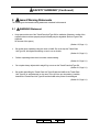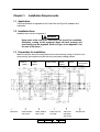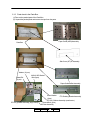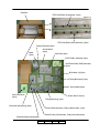
1
Transit Pass Unit Type156 Installation Manual © 2006 Ricoh Printing Systems, Ltd. Sep, 2006 N904131 Revision Table for manual Rev. for Manual 00 01 Machine Rev. - Page No.(Contents) FIRST EDITION 2-4, 2-6, 4-2 (Addition of the BS Plate Assembly) 4-6 (Addition of the Configuration of Post Device) Front cover,Table,Safety2,Safety3,1-1,2-1,2-3,3-1,3-2, 4-1,4-2,4-3,4-4,4-5,4-6 (Change of the product name) Date May.26, ’ 06 Sep.21, ’ 06 © 2006 Ricoh Printing Systems, Ltd. All rights reserved. No part of this document may be reproduced without the expressed permission of Ricoh Printing Systems, Ltd. The material in this document is for informational purposes and is subject to change without notice. Ricoh Printing Systems, Ltd. assumes no responsibility for errors or omissions in this document. No liability is assumed for any damages resulting from the use of the information it contains. This manual describes information for handling and operating the Transit Pass Unit Type156. NOTICE TO USER In an effort to meet the demands of a rapidly changing technology, the manufacturer is continually developing new features and functions to meet your changing printing or Transit Pass Unit Type156 needs. As a result, this manual may not exactly reflect future changes made to the product. Please be sure to consult all manual updates or addenda when using this product’s documentation. INTRODUCTION This manual provides essential information to install the Transit Pass Unit Type156 Carefully read and understand the safety instructions in this manual before starting installation. Keep this manual on hand for reference. BLANK Table of Contents SAFETY SUMMARY 1. General Safety Guidelines …………………………………………………………………. Safety-1 2. Hazard Warning Statements ……………………………………………………………… Safety-2 2.1 WARNING Statement …………………………………………………………………. Safety-2 CHAPTER 1. INSTALLATION REQUIREMENTS ........................................1-1 1.1 1.2 1.3 1.4 1.5 APPLICATION ......................................................................................................................1-1 INSTALLATION AREA ...........................................................................................................1-1 PREPARATION FOR INSTALLATION .......................................................................................1-1 TOOLS REQUIRED ..............................................................................................................1-2 ENVIRONMENTAL CONDITIONS ...........................................................................................1-2 CHAPTER 2. UNPACKING ............................................................................2-1 2.1 UNPACKING OF THE TRANSIT PASS UNIT TYPE156 ............................................................2-1 2.1.1 2.1.2 2.1.3 Confirmation of parts quantities ........................................................................................... 2-1 Unpacking Procedures ........................................................................................................ 2-2 Parts check in the Parts Box................................................................................................ 2-4 CHAPTER 3. PREPARATION FOR INSTALLATION...................................3-1 3.1 PREPARATION FOR INSTALLATION OF THE PASS UNIT..........................................................3-1 3.2 PREPARATION FOR INSTALLATION OF THE STACKER ............................................................3-3 CHAPTER 4. INSTALLATION........................................................................4-1 4.1 4.2 4.3 4.4 4.5 INSTALLATION OF TRANSIT PASS UNIT TYPE156.................................................................4-1 INSTALLATION OF CABLE.....................................................................................................4-3 ADJUSTMENT OF LEVELING HEIGHT.....................................................................................4-5 ATTACHING COVERS...........................................................................................................4-6 CONFIGURATION OF POST DEVICE .....................................................................................4-6 APPENDIX 1. INSTRATION AREA INFORMATION II 01 L 00 Table of Contents i SAFETY SUMMARY The hazard warnings which appear on the warning labels on the machine or in the manual have one of the following alert headings consisting of an alert symbol and a signal word, DANGER, WARINIG, or CAUTION. This is the safety alert symbol. It is used to alert you to potential personal injury hazards. Obey all safety messages that follow this symbol to avoid possible injury or death. 1. DANGER: Indicates an imminently hazardous situation which, if not avoided, will result in death or serious injury. WARNING: Indicated a potentially hazardous situation which, if not avoided, can result in death or serious injury. CAUTION: Indicates a hazardous situation which, if not avoided, will or can result in minor or moderate injury, or serious damage of product. CAUTION: Indicates a potentially hazardous situation which, if not avoided, may result in property damage. General Safety Guidelines Before operating the machine, read the following instructions carefully: Follow all the installation procedures provided in this manual. Pay special attention to and follow all the hazard warnings on the machine and in the manual. Failure to do so can cause injury to yourself or damage to the machine. Do not perform any installation in any way other than as provided in this manual. Keep in mind that the hazard warnings in this manual or on the machine cannot cover every possible case, as it is impossible to predict and evaluate all circumstances beforehand. Be alert and use your common sense. II L 00 Safety 1 SAFETY SUMMARY (Continued) 2. Hazard Warning Statements The following are the hazard warning statements contained in this manual. 2.1 WARNING Statement Keep space at the rear of the Transit Pass Unit Type156 for ventilation. Otherwise, cooling of the equipment does not done properly and print Quality may be degraded. (Refer to Figure in the Appendix. for the area of the space.) (Section 1.2,Page 1-1) Be careful when unpacking using the crane or forklift. Do not to drop the Transit Pass Unit Type156, hit it against something, or turn it over on its side. (Section 2.1,Page 2-1) Perform unpacking where there is no dust or water leaking. (Section 2.1,Page 2-1) Do not place heavy objects which weigh 5 kg or more on the Transit Pass Unit Type156. (Section 2.1,Page 2-1) Be careful when lifting the Transit Pass Unit Type156 with the forklift so the Transit Pass Unit Type156 is well-balanced on the arms of the lift. Also put the packing (cushion) between the Transit Pass Unit Type156 and the forklift so the printer is not damaged. (Section 2.1,Page 2-1) II L 00 01 Safety 2 SAFETY SUMMARY (Continued) Observe the speed limit of 300 mm/sec. (1.08 km/hr) when moving the Transit Pass Unit Type156. Do not move the Transit Pass Unit Type156 on unleveled floor. Do not tilt the Transit Pass Unit Type156 15 deg. or more. (Section 2.1,Page 2-1) Choose the route to move the Transit Pass Unit Type156 where the slope is less than 15 deg. (Section2 .1,age 2-1) Do not push in the direction of the arrow at the movement of the Transit Pass Unit Type156. There is danger to which it falls. (Section 2.1,Page 2-1) Choose the location to place the Transit Pass Unit Type156 where there is no condensation. (Section 2.1,Page 2-1) II L 00 01 Safety 3 Chapter 1. Installation Requirements 1.1 Application These specifications are applicable to the Transit Pass Unit Type156, installation and adjustment. 1.2 Installation Area Installation area is shown in Appendix 1. WARNING Keep space at the rear of the Transit Pass Unit Type156 for ventilation. Otherwise, cooling of the equipment does not done properly and print Quality may be degraded. (Refer to Figure in the Appendix 1 for the area of the space.) 1.3 Preparation for installation Make sure the floor where the leveling bolts to be mounted is strong enough. If the floor is not strong enough, the equipment may tilts and may cause paper handling problem. High Capacity Feeder 2 (Option) Jack Screw High Capacity Feeder 1 (Option) Print Engine With Controller Additional Stacker (Option) Standard Stacker Caster Rotation Caster Rotation Intake Hole For Jack screw Area (Φ82) Area (Φ100) AC Cable and Caster Area (Φ95) II L 01 00 Unpacking 1-1 Transit Pass Unit Type156 (Option) Exhaust Hole 1.4 Tools Required Table 1.1 Tools Required Item Name 1 Cutter 2 Plus Driver 3 Hex Wrench Set 4 5 Spanner (Span: 17mm) Level (Sensitivity; 20’ max.) Usage Unpacking Removing and installing the screw for covers Installing (3mm and 4mm size must be included in the set) Leveling the bolt Check and adjustment of level 1.5 Environmental Conditions Table 1.2 Environmental Conditions Temperature Operation 16 - 32 deg. C (60.8 - 89.6 deg. F) Recommended 19 - 25 deg. C condition (66.2 - 77 deg. F) Non-Operation -10 - 40 deg. C (14 - 104 deg. F) Storage -10 - 40 deg. C (14 - 104 deg. F) Shipment -25 - 50 deg. C (-13 - 122 deg. F) Humidity 20 - 80 %RH Wet Bulb 26 deg.C(78.8 deg. F) max. 40 - 60 %RH 8 - 90 %RH Wet bulb 27 deg. C (80.6 deg. F) max. 5 - 90 %RH 5 - 100 %RH (not to be exposed in the rain/no condensation) 72hr. max. of over 40deg.C environment Altitude : 0 to 2,100 m (0 to 7,000 feet) max. II L 00 Unpacking 1-2 Chapter 2. Unpacking 2.1 Unpacking of the Transit Pass Unit Type156 WARNING 1) Perform unpacking where there is no dust or water leaking. 2) Do not place heavy objects which weights 5 kg or more on the Transit Pass Unit Type156. 3) Observe the speed limit of 300 mm/sec. (1.08 km/hr) when moving the Transit Pass Unit Type156. Do not move the Transit Pass Unit Type156 on unleveled floor. Do not tilt the Transit Pass Unit Type156 15 deg or more. 4) Choose the route to move the Transit Pass Unit Type156 where the slop is less than 15 deg. 5) Do not push in the direction of arrow at the movement of the unit. There danger to which it falls. 6) Choose the location to place the Transit Pass Unit Type156 where there is no condensation. 2.1.1 Confirmation of parts quantities Table 2.1 Components in the package for Transit Pass Unit Type156 Unit of Packing Quantity Main body (Pass Unit) 1 Parts Box 1 II L 01 00 Unpacking 2-1 2.1.2 Unpacking Procedures 1) 2) 3) 4) 5) 6) 7) Cut Bands and remove Cap. Remove the Parts Box.(The Installation Manual is on the Box) Remove Corrugated Paper Sleeve. Remove Upper Pad (4pcs.), Corner Pad (4pcs.)., Remove gummed tape and vinyl. Remove the Slope Board and tapes on the Under Tray. Remove the Installation Manual on the Parts Box and unpack the Parts Box. Cap Corrugated paper sleeve Band Installation Manual Upper pad Corner pad Vinyl Gummed Tape Tape II L 00 Unpacking 2-2 Parts Box 8) Take out the Long Box from the Parts Box and take out the Slope Pad from Long Box. 9) Put the Slope Pad next to the Under Tray. 10) Use the Slope Board and unload the Pass Unit from the Under Tray on the floor. Pass Unit Parts Box Under Pad Long Box Slope Board Slope Pad Under Tray 60 230 Pass Unit Slope Board II L 01 00 Unpacking 2-3 2.1.3 Parts check in the Parts Box. (1) Take out the packed parts of the Parts Box. (2) Unpack the packed parts and remove the tape from the parts. Paper Guide (ADD) Assembly Parts Box Side Cover (ST) W Assembly Washer (12 pcs) Stand Pin (6 pcs) M5x12 HEX Socket Bolt (3pcs) Paper Guide Buffer Assembly PF Out (2) Motor Assembly (large motor) Press Washer FTU Docking Bracket Assembly (3pcs) PF Out (2) Motor Assembly (small motor) Screw M3x6 (1pcs) BS Plate Assembly II L 01 00 Unpacking 2-4 Parts Box RTN Feed Roller (S) Assembly (3pcs) RTN Feed Roller (SGP) Assembly (2pcs) Carbon Electrode (5pcs) Screw M4x16 (2pcs) Band (3pcs) Joint Plate (3pcs) CPHP Cable Assembly (1pcs) Gnd Plate Holder (PHR) Assembly (3pcs) B.B Holder (H) (5pcs) Timing Belt (short) (1pcs) Screw M4x8 (9pcs) One-Touch Bush (2pcs) Screw M4x12 (31pcs) Timing Belt (long) (1pcs) Extension Spring (long) (3pcs) Tension Roller Assembly (Pulley without tooth) (1pcs) Tension Pulley (G) Assembly (Pulley with tooth) (2pcs) Extension Spring (short)(2pcs) II L 00 Unpacking 2-5 Table 2.2 Parts list in the Parts Box No. 1 2 3 4 5 6 7 8 9 10 11 12 13 14 15 16 17 18 19 20 21 22 23 24 25 26 27 28 29 30 Name Q’ ty 3 5 5 2 1 1 2 1 1 1 2 3 1 1 3 1 1 3 3 3 31 9 12 2 2 6 1 3 1 1 RTN Feed Roller (S) Assembly B.B Holder (H) Carbon Electrode RTN Feed Roller (SGP) Assembly PF Out (2) Motor Assembly PF Out (2) Motor Assembly Tension Pulley (G) Assembly Tension Roller Assembly Timing Belt Timing Belt Extension Spring GND Plate Holder (PHR) Assembly Paper Guide Buffer Assembly Paper Guide (ADD) Assembly Extension Spring Side Cover (ST) W Assembly FTU Docking Bracket Assembly Joint Plate M5x12 HEX Socket Bolt Press Washer Screw, M4x12, PAN HD. Phillips Screw, M4x8, PAN HD. Phillips Washer Screw, M4x16, PAN HD. Phillips One-touch Bush Stand Pin CPHP Cable Assembly BAND BS Plate Assembly Screw, M3x6, PAN HD. Phillips II L Note Large Motor Small Motor Short Long Short Long Only use when connecting of the BSR Only use when connecting of the BSR 01 00 Unpacking 2-6 Chapter 3. Preparation for Installation 3.1 Preparation for Installation of the Pass Unit 1) Remove the tapes on the outside of the Pass Unit according to the following photo. Tape Tape 2) Open the Front cover of the Pass Unit. 3) Remove the tape on Paper Guide of the Pass Unit according to the following photo. Tape Front Cover II L 00 01 Preparation for installation 3-1 (4) Unscrew the two screws to remove the Front (U) Cover. (5) Remove the three screws and the three washers from the FTU Docking Bracket Assembly. (6) Fasten the FTU Docking Bracket Assembly on the bottom of the Pass Unit with the three screws, and the three washers which were installed the FTU Docking Bracket Assembly. (7) Unscrew the four screws to remove the Rear Cover. Screw (2 pcs) L Front Cover (FT) Screw (3 pcs ) Washer (3 pcs) FTU Docking Bracket Assembly Screw (4 pcs) Rear Cover II L 00 01 Preparation for installation 3-2 3.2 Preparation for Installation of the Stacker (1) (2) (3) (4) (5) (6) Unscrew the five screws to remove the Rear Cover. Unscrew the four screws to remove the Side Cover (RH). Open the Front Cover (SL) and Front Cover (ADP). Unscrew the four screws to remove the Front Cover (SR) Assembly. Unscrew the two screws to open the PK Box Assembly. Unscrew the four screws to remove the Top Cover. Side Cover (RH) Rear Cover Screw (5pcs) Screw (4pcs) Front Cover (SR) Assembly Screw PK Box Assembly Front Cover (SL) Screw Screw Screw Front Cover (ADP) Top Cover II L 00 Preparation for installation 3-3 (7) Unscrew the four screws to remove the two FD Cover Supports and two FD Cover Bands. (8) Unscrew the nine screws to remove the Top Board (H). FD Cover Band Front Cover (ADP) FD Cover Band Screw (4pcs) FD Cover Support Screw Top Board (H) Screw II L 00 Preparation for installation 3-4 (9) Fasten the six Stand Pins with the six screws (M4x12) and six washers. (10) Fit two One-Touch Bushes onto the holes which are shown in the following figure from the front side. (11) Fasten the two RTN Feed Roller (SGP) Assemblies and B.B Holder (H) with the four screws (M4x12). (12) Fasten the three RTN Feed Roller (S) Assemblies and B.B Holder (H) with six screws (M4x12). (13) Put the five Carbon Electrodes on the three RTN Feed Roller (S) Assemblies and the two RTN Feed Roller (SGP) Assemblies. Screw (M4x12) and Washer (11) Stacker front side view One-Touch Bush From this side Stand Pin Stacker rear side view Screw (M4x12) and Washer One-Touch Bush From this side Stand Pin Return Feed Roller (SGP) Assembly Return Feed Roller (S) Assembly B.B Holder (H) (5 pcs) Screw (M4X12) (10pcs) Carbon Electrode (5 pcs) II L 00 Preparation for installation 3-5 (14) Put the two Timing Belts (short and long) to the three RTN Feed Roller (S) Assemblies and the two RTN Feed Roller (SGP) Assemblies. (15) Fasten the Tension Roller Assemblies and Tension Pulley (G) Assemblies with the three screws(M4x12) loosely. (16) Fasten the two screws (M4x16) from front side of Stacker. (17) Hang the two Extension springs(short) between the two Tension Pulley (G) Assemblies and the two screw(M4x16). (18) Fasten the Tension Roller Assemblies and Tension Pulley (G) Assemblies with the three screws(M4x12) firmly. (19) Fasten the two PF Out (2) Motors with six washers and six screws (M4x12). Extension spring (short) Screw (M4x16) from front side of Stacker Timing Belt (long) Screw (M4x12) Tension Roller Assembly (Roller without teeth) Timing Belt (short) Tension Pulley (G) Assembly PF Out (2) Motor (Small Motor) PF Out (2) Motor (Large Motor) Washer (6pcs) Screw (M4x12)(6pcs) II L 00 Preparation for installation 3-6 (20) Fasten the three GND Plate Holders (PHR) Assemblies with the three screws (M4x8). (21) Fasten the Paper Guide Buffer Assembly with two screws (M4x8). GND Plate Holder (PHR) Assembly Screw (M4x8) Screw for positioning Two places Hole for positioning Two places Paper Guide Buffer Assembly Screw (M4x8) II L 00 Preparation for installation 3-7 (22) Loosen the screw for the Ground cable. (23) Fasten the Paper Guide (ADD) Assembly with four screws (M4x8). (24) Hook the three Extension springs(long) between the Paper Guide (ADD) Assembly and the frame of the Stacker. (25) Fasten the screw for the Ground cable. Screw for the Ground cable Screw for positioning Four places Hole for positioning Four places Paper Guide (ADD) Assembly Screw (M4x8) (4 pcs) Extension Spring (Long) II L 00 Preparation for installation 3-8 (26) Pass the two Sensor Cables from the two One Touch Bushes which were fitted in the Item 3.2 (10) (27) Connect J/P691, J/P692 (the Connector of the Sensor Cable). (28) Connect J/P671(large motor), J/P672(small motor). (the Connector of the Motor Cable). (29) Fasten the PK Box Assembly in the reverse order of Item 3.2 (5). (30) Fasten the three Joint Plates to the Frame with six screws (M4x12). (31) Fasten the Side Cover (ST) to the right side of the Frame with the two screws which were removed in the Item 3.2(2). (32) According to the reverse order of Item 3.2(5), 3.2(6) fasten the two FD Cover Supports and two FD Cover Bands with the four screws (33) Fasten the screw which was loosen in the Item 3.2(19). J/P691 (Connector of Sensor Cable) J/P692 (Connector of Sensor Cable) J/P671 (Connector of large Motor Cable) One Touch Bush One Touch Bush J/P672 (Connector of small Motor Cable) Side Cover (ST) W Assembly Screw (2pcs) (Removed screw in the Item 3.2(2)) Joint Plate (3pcs) Screw (M4x12)(6pcs) II L 00 Preparation for installation 3-9 Chapter 4. Installation 4.1 Installation of Transit Pass Unit Type156 1) Connect the Pass Unit to right side of the Stacker, while fitting the adjustment pin of the Pass Unit into the hole of the stacker. Pass Unit Adjustment pin of the Pass Unit Hole of the stacker Stacker 1~2mm Jack screw Caster II L 01 00 Installation 4-1 2) Fasten the Pass Unit to the Stacker with three M5x12 HEX Socket Bolts and washers. 3) Turn all the Jack screws until they just touch to the floor. 4) Turn all the Jack screws again so that there are about 1mm of space between Casters and floor. (Refer to the drawing of previous page.) M5x12 HEX Socket Bolt and Washer Front side of Pass Unit Rear side of Pass Unit M5x12 HEX Socket Bolt and Washer 5) Fasten the BS plate Assembly with a screw (M3x6). (Only when connecting the Bourg Sheet Rotator to the side of the Pass Unit ) Note. When connecting the BSR to the Pass Unit, insert the BS Plate Assembly between the paper path of the BSR. Screw (M3x6) The paper path of the BSR BS Plate Assembly II L 00 01 Installation 4-2 BS Plate Assembly 4.2 Installation of Cable It is necessary to connect two kinds of cable (AC Cable, CPHP Cable Assembly) 1) Install the CPHP Cable Assembly in the Stacker as shown below. Use the Cable Clamps which were installed, and use the bands which unpacked which were by item 2.1.3. J611 CPHP Cable Assembly Cable Clamp Cable Clamp Cable Clamp AC Cable Tighten the existing Cable and the added Cable together with the Bands Cable Clamp Upper Hole To the Pass Unit II L 01 00 Installation 4-3 2) Connect the CPHP Cable Assembly through the upper hole from the Stacker. 3) Remove the Dummy Connector from the connector of CPHP Cable Assembly. 4) Connect the AC Cable through lower hole from the Pass Unit. 5) Pass the Ground Cable from the lower hole of the Stacker. 6) Remove M5 screw and washer, fasten the Ground Cable with the M5 screw and the washer. 7) Connect the DFA Interface Cable to Post Device, refer to the Installation Manual of Post Device for detail. Washer and M5 Screw CPHP Cable Assembly Ground Cable AC Cable Post Device To Connector of Post Device Pass Unit DFA Interface Cable II L 00 01 Installation 4-4 4.3 Adjustment of leveling height According to the following procedure, adjust the height of Pass Unit. 1) As shown in Fig.1, leveling height is adjusted so that an eye mark can be seen in a slit. 2) Confirm the level of the Pass Unit with the level, turn the Jack screws and adjust the level of the Pass Unit. Slit Eye mark Fig.1 II L 00 01 Installation 4-5 The Level The Level Jack screws 3) Fasten screws completely between the Stacker and the Pass Unit. 4.4 Attaching covers Attach and close all covers which were removed or opened when installation process. 4.5 Configuration of Post Device It is necessary to define post device configuration for Sheet Rotator and Cover Feeder before using Post Device. It can be selected "Installed" or "Not Installed" using following menu of Operator Control Panel. [Setup] - [Service] - [Configuration] - [Post Device Config] - [Sheet Rotator] - [Cover Feeder] II L 01 00 Installation 4-6 Jack screw II L 00 Appendix 1 Unit outline Caster Caster track Door/Drawer Floor cut Area Maintenance area Floor panel Front side And Caster Jack Screw Appendix 1. Installation Area Information Printer installation area information Maintenance Area Unit : mm