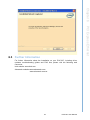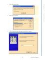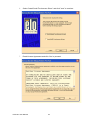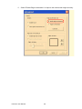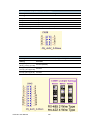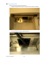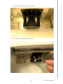
1
User Manual
POC-227
Intel® Core 2™Duo Processor based Point of Care Terminal
with 22" TFT LCD
Instructions for the User
The document combines text and illustrations, providing a comprehensive overview
of the system. The information is presented as a sequential steps of actions, allowing
the user to learn directly how to use the device.
The text provides explanations and instructs the user step-by-step in the practical
use of the product, with short, clear instructions in an easy-to-follow sequence.
Definitions
Warning! A WARNING statement provides important information about a potentially hazardous situation which, if not avoided, could result in death or
serious injury.
Caution! A CAUTION statement provides important information about a potentially hazardous situation which, if not avoided, may result in minor or
moderate injury to the user or patient or in damage to the equipment or
other property.
Note!
A NOTE provides additional information intended to avoid inconveniences during operation.
POC-227 User Manual
Part No. 2008022700
Edition 1
Printed in Taiwan
March 2010
ii
Safety Instructions
Strictly follow these instructions for use; please read these safety instructions carefully.
Keep this user manual for later reference; any use of the product requires full understanding and strict observation of all portions of these instructions. Observe all
WARNINGS and CAUTIONS as rendered throughout this manual and on labels on
the equipment.
Repair of the device may also only be carried out by trained service personnel.
Advantech recommends that a service contract be obtained with Advantech Service
and that all repairs also be carried out by them. Otherwise the correct functioning of
the device may be compromised.
Warning! Because of the danger of electric shock, never remove the cover of a
device while it is in operation or connected to a power outlet.
If one of the following situations arises, have the equipment checked by service personnel:
a. The power cord or plug is damaged.
b. Liquid has penetrated the equipment.
c. The equipment has been exposed to moisture.
d. The equipment does not work well, or you cannot get it to work according to the
user manual.
e. The equipment has been dropped and damaged.
f.
The equipment has obvious signs of breakage.
Disconnect this equipment from any AC outlet before cleaning. Use a damp cloth. Do
not use liquid or spray detergents for cleaning and keep this equipment away from
humidity.
Caution! To avoid short-circuits and otherwise damaging the device, do not allow
fluids to come in contact with the device. If fluids are accidentally spilled
on the equipment, remove the affected unit from service as soon as possible and contact service personnel to verify that patient safety is not
compromised.
Put this equipment on a reliable surface during installation. Dropping it or letting it fall
may cause damage. For plug-in equipment, the power outlet socket must be located
near the equipment and must be easily accessible.
Caution! To prevent overheating, it is recommended to install the unit in an
upright position. Do not lie it flat on a table and do not cover the openings or place the device in direct sunlight or near radiant heaters.
Make sure the voltage of the power source is correct before connecting the equipment to the power outlet. Position the power cord so that people cannot step on it. Do
not place anything over the power cord. If the equipment is not used for a long time,
disconnect it from the power source to avoid damage by transient over voltage.
iii
POC-227 User Manual
Caution! Do not leave this equipment in an uncontrolled environment where the
storage temperature is below -20°C (-4°F) or above 60°C (140°F). This
may damage the equipment.
If your computer clock is unable to keep accurate time or the BIOS configuration
resets to default, please check the battery.
Caution! Do not replace the battery yourself. Please contact a qualified technician
or your retailer.
The computer is provided with a battery-powered real-time clock circuit.
There is a danger of explosion if battery is incorrectly replaced. Replace
only with same or equivalent type recommended by the manufacturer.
Discard used batteries according to the manufacturer’s instructions.
Improper installation of VESA mounting can result in serious personal injury! VESA
mount installation should be completed by a professional technician, please contact
the service technician or your retailer if you need this service. The detailed installation procedure is specified in Appendix A.
CLASSIFICATION:
! Supply Class I adapter
! No applied parts
! IPX1
! Continuous operation
! Not AP or APG category
Warning! This device is not suitable for use in the presence of flammable anesthetic mixtures with air, oxygen, nitrous oxide, or as a life support system.
Maintenance: To properly maintain and clean the surfaces, use only the approved
products or clean with a dry applicator.
Caution! When servicing the device, always use replacement parts that meet
Advantech standards. Advantech Medical cannot warrant or endorse
the safe performance of third-party replacement parts for use with our
medical device.
Make sure users do not come in contact with SIP/SOPs and the patient at the same
time.
POC-227 User Manual
iv
When connecting electrical devices, the operator is responsible for ensuring that the
resulting system meets the requirements set forth by the following standards:
EN 60601-1 (IEC 60601-1)
Medical electrical equipment
Part 1: General requirements for safety
EN 60601-1-1 (IEC 60601-1-1)
Medical electrical equipment
Part 1-1: General requirements for safety
Collateral standard: Safety requirements for Medical electrical systems
EN 60601-1-2 (IEC 60601-1-2)
Medical electrical equipment
Part 1-2: General requirements for safety
Collateral standard: Electromagnetic compatibility; Requirements and tests
Accessory equipment connected to the analog and digital interfaces must be in compliance with the respective nationally harmonized IEC standards (i.e. IEC 60950 for
data processing equipment, IEC 60065 for video equipment, IEC 61010-1 for laboratory equipment, and IEC 60601-1 for medical equipment). Furthermore all configuration should comply with the system standard IEC 60601-1-1. Anyone who connects
additional equipment to the signal input or signal output is configuring a medical system, and is therefore responsible that the system complies with the requirements set
forth in standard IEC 60601-1-1. The unit is for exclusive interconnection with IEC
60601-1 certified equipment in the patient environment and IEC 60XXX certified
equipment outside of the patient environment. If in doubt, consult the technical services department or your local representative.
v
POC-227 User Manual
FCC Class B
This equipment has been tested and found to comply with the limits for a Class B digital device, pursuant to Part 15 of the FCC Rules.
These limits are designed to provide reasonable protection against harmful interference when the equipment is operated in a residential environment. This equipment
generates, uses, and can radiate radio frequency energy. If not installed and used in
accordance with this user's manual, it may cause harmful interference to radio communications.
Note that even when this equipment is installed and used in accordance with this
user's manual, there is still no guarantee that interference will not occur. If this equipment is believed to be causing harmful interference to radio or television reception,
this can be determined by turning the equipment on and off. If interference is occurring, the user is encouraged to try to correct the interference by one or more of the
following measures:
! Reorient or relocate the receiving antenna.
! Increase the separation between the equipment and the receiver.
! Connect the equipment to a power outlet on a circuit different from that to which
the receiver is connected.
! Consult the dealer or an experienced radio/TV technician for help.
Warning! Any changes or modifications made to the equipment which are not
expressly approved by the relevant standards authority could void your
authority to operate the equipment.
List of Accessories
Before installing your Point of Care Terminal, ensure that the following materials
have been received:
! POC-227 series Point of Care Terminal
! Accessories for POC-227
– CD-ROM disc-"Drivers, User's manual and Utilities"
– Mounting kits and packet of screws.
– VESA mounting note x1
– China RoHs note x1
Warning! No user serviceable parts inside, refer servicing to qualified personnel.
Only the accessories indicated on the list of accessories above have
been tested and approved to be used with the device. Accordingly It is
strongly recommended that only these accessories be used in conjunction with the specific device. Otherwise the correct functioning of the
device may be compromised.
POC-227 User Manual
vi
Additional Information and Assistance
Contact your distributor, sales representative, or Advantech's customer service center for technical support if you need additional assistance. Please have the following
information ready before you call:
! Product name and serial number
! Description of your peripheral attachments
! Description of your software (operating system, version, application software,
etc.)
! A complete description of the problem
! The exact wording of any error messages
! This equipment is a source of electromagnetic waves. Before use please make
sure that there are not EMI sensitive devices in its surrounding which may otherwise malfunction.
Environmental Protection
! Follow national requirements to dispose of unit.
Manufacturer
Advantech Co., Ltd.
No.1, Alley 20, Lane 26, Rueiguang Road Neihu District, Taipei,
Taiwan 114, R.O.C.
TEL: (02) 2792-7818
Distributed in Europe by:
Advantech Europe GmbH Kolberger Straße 7
D-40599 Düsseldorf, Germany
Tel: 49-211-97477350
Fax: 49-211-97477300
Visit the Advantech websites at www.advantech.com or www.advantech.com.tw if
you need more information.
vii
POC-227 User Manual
POC-227 User Manual
viii
Contents
Chapter
1
General Information ............................1
1.1
1.2
1.3
Introduction ............................................................................................... 2
Specifications ............................................................................................ 2
Dimensions ............................................................................................... 4
Figure 1.1 Dimensions of the POC-227....................................... 4
VESA Mounting......................................................................................... 5
Figure 1.2 VESA mounting .......................................................... 5
1.4
Chapter
2
System Setup .......................................7
2.1
2.3
2.4
2.5
A Quick Tour of the POC-227 ................................................................... 8
2.1.1 Front View..................................................................................... 8
Figure 2.1 Front view of the point of care terminal ...................... 8
2.1.2 Rear View ..................................................................................... 8
Figure 2.2 Rear view of the point of care terminal ....................... 8
Figure 2.3 Rear view of multi I/O ports ....................................... 9
2.1.3 Bottom View................................................................................ 10
Figure 2.4 Bottom view .............................................................. 10
2.1.4 Right-side Door View .................................................................. 11
Figure 2.5 Right-side door view ................................................. 11
2.1.5 Left-side Door View..................................................................... 11
Figure 2.6 Left-side door view ................................................... 11
Installation Procedures............................................................................ 12
2.2.1 Connecting the Power Cord........................................................ 12
Figure 2.7 Connecting the power cord....................................... 12
2.2.2 Connecting the Ground Pin......................................................... 13
Figure 2.8 POC-227 Equipotential terminal pin ......................... 13
Figure 2.9 Grounding cable with connector ............................... 13
Figure 2.10 POC-227 Equipotential terminal connected with
grounding cable ........................................................ 13
2.2.3 Switch on the Power ................................................................... 14
Figure 2.11 Press the power button to boot system ................... 14
Running the BIOS Setup Program .......................................................... 14
Installing System Software...................................................................... 14
Installing the Drivers................................................................................ 15
3
Chipset ...............................................17
3.1
3.2
3.3
Introduction ............................................................................................. 18
Installation of Chipset Driver ................................................................... 20
3.2.1 Installation for Windows XP ........................................................ 21
Further information.................................................................................. 23
4
Graphics .............................................25
4.1
Introduction ............................................................................................. 26
4.1.1 Intel GM45 Internal Graphics ...................................................... 26
4.1.2 Discrete Graphics Using PCI Express Graphics Attach Port ...... 26
4.1.3 Display Types ............................................................................. 29
Installation of Graphics Driver ................................................................. 30
4.2.1 Intel Internal Graphics Driver Installation .................................... 30
4.2.2 ATI Discrete Graphics Driver Installation .................................... 35
2.2
Chapter
Chapter
4.2
ix
POC-227 User Manual
Chapter
5
Audio Interface.................................. 39
5.1
5.2
5.3
Introduction ............................................................................................. 40
Installation of Audio Driver ...................................................................... 40
5.2.1 Installation for Windows 2000/XP ............................................... 41
Further Information ................................................................................. 42
6
PCI Express Ethernet ....................... 43
6.1
6.2
6.3
Introduction ............................................................................................. 44
Installation of the Ethernet Driver............................................................ 46
6.2.1 Installation for Windows XP ........................................................ 46
Further Information ................................................................................. 49
7
Touch Panel....................................... 51
7.1
7.3
Introduction ............................................................................................. 52
7.1.1 SAW Touch Controller ................................................................ 52
7.1.2 Resistive Touch Controller.......................................................... 52
Installation of Touch Panel Driver ........................................................... 52
7.2.1 Installation for SAW Touch driver ............................................... 52
7.2.2 Installation for Resistive Touch Driver ........................................ 59
Further Information ................................................................................. 64
8
RFID.................................................... 65
8.1
8.2
8.3
Introduction ............................................................................................. 66
Driver Installation .................................................................................... 66
Further Information ................................................................................. 68
9
Smart Card Reader ........................... 69
9.1
9.2
9.3
Introduction ............................................................................................. 70
Installation to the Smart Card Driver....................................................... 70
Further Information ................................................................................. 72
Chapter 10
Intel iAMT, ITPM, ME Interface......... 73
10.1
10.2
Introduction ............................................................................................. 74
Installation of Driver ................................................................................ 75
10.2.1 Install Windows Installer ............................................................. 75
10.2.2 Install .Net framework 3.5 ........................................................... 75
10.2.3 Install iAMT MEI Driver ............................................................... 76
10.2.4 Install iAMT LMS_SOL Driver..................................................... 78
10.2.5 Install iTPM Driver ...................................................................... 81
Chapter 11
Utilities and Hot Fixes ...................... 85
11.1
11.2
Introduction ............................................................................................. 86
Wake up by External USB Device at S3 Resume (Wake up) ................. 86
11.2.1 Installation for Windows XP ........................................................ 86
Chapter 12
Operation and Safety information ... 87
Chapter
Chapter
7.2
Chapter
Chapter
POC-227 User Manual
x
12.1
12.2
12.3
General Safety Guide.............................................................................. 88
Thermal ................................................................................................... 88
Disconnect the Power ............................................................................. 88
Appendix A
MB Connector Map and Table ..........89
A.1
MB Connector Map ................................................................................. 90
Figure A.1 MB Connector Map................................................... 90
Table A.1: MB Connector Table................................................. 91
Appendix B
Front Panel Button ............................93
B.1
Introduction ............................................................................................. 94
Appendix C
POC-227 Advanced BIOS Functions95
C.1
Introduction ............................................................................................. 96
Appendix D
PCM-8703 Jumper Settings ..............99
D.1
Jumper Locations.................................................................................. 100
Figure D.1 PCM-8703 Top Side ............................................... 100
Jumper Settings .................................................................................... 100
Table D.1: Jumper Settings...................................................... 100
Table D.2: CN6 Clear CMOS ................................................... 101
Table D.3: CN7 Clear TPM ...................................................... 101
Table D.4: CN8 VBIOS Select ................................................. 101
Table D.5: CN39 Super I/O GPIO Setup.................................. 102
Table D.6: CN42 COM1 RS-232/422/485 Output Type Settings ...
102
Table D.7: CN63 ME Manufacturing Mode .............................. 103
D.2
Appendix E
Replacing POC-227 System Fuse ..105
E.1
Introduction ........................................................................................... 106
xi
POC-227 User Manual
POC-227 User Manual
xii
Chapter
1
1
General Information
Sections include:
! Introduction
! Specifications
! Dimensions
1.1 Introduction
The POC-227 is a multimedia computer based on the Intel® Core™2 Duo mobile processor that is designed to serve as a Point of Care terminal (POC). It is a PC-based
system with 22" color TFT LCD display, single DVI-I port, dual on-board 10/100/1000
PCI-E Ethernet controller, Quad COM ports, five USB 2.0 ports and a 24-bit stereo
audio controller. The user-friendly POC-227 computer has an optional, replaceable
2.5" SATA disk drive. This highly integrated multimedia system allows system integrators to easily build a Point of Care terminal into their applications. The POC-227 is
an ideal and safe point of care solution for patients and hospital practitioners.
The POC-227 is specially designed to resist spills and water damage, and its protected LCD with sealed ports ensures dust resistance. The high contrast ratio (800:1)
of POC-227 makes it a perfect image terminal for PACS and DICOM applications.
The POC-227 is a reliable solution to various application processing requirements.
1.2 Specifications
Computing
System
Graphics
Expansion Slot
Chipset
GM45/ ICH9M-E Chipset
CPU
Intel® T9400 Core™2 Duo processor, 2.53 GHz,
6M L2 (478-Pin uFCPGA)
Front Side Bus
1066 MHz
Memory
Up to 8 GB DDR3 1066 MHz SDRAM (currently
4 GB due to vendor issue)
Controller
INTEL GM45 with Extreme Graphic technology
Mini PCI
1 x Mini PCI slot, supports type IIIA Mini PCI
PCIe
1 x PCIe x4 slot: support maximal length
241.3mm profile PCIex1 or x4 Card
HDD
1 x 2.5” S-ATA,
Optical
1 x DVD-RW S-ATA
Ethernet
Interface
2 x Gigabit Ethernet (isolated) interface (RJ-45)
Identification
1 x Smart card reader
I/O Ports
3 x RS-232(isolated)
1 x RS232/422/485(isolated) serial port;
5 x USB 2.0 ports;
1 x IEEE 1394a port
1 x PS/2 mouse and K/B;
1 x DVI-I port;
Speakers
2 x 1 W speakers; 1 x MIC-in and headphone Line-out
Storage
Display
POC-227 User Manual
Display type
22” P-MVA TFT LCD.
Max. resolution
1680 x 1050 (WSXGA+)
Max. colors
16.7M colors (RGB 6-bits + HiFRC )
Dot size (mm)
0.282 (per triad) x 0.282
Viewing angle
178°/178°
Luminance
300 cd/m2
Contrast ratio
1000 : 1
LCD MTBF
50,000 hours
Backlight lifetime
50,000 hours at 6.5 mA
2
SAW
Touchscreen
Optional Modules
Certifications
Environment
Physical
Characteristics
Input voltage
100-240 VAC , 2-1 A max. @ 50/60 Hz
Output voltage
+5 V @ 14 A, +12 V @ 10 A, +3.3 V @ 12 A, +5
Vsb @ 1.5 A, -12 V @ 1 A (150 watts)
Type
SAW TS: Surface Wave
Resolution
Corresponding to touch pressure: continuous,
4096 x 4096, plus 255 levels
Light transmission
92%
Controller
RS-232 interface (uses COM6)
Durability
50 million touches
Type
Analog Resistive
Resolution
Continuous
Light transmission
80%
Controller
RS-232 interface (uses COM6)
Durability
36 million touches
MXM-II
MXM Graphics card increases 3D performance
WLAN
Wireless 802.11 b/g/n connection
Bluetooth
Bluetooth v2.0 + EDR
RFID
13.56 MHz RFID with ISO15693 & ISO14443A/B
and active tag function
Light sensor
Ambient light sensor for auto fine tune backlight
DOM
Disk on module (1G ~ 8GB)
CE,FCC Class B Certified
UL60601-1,EN60601-1 Certified
Temperature
0 ~ 40° C (32 ~ 104° F) (Operating)
-20 ~ 60 (Storage)
-20 ~ 60 (Transportation)
Humidity
10 ~ 95%@40 (non-condensing)
5 to 95% (non-condensing) (Storage)
5 to 95% (Transportation)
Shock Resistance
30G peak acceleration (11ms duration)
Water/dust Resistance
IPX1 compliant
Pressure Range
700-1060 hPa (Operation)
375 mmHg to 795 mmHg (Storage)
375 mmHg to 795 mmHg (Transportation)
Dimensions
(W x H x D)
530 x 430 x 135 mm
Weight
12 kg
3
POC-227 User Manual
General Information
Optional
Touchscreen
Internal ATX power supply
Chapter 1
Power Supply
AC Model
1.3 Dimensions
Dimensions: 530 x 430 x 135 (Unit: mm)
530
430
135
Figure 1.1 Dimensions of the POC-227
POC-227 User Manual
4
Chapter 1
1.4 VESA Mounting
VESA Mounting: 75 x 75 mm; 100 x 100 mm
General Information
Figure 1.2 VESA mounting
Optional Modules
! Memory: 1 GB, 2 GB, 4 GB DDR3 1066 MHz SDRAM
! HDD: 2.5" SATA HDD
! Touchscreen: SAW or Analog resistive
5
POC-227 User Manual
Cleaning/Disinfecting
During normal use the POC-227 may become soiled and should, therefore, be
cleaned regularly. Agents: Green tinctured soap and Enzymatic detergents
Steps:
1. Wipe the POC-227 with a clean cloth that has been moistened in the cleaning
solution.
2. Prepare agent per manufacturer's instructions or hospital protocol.
3. Wipe thoroughly with a clean cloth
Caution! Do not immerse or rinse the POC-227 and its peripherals. If you accidentally spill liquid on the device, disconnect the unit from the power
source. Contact your Biomed unit regarding the continued safety of the
unit before placing it back in operation.
Do not spray cleaning agent on the chassis.
Do not use disinfectants that contain phenol. Do not autoclave or clean
the POC-227 or its peripherals with strong aromatic, chlorinated, ketone,
ether, or Esther solvents, sharp tools or abrasives. Never immerse electrical connectors in water or other liquids.
Note!
The Point of Care terminal with the optionally installed touchscreen will
share COM6. Once the touchscreen is installed, COM6 cannot be used
for other purposes.
POC-227 User Manual
6
Chapter
2
2
System Setup
Sections include:
! A Quick Tour of the POC-227
! Installation Procedures
! Running the BIOS Setup Program
! Installing System Software
! Installing the Drivers
2.1 A Quick Tour of the POC-227
Before you start to set up the POC-227, take a moment to become familiar with the
locations and purposes of the controls, drives, connections and ports, which are illustrated in the figures below.
When you place the POC-227 upright on the desktop, its front panel appears as
shown in Figure 2.1.
2.1.1 Front View
Power button
Volume control
Read light control
Touchscreen control
w/indicator light
Brightness control
Figure 2.1 Front view of the point of care terminal
2.1.2 Rear View
When you turn the Point of Care terminal around and look at its rear cover, the
sunken I/O section is at the bottom of the panel PC, as shown in Figure 2.2, and
zoomed in Figure 2.3. (The I/O section includes various I/O ports, including serial
ports, DVI port, the Ethernet port, USB ports, and so on.)
(1)
Figure 2.2 Rear view of the point of care terminal
POC-227 User Manual
8
(3)
(5)
(7)
(6)
(8)
Figure 2.3 Rear view of multi I/O ports
2.1.2 Rear View
(1)
Exchangeable air filter
(2)
Ethernet (network) ports labeled TCP/IP (LAN1) and (LAN2)
(3)
USB1-USB4 ports*
(4)
KB/MOUSE (keyboard/mouse) PS/2 port
(5)
IEEE 1394a port
(6)
Microphone-in & Line out jack
(7)
DVI-I port
(8)
COM1 - COM4 serial ports
Note!
Please clean the air filter monthly for system good cooling.
9
POC-227 User Manual
System Setup
(2)
Chapter 2
(4)
2.1.3 Bottom View
(9)
(10)
(11)
(12)
(13)
Figure 2.4 Bottom view
2.1.3 Bottom View
(9)
Equipotential terminal
(10)
AC inlet
(11)
USB5 port
(12)
Read lights
(13)
Speakers
Note!
Equipotential terminals need to be properly grounded to the hospital
ground/earth system before system boot to protect operator and system.
POC-227 User Manual
10
(14)
Figure 2.5 Right-side door view
2.1.4 Right-side Door View
(14)
HDD 2.5"
(15)
DVD-RW or Blue-ray (optional)
2.1.5 Left-side Door View
(16)
Figure 2.6 Left-side door view
2.1.5 Left-side Door View
(16)
Smart Card Reader
11
POC-227 User Manual
System Setup
(15)
Chapter 2
2.1.4 Right-side Door View
2.2 Installation Procedures
2.2.1 Connecting the Power Cord
The POC-227 can only be powered by an AC power cord. Always handle the power
cords by holding the plug ends only.
Follow these procedures in order:
1. Prepare the POC-227.
2. Connect the female end of the power cord to the AC Power inlet of the POC227.
3. Connect the 3-pin male plug of the power cord to an electrical outlet. (See Figure 2.7)
Figure 2.7 Connecting the power cord
POC-227 User Manual
12
1.
Ready the system and find the equipotential terminal on the rear-side of the
POC terminal.
An equipotential terminal is provided to optionally connect to a hospital ground/
earth system
System Setup
Equipotential terminal
Figure 2.8 POC-227 Equipotential terminal pin
2.
Prepare the grounding cable and the other terminal link to hospital ground/earth
system.
Figure 2.9 Grounding cable with connector
3.
Attach the grounding cable plug with the POC-227 equipotential terminal (See
Figure 2.7)
Figure 2.10 POC-227 Equipotential terminal connected with grounding cable
13
Chapter 2
2.2.2 Connecting the Ground Pin
POC-227 User Manual
2.2.3 Switch on the Power
Switch on the reset switch on the front cover. (See Figure 2.11.)
Figure 2.11 Press the power button to boot system
2.3 Running the BIOS Setup Program
Your POC-227 is likely to have been properly set up and configured by your dealer
prior to delivery. You may still find it necessary to use the BIOS (Basic Input-Output
System) setup program to change system configuration information, such as the current date and time or your type of hard drive. The setup program is stored in readonly memory. It can be accessed either when you turn on or reset the panel PC, by
pressing the "Crtl+Alt+Del" keys on your keyboard immediately after powering on the
computer.
The settings you specify with the setup program are recorded in a special area of
memory called CMOS RAM. This memory is backed up by a battery so that it will not
be erased when you turn off or reset the system. Whenever you turn on the power,
the system reads the settings stored in CMOS RAM and compares them to the
equipment check conducted during the power on self-test (POST). If an error occurs,
an error message will be displayed on screen, and you will be prompted to run the
setup program.
2.4 Installing System Software
Recent releases of operating systems from major vendors include setup programs
which load automatically and guide you through hard disk preparation and operating
system installation. The guidelines below will help you determine the steps necessary to install your operating system on the panel PC hard drive.
Note!
Some distributors and system integrators may have already preinstalled system software prior to shipment of your panel PC.
If required, insert your operating system's installation or setup diskette into the external diskette drive until the release button pops out.
The BIOS supports system boot-up directly from the CD-ROM drive. You may also
insert your system installation CD-ROM disk into your external CD-ROM drive.
Power on or reset the system by pressing the "Ctrl+Alt+Del" keys simultaneously.
The Point of Care terminal will automatically load the operating system from the diskette or CD-ROM.
POC-227 User Manual
14
2.5 Installing the Drivers
Note!
The drivers and utilities used for the POC-227 panel PCs are subject to
change without notice. If in doubt, check Advantech's website or contact
our application engineers for the latest information regarding drivers and
utilities.
15
POC-227 User Manual
System Setup
After installing your system software, you will be able to set up the chipset, graphics,
Ethernet, audio and touchscreen functions using your own external CD-ROM drive.
All the drivers except the CD-ROM drive driver are stored on a CD-ROM disc entitled
"Drivers and Utilities".
The standard procedures for installing the drivers are described in Chapters 3~11
respectively.
The various drivers and utilities on the CD-ROM disc have their own text files which
help users install the drivers and understand their functions. These files are a very
useful supplement to the information in this manual.
For your reference, the directory of drivers on the "Drivers and Utilities" CD-ROM is
"D:\driver" folder
Chapter 2
If you are presented with the opening screen of a setup or installation program, follow
the instructions on screen. The setup program will guide you through preparation of
your hard drive, and installation of the operating system.
POC-227 User Manual
16
Chapter
3
3
Chipset
Sections include:
! Introduction
! Installation of Chipset Driver
3.1 Introduction
The POC-227 uses the Mobile Intel 4 Series Express Chipset Family which is
designed for use in Intel's next generation mobile platforms.
The POC-227 uses the Mobile Intel® GM45 Express chipset, providing outstanding
flexibility for developers of embedded applications with excellent graphics, memory
and I/O bandwidth, as well as remote asset management capabilities, storage speed
and reliability. POC-227 meets the requirements of a broad range of embedded
applications such as retail and transaction solutions, gaming platforms, and industrial
automation equipment. The Mobile Intel GM45 Express chipsets provide the same
feature set and functionality in different form factors.
In this document, the Mobile Intel 4 Series Express Chipset Family is referred to as
the GMCH. And Intel 82801IEM ICH9 Mobile Enhanced (ICH9M-E) is referred to as
the ICH
Processor Information:
! Intel Core 2 Duo mobile processors based on the 45-nm process
! Intel Celeron mobile processors based on the 65-nm process
! 667-MHz, 800-MHz and 1066-MHz FSB
! Other key features are:
– Support for Intel Trusted Execution Technology (Intel TXT) commands and
signaling
– Support for Data Bus Inversion (DBI)
– Support for Intel Virtualization Technology (Intel VT) f or Directed I/O (Intel
VT-d) (DMA)
– Support for Message Signaled Interrupt (MSI)
– 36-bit interface to addressing, allowing the CPU to access the entire 64 GB of
the GMCH's memory address space
– 12-deep, in-order queue to pipeline FSB commands
Memory Information:
! Supports DDR3 SDRAMs
! Support for DDR3 at 800 MHz and 1066 MHz (667 MHz when FSB at 667 MHz)
! Two memory channel configurations supported:
– Dual-channel symmetric (with Interleaved access)
– Dual-channel asymmetric (with or without Intel Flex Memory technology)
! 8 GB maximum memory support
! 64-bit wide per channel
! 256 Mbit, 512 Mbit, 1 Gbit, and 2 Gbit memory technologies supported
! Support for x8 and x16 DDR3 devices
! Support for DDR3 On-Die Termination (ODT)
! No support for Fast Chip Select mode
! No support for ECC
! No support for 1N operation
Intel Trusted Execution Technology (Intel TXT):
! Memory protection from bus masters via No-DMA support (in a secure environment)
POC-227 User Manual
18
Integrated Trusted Platform Module (ITPM):
The GMCH supports an ITPM 1.2 unit within the Intel ME subsystem of the platform.
The GMCH executes validated TPM firmware out of a portion of hardware isolated
DDR DRAM.
These chipsets consist of the Intel? GM45 Graphics Memory Controller Hub
(GMCH), and the Intel? I/O Controller Hub 9M (ICH9M), available in three SKUs. The
ICH9M delivers outstanding system performance through high-bandwidth interfaces
including PCI Express*, Serial ATA, and USB 2.0.
The ICH9 provides extensive I/O support. Functions and capabilities include:
! PCI Express* Base Specification, Revision 1.1 support
! PCI Local Bus Specification, Revision 2.3 support for 33 MHz PCI operations
(supports up to four Req/Gnt pairs).
! ACPI Power Management Logic Support, Revision 3.0b
! Enhanced DMA controller, interrupt controller, and timer functions
! Integrated Serial ATA host controllers with independent DMA operation on up to
four ports (Mobile only) and AHCI support.
! USB host interface with support for up to twelve USB ports; six UHCI host controllers; two EHCI high-speed USB 2.0 Host controllers
!
Integrated 10/100/1000 Gigabit Ethernet MAC with System Defense
! System Management Bus (SMBus) Specification, Version 2.0 with additional
support for I2C devices
! Supports Intel High Definition Audio
! Supports Intel Active Management Technology
! Supports Intel Virtualization Technology for Directed I/O
! Supports Intel Trusted Execution Technology
! Low Pin Count (LPC) interface
! Firmware Hub (FWH) interface support
! Serial Peripheral Interface (SPI) support
! Integrated TPM 1.2 (Mobile Only)
19
POC-227 User Manual
Chipset
Intel Active Management Technology (Intel AMT) 4.0:
The GMCH supports Intel AMT with wired LAN support via a controller link interface
to ICH for extended manageability functionality.
Chapter 3
Intel Virtualization Technology (Intel VT) DMA:
! DMA remapping support via a GMCH remapping engine
! Chipset support for hardware address translation GPA (Guest Physical
Address) to HPA (Host Physical Address)
! Accelerated DMA translation performance via GMCH cache support
! Protected Low-memory Region (<4 GB) and High-memory Region (>4 GB) to
securely store VMM data
3.2 Installation of Chipset Driver
Complete the following steps to install the Chipset driver. Follow the procedures in
the flow chart that apply to the operating system that you are using within your POC227.
Important! The following Windows illustrations are examples only. You must follow
the flow chart instructions and pay attention to the instructions which
appear on your screen.
Note!
The CD-ROM drive is designated as “D” throughout this chapter.
Note!
<Enter> means pressing the “Enter” key on the keyboard.
Note!
Before you install the graphics driver of the POC-227, please ensure
you have installed the “Intel Chipset Software Installation Utility”. You
can find this driver on the Utility CD-ROM.
Note!
The resolution of window display will be fixed at 640 x 480 before you
install the graphics driver. Depending on your monitor’s native resolution, the black area might be different.
POC-227 User Manual
20
1.
3.
Read the License Agreement and click “Yes” to proceed.
Chipset
2.
Double Click "setup.exe" in D:\Driver\XP\Chipset folder. The Install dialog will
appear.
Click 'Next' to continue.
Chapter 3
3.2.1 Installation for Windows XP
21
POC-227 User Manual
4.
Read the file information screen and click “Next” to proceed.
5.
When the 'Setup COMPLETE' message appears click 'Finish' to restart your
computer.
POC-227 User Manual
22
For further information about the installation on your POC-227, included driver
updates, troubleshooting guides and FAQ lists, please visit the following web
resources.
Intel website: www.intel.com
Advantech websites: www.advantech.com
www.advantech.com.tw
Chapter 3
3.3 Further information
Chipset
23
POC-227 User Manual
POC-227 User Manual
24
Chapter
4
4
Graphics
Sections include:
! Introduction
! Installation of Graphics Driver
4.1 Introduction
The POC-227 has an onboard display interface. The specifications and features are
described in the following section:
4.1.1 Intel GM45 Internal Graphics
The POC-227 use the Mobile Intel® GM45 Express chipsets providing outstanding
flexibility for developers of embedded applications with excellent graphics, memory
and I/O bandwidth, as well as remote asset management capabilities, storage speed
and reliability. POC-227 meets the requirements of a broad range of embedded
applications such as retail and transaction solutions, gaming platforms and industrial
automation equipment. The Mobile Intel GM45 Express chipsets provide the same
feature set and functionality in different form factors.
Internal Graphics:
! Intel Gen 5.0 integrated graphics engine with 10 fully programmable cores
! 533-MHz core render clock
! Supports DVI (single channel), LVDS (dual channel 24 bpp), CRT (Via DVI-I
Jack)
! Intel Dynamic Video Memory Technology (Intel DVMT 5.0) to dynamically allocate system memory for graphics usage.
! High performance MPEG-2 decoding
! WMV9 (VC-1) and H.264 (AVC) support
! Hardware acceleration for MPEG2 VLD/iDCT
! Microsoft DirectX*10 support
! Blu-ray* support @ 40 Mb/s
! Hardware motion compensation
! Intermediate Z in classic rendering
4.1.2 Discrete Graphics Using PCI Express Graphics Attach Port
One 16-lane (x16) PCI Express port is provided for external PCI Express-based
graphics card (Optional ATI E2400 MXM Graphics Card)
4.1.2.1 Embedded ATI Radeon E2400 MXM-II Module Key Features
! Complete, proven, robust and ready to use ATI board design
! Faster time to market by leveraging ATI's design and qualification efforts
! Lower system development costs
! Small size
! Up to 16 lane PCI Express support
! TMDS display support
! LVDS panel support
! Analog RGB display support
! Optimized ATI layout for high performance/low-power video memory
POC-227 User Manual
26
Chapter 4
4.1.2.2 ATI Radeon E2400 Key Features
! 180 million transistors using 65nm fabrication process
! Unified superscalar shader architecture
! Microsoft DirectX 10.0
! OpenGL 2.0
! 64-bit 2-channel DDR2/GDDR3 memory interface
! Native PCI Express x16 bus interface
! ATI Avivo HD video and display architecture
! ATI PowerPlay 7.0 power management technology
4.1.2.4 Full Support for Microsoft DirectX 10.0
! Shader Model 4.0
! Geometry Shaders
! Stream Output
! Integer and Bitwise Operations
! Alpha to Coverage
! Constant Buffers
! State Objects
! Texture Arrays
4.1.2.5 Dynamic Geometry Acceleration
! Programmable tessellation unit
! Accelerated geometry shader path for geometry amplification
! Memory read/write cache for improved stream output performance
27
POC-227 User Manual
Graphics
4.1.2.3 Unified Superscalar Shader Architecture
! 40 stream processing units
– Dynamic load balancing and resource allocation for vertex, geometry, and
pixel shaders
– Common instruction set and texture unit access supported for all types of
shaders
– Dedicated branch execution units and texture address processors
! 128-bit floating point precision for all operations
! Command processor for reduced CPU overhead
! Shader instruction and constant caches
! Up to 16 texture fetches per clock cycle
! Up to 128 textures per pixel
! Fully associative multi-level texture cache design
! DXTC and 3Dc+ texture compression
! High resolution texture support (up to 8192 x 8192)
! Fully associative texture Z/stencil cache designs
! Early Z test, Re-Z, Z Range optimization, and Fast Z Clear
! Lossless Z & stencil compression
! 8 render targets (MRTs) with anti-aliasing support
! Physics processing support
4.1.2.6 Anti-aliasing Features
! Multi-sample anti-aliasing (up to 4 samples per pixel)
! Custom Filter Anti-Aliasing (CFAA) for improved quality
! Adaptive super-sampling and multi-sampling
! Temporal anti-aliasing
! Gamma correct
! All anti-aliasing features compatible with HDR rendering
4.1.2.7 Texture Filtering Features
! 2x/ 4x/ 8x/ 16x high quality adaptive anisotropic filtering modes (up to 128 taps
per pixel)
! 128-bit floating point HDR texture filtering
! Bicubic filtering
! sRGB filtering (gamma/degamma)
! Percentage Closer Filtering (PCF)
! Depth & stencil texture (DST) format support
! Shared exponent HDR (RGBE 9:9:9:5) texture format support
4.1.2.8 ATI Avivo. HD Video and Display Platform
! Dedicated unified video decoder (UVD) for H.264/AVC and VC-1 video formats
– High definition (HD) playback of both Blu-ray and HD DVD formats
! Hardware MPEG-1, MPEG-2, MPEG-4/DivX video decode acceleration
– Motion compensation and iDCT (inverse discrete cosine transform)
! Avivo Video Post Processor
– Color space conversion
– Chroma subsampling format conversion
– Horizontal and vertical scaling
– Gamma correction
– Advanced vector adaptive per-pixel de-interlacing
– De-blocking and noise reduction filtering
– Detail enhancement
– Inverse telecine (2:2 and 3:2 pull-down correction)
– Bad edit correction
! Two independent display controllers
– Drives two displays simultaneously with independent resolutions, refresh
rates, color controls and video overlays for each display
– Full 30-bit display processing
– Programmable piecewise linear gamma correction, color correction, and
color space conversion
– Spatial/temporal dithering provides 30-bit color quality on 24-bit and 18-bit
displays
– High quality pre- and post-scaling engines, with underscan support for all display outputs
– Content-adaptive de-flicker filtering for interlaced displays
– Fast, glitch-free mode switching
– Hardware cursor
– Integrated DVI display output
– Supports 18-, 24-, and 30-bit digital displays at all resolutions up to
1920x1200 (single-link DVI)
POC-227 User Manual
28
!
!
!
Integrated 400 MHz 30-bit RAMDAC
– Supports analog displays connected by VGA at all resolutions up to
2048x1536
MPEG-2, MPEG-4, DivX, WMV9, VC-1, and H.264/AVC encoding and
transcoding
Seamless integration of pixel shaders with video in real time
VGA mode support on all display outputs
4.1.3 Display Types
POC-227 supports a single DVI-I jack for a single monitor.
The DVI-I jack supports both DVI Digital I/F and CRT RGB signal.
The analog CRT DAC interface supports a max DAC frequency up to 300 MHz, 24bit RAMDAC, DDC2B compliant, and resolution up to QXGA 2048 x 1536.
The DVI interface supports a single channel DVI interface, and resolution up to
WUXGA 1920x1200.
POC-227 supports a dual channel LVDS interface to an internal 22" wide TFT Panel.
29
POC-227 User Manual
Graphics
4.1.2.9 Display Options
The ATI Radeon E2400 MXM-II module supports the following display interfaces:
! One dual-link LVDS output (24bpp)
! One single-link DVI output
! One independent analog RGB outputs
The ATI Radeon E2400 GPU on the module supports two independent display controllers allowing two separate displays to be driven through a combination of any two
of the display interfaces. All interfaces are routed through the card edge connector to
the mainboard.
Chapter 4
!
4.2 Installation of Graphics Driver
There are two kinds of graphics driver: Intel internal graphics, and ATI discrete
graphics. Install the proper driver based on your hardware configuration.
Caution! Please don't install both the Intel internal graphic driver and the ATI discrete graphics driver on the same system. Only install one graphics
driver.
4.2.1 Intel Internal Graphics Driver Installation
1.
2.
Double Click "winxp_1441.exe" at D:\Driver\XP\Intel Graphics folder. The Install
dialog will appear.
A warring message appears, click "Yes" to continue.
3.
click 'Next' to continue.
POC-227 User Manual
30
Read the License Agreement and click “Yes” to proceed.
5.
Read the file information screen and click “Next” to proceed.
Chapter 4
4.
Graphics
31
POC-227 User Manual
6.
When the 'Click Next to continue' message appears click 'Next' to proceed.
7.
When the 'Setup Is Complete' message appears click 'Finish' to restart your
computer.
POC-227 User Manual
32
Chapter 4
This Intel graphics driver requires the "Microsoft .Net Framework 3.5" in order to work
properly. Please install "Microsoft .Net Framework 3.5" after reboot.
1. Double Click "dotnetfix35.exe" from the D:\Driver\XP\Dotnet35 folder. The
install dialog will appear.
2. Read the license agreement and select "I have read and ACCEPT the terms of
the License Agreement"; click 'Install' to proceed.
Graphics
33
POC-227 User Manual
3.
Download and install progress messages appear, please wait several minutes
for the installation to complete.
Note!
4.
There is no need to connect to the Internet; this install program contains
all files necessary.
When the 'Setup complete' message appears, click 'Exit' to exit the install process. Please restart the system.
POC-227 User Manual
34
Caution! Please don't install both the Intel internal graphics driver and the ATI discrete graphics driver on the same system. Only install one graphics
driver.
1.
35
POC-227 User Manual
Graphics
2.
Double Click "setup.exe" located in the D:\Driver\XP\ATI Graphics folder. The
Install dialog will appear.
Click 'Next' to continue.
Chapter 4
4.2.2 ATI Discrete Graphics Driver Installation
3.
Read the license agreement and click 'Yes' to proceed.
4.
Press the "Express: Recommended" icon to proceed.
POC-227 User Manual
36
6.
Several install progress messages will appear; please wait several minutes for
the installation to complete.
When the 'Setup Complete' message appears click 'Finish' to restart your computer
Chapter 4
5.
Graphics
37
POC-227 User Manual
POC-227 User Manual
38
Chapter
5
5
Audio Interface
Sections include:
! Introduction
! Installation of Audio Driver
! Further Information
5.1 Introduction
The POC-227's onboard audio interface provides high-quality stereo sound by using
the ALC888 audio controller from Realtek. The ALC888 series are high performance
7.1+2 channel High Definition Audio Codecs providing ten DAC channels that simultaneously support 7.1 sound playback, plus 2 channels of independent stereo sound
output (multiple streaming) through the front panel stereo outputs.
Key Features:
! All DACs support 44.1K/48K/96K/192KHz sample rates
! All ADCs support 44.1K/48K/96K sample rates
! Software selectable boost gain for analog microphone input
! All analog jacks are stereo
! Built-in headphone amplifiers for headphone jack
! Supports anti-pop mode when analog power AVDD is on and digital power is
off.
POC-227 contains one headphone output jack (Green color) and one microphone
input jack (Pink color).
There are two internal speakers to provide stereo audio.
5.2 Installation of Audio Driver
Before installing the audio driver, please take note of the procedures detailed below.
You must know which operating system you are using on your POC-227, and refer to
the corresponding installation flow chart. Just follow the steps in the flow chart. You
can quickly and successfully complete the installation, even if you are not familiar
with instructions for Windows.
This setup program will install the audio driver and Realtek utility onto your system.
Important! The following Windows illustrations are examples only. You must follow
the flow chart instructions and pay attention to the instructions which
appear on your screen.
Note!
The CD-ROM drive is designated as “D” throughout this chapter.
Note!
<Enter> means pressing the “Enter” key on the keyboard.
POC-227 User Manual
40
1.
2.
Double Click “WDM_R220.exe” in the D:\Driver\XP\Audio folder. The Install dialog will appear.
Click “Next” to continue.
The install program will install the driver and utility. It will spend a period of time
processing.
Chapter 5
5.2.1 Installation for Windows 2000/XP
Audio Interface
41
POC-227 User Manual
3.
When the 'InstallShield Wizard Complete' message appears click 'Finish' to
restart your computer.
5.3 Further Information
For further information about the audio interface installation on your POC-227,
including driver updates, troubleshooting guides and FAQ lists, please visit the following web resources:
Realtek website: www.realtek.com.tw
Advantech websites:www.advantech.com
www.advantech.com.tw
POC-227 User Manual
42
Chapter
6
6
PCI Express Ethernet
Sections include:
! Introduction
! Installation of Ethernet Driver
! Further Information
6.1 Introduction
The POC-227 is equipped with a high performance PCIe Ethernet chipset Intel
82567LM and Intel 82574L which is fully compliant with IEEE 802.3 10/100/1000
Mbps standards. The Ethernet port provides a standard RJ-45 jack.
Product Features (82567LM)
! Reduced power consumption during normal operation and power down modes
IEEE 802.3 Ethernet interface for 1000BASE-T,100BASE-TX, and 10BASE-T
applications (802.3, 802.3u, and 802.3ab) conformance
! Supports up to 9 Kb jumbo frames (full duplex)
! Supports carrier extension (half duplex)
! Auto-negotiation with support for next page
! Smart speed operation, for automatic speed reduction on faulty cable plants
! Automatic MDI crossover capable
! PMA loopback capable (No echo cancel)
! Advanced power management:
– Low power link up
– Auto Connect Battery Saver - link disconnect
! Advanced cable diagnostics:
– TDR
– Channel frequency response
! Extended configuration load sequence
! Automatic resolution of FDX/HDX mismatch in 10/100 forced configurations
! Dual interconnect between MAC and PHY:
– LCI for 10/100 Mb/s operation control traffic
– GLCI for 1000 Mb/s operation
! Supported ICH Integrated MAC Features:
– Manageability: vPro Compatible
– Performance:
- RSS Support
- Checksum offload
Product Features (82574L)
! PCI Express* (PCIe*)
– 64-bit address master support for systems using more than 4 GB of physical
memory
– Programmable host memory receive buffers (256 bytes to 16 KB)
– Intelligent interrupt generation features to enhance driver performance
– Descriptor ring management hardware for transmit and receive software controlled reset (resets everything except the configuration space)
– Message Signaled Interrupts (MSI and MSI-X)
– Configurable receive and transmit data FIFO, programmable in 1 KB increments
! MAC
– Flow Control Support compliant with the 802.3X specification
– VLAN support compliant with the 802.1Q specification
– MAC Address filters: perfect match unicast
– filters; multicast hash filtering, broadcast filter
POC-227 User Manual
44
!
POC-227 contains two standard RJ-45 Jacks.
! LAN1 (near ACIN jack) is controlled by Intel 82567LM.
! LAN2 is controlled by Intel 82574L.
45
POC-227 User Manual
PCI Express Ethernet
!
Chapter 6
!
– and promiscuous mode
– Statistics for management and RMOM
– MAC loopback
PHY
– Compliant with the 1 Gb/s IEEE 802.3 802.3u 802.3ab specifications
– IEEE 802.3ab auto negotiation support
– Full duplex operation at 10/100/1000 Mb/s
– Half duplex at 10/100 Mb/s
– Auto MDI, MDI-X crossover at all speeds
High Performance
– TCP segmentation capability compatible with Large Send offloading features
– Support up to 256 KB TCP segmentation (TSO v2)
– Fragmented UDP checksum offload for packet reassemble
– IPv4 and IPv6 checksum offload support (receive, transmit, and large send)
– Split header support
– Receive Side Scaling (RSS) with two hardware receive queues
– 9 KB jumbo frame support
– 40 KB packet buffer size
Low Power
– Magic Packet* wake-up enable with unique MAC address
– ACPI register set and power down functionality supporting D0 and D3 states
– Full wake up support (APM and ACPI 2.0)
– Smart power down at S0 no link and Sx no link
– LAN disable function
6.2 Installation of the Ethernet Driver
6.2.1 Installation for Windows XP
1.
2.
Double Click "PRO2KXP_v13_5.exe" found in the D:\Driver\XP\LAN folder. The
Install dialog will appear.
Click “Run” to continue.
3.
Click “Next” to continue.
POC-227 User Manual
46
5.
When the 'Setup Options' message appears click 'Next' to proceed.
PCI Express Ethernet
Read the license agreement and select "I accept the terms in the license Agreement" and click 'Next' to proceed.
Chapter 6
4.
47
POC-227 User Manual
6.
When the 'Ready to Install the program' message appears click 'Install' to proceed.
7.
Several install progress messages will appear; please wait several minutes for
the installation to complete.
When the 'InstallShield Wizard Complete' message appears click 'Finish' to finish the install program.
8.
POC-227 User Manual
48
Chapter 6
PCI Express Ethernet
6.3 Further Information
For further information about the installation on your POC-227, including driver
updates, troubleshooting guides and FAQ lists, please visit the following web
resources:
Intel website: www.intel.com
Advantech websites:www.advantech.com
www.advantech.com.tw
49
POC-227 User Manual
POC-227 User Manual
50
Chapter
7
7
Touch Panel
Sections include:
! Introduction
! Installation of Touch Panel
Driver
! Further Information
7.1 Introduction
The POC-227 is supported by a system integrated touch panel. The touch panel controller is control by the system COM6 interface.
There are two kinds of touch, one is SAW touch, and another one is Resistive touch.
Please install the proper driver based on your hardware configuration.
Caution! Please don't install both the SAW Touch driver and the Resistive Touch
driver on same system. Only install one touch driver based on your
hardware configuration.
7.1.1 SAW Touch Controller
Elo Touch 2701 control board (Elo Part Number D68054-000)
7.1.2 Resistive Touch Controller
SALT AMT PenMount 6200A control board (SALT AMT Part number: PM6200A5)
The POC-227 is supported with a system integrated touch panel. The touch panel
controller is controlled by the system COM6 interface.
7.2 Installation of Touch Panel Driver
7.2.1 Installation for SAW Touch driver
Caution! Please don't install both the SAW Touch driver and the Resistive Touch
driver at same system. Only install one touch driver based on your hardware configuration.
1.
2.
Double Click "SW600821_XPU484.exe" found in the D:\Driver\XP\Touch SAW
folder. The Install dialog will appear.
Click "Run" to continue.
POC-227 User Manual
52
Click 'OK' to extract files
4.
Click 'Unzip' to continue.
5.
"Elo Touchscreen Setup" will appear; click 'Next' to continue.
Chapter 7
3.
Touch Panel
53
POC-227 User Manual
6.
Select "Install Serial Touchscreen Driver" and click "next" to continue.
7.
Read License Agreement and click 'Yes' to proceed.
POC-227 User Manual
54
9.
Select "COM6" and click 'Next' to continue.
Touch Panel
Please don't select "Auto-detect Elo Touch screens"; click "Next" to process.
Chapter 7
8.
55
POC-227 User Manual
10. Confirm the installation lists COM6, click 'Next' to continue.
11. Several install progress messages will appear, please wait several minutes for
the installation to complete.
12. When the SAW Touch driver install completes, you can calibrate the touch
panel, or click 'Finish' to complete.
POC-227 User Manual
56
Chapter 7
13. If you select "Calibrate the Elo Touch monitors":
Please touch the "bullseye" icon in each corner and release. A total of three icon
should be touched to complete the process.
Touch Panel
14. After calibrating the touch panel, click "Elo TouchScreen Properties" found in
the Windows screen, lower-right corner. Select "Properties 1" - "Advanced"
57
POC-227 User Manual
15. Select "Enable Edge Acceleration" to improve the touchscreen edge accuracy.
POC-227 User Manual
58
Caution! Please don't install both the SAW Touch driver and the Resistive Touch
driver on the same system. Only install one touch driver based on your
hardware configuration.
1.
59
POC-227 User Manual
Touch Panel
2.
Double Click "Setup.exe" found in the D:\Driver\XP\Touch RES folder. The
Install dialog will appear.
Click "Next" to continue.
Chapter 7
7.2.2 Installation for Resistive Touch Driver
3.
Read License Agreement and click 'I Agree' to proceed.
4.
When the 'Choose install location' message appears click 'Install' to process.
POC-227 User Manual
60
7.
When the 'Hardware Installation - PenMount 6000 serial' message appears click
'Continue Anyway' to process.
Touch Panel
Several install progress message appear, please wait several minutes to install.
When the 'Hardware Installation - Port (COM, LPT)' message appears click
'Continue Anyway' to process.
Chapter 7
5.
6.
61
POC-227 User Manual
8.
When the 'Hardware Installation - PenMount HID Absolute Pointer' message
appears click 'Continue Anyway' to process.
9.
When the Complete message appears click 'Finish' to finish the install program.
POC-227 User Manual
62
Chapter 7
Calibrate the Panel:
1. Select Windows, Start - Program - PenMount Test Driver - Utility - PenMount
Control Panel:
When PenMount Control Panel appears, please select "PenMount 6000
RS232" and click "Configure" icon
Touch Panel
2.
Select "Standard Calibration" icon
63
POC-227 User Manual
3.
Touch the "Red square" icon until the next "Red square" icon appears. There
are a total of five "Red square" icons that should be touched to complete the
configuration.
7.3 Further Information
For further information about the installation on your POC-227, including driver
updates, troubleshooting guides and FAQ lists, please visit the following web
resources:
Elo Touch website: www.elotouch.com
Advantech websites:www.advantech.com
www.advantech.com.tw
POC-227 User Manual
64
Chapter
8
RFID
Sections include:
! Introduction
! Driver installation
! Further information
8
8.1 Introduction
POC-227 contains an ASTAG PMHNFC0003 RFID module.
RFID readers help nurses identify patients, and verify themselves as authorized caregivers, as well as reducing prescription errors
Features:
! HF READER SUPPORT
! ISO-14443A, ISO-14443B, ISO-15693, Felic, ISO-18000-3 mode 1, Mifare
UltraLight
! Near Field Communication
! NFCIP-1, NFCIP-2, ISO-18092 Compliant, Peer to Peer Communication, Bit
rate from 106k up to 848 kbps
! FREQUENCY: 13.56 Mhz ±7 KHz
Caution! RFID is a optional function; please don't install this driver if you didn't
install the RFID module.
8.2 Driver Installation
1.
2.
Double Click "RFIDUSBDriver.exe" found in the D:\Driver\XP\RFID folder. The
Install dialog will appear.
Click "Next" to continue.
POC-227 User Manual
66
Click "Next" to continue.
4.
When the completion message appears, click 'Finish' to finish the install program.
Chapter 8
3.
RFID
67
POC-227 User Manual
5.
A DOS command window will appear; this window will close automatically.
8.3 Further Information
For further information about the installation on your POC-227, including driver
updates, troubleshooting guides and FAQ lists, please visit the following web
resources.
Advantech websites: www.advantech.com
www.advantech.com.tw
POC-227 User Manual
68
Chapter
9
9
Smart Card Reader
Sections include:
! Introduction
! Installation of Smart Card Driver
9.1 Introduction
POC-227 contains the Castles EZM100PU Card Reader module.
A built-in Smart card reader helps verify clinician identification
Compliant IC Card Standard:
CPU Card: Complies with ISO7816-1, 2, 3
Memory Card: Synchronous 2-line, 3-line and I2C interface
Approval: PC/SC 1.0 Standard
9.2 Installation to the Smart Card Driver
1.
2.
Double Click "Setup.exe" found in the D:\Driver\XP\Card Reader folder. The
Install dialog will appear.
Select language and click "OK" to continue.
3.
Click "Next" to continue.
4.
Click "Install" to continue.
POC-227 User Manual
70
Chapter 9
When the "Smart Card Service Control Tool v1.0" window appears, click "Cancel" to close this window.
71
POC-227 User Manual
Smart Card Reader
5.
6.
When the Completion message appears, click 'Finish' to finish the install program.
9.3 Further Information
For further information about the installation on your POC-227, including driver
updates, troubleshooting guides and FAQ lists, please visit the following web
resources.
Advantech websites: www.advantech.com
www.advantech.com.tw
POC-227 User Manual
72
Chapter
10
10
Intel iAMT, ITPM, ME
Interface
Sections include:
! Introduction
! Installation of Driver
10.1 Introduction
The GMCH supports Intel AMT with wired LAN support via a controller link interface
to ICH for extended manageability functionality.
An Intel AMT engine integrated within the GMCH combines hardware and software
solutions to provide:
! Remote asset management
! Remote diagnostics and repair
! Remote agent presence
! Mobile power management policies
The controller link is the Intel Management Engine (Intel ME) link between the MCH
and the ICH.
iAMT Benefits:
Out-of-Band (OOB) system management allows remote management regardless of
system power or OS state:
! Remote troubleshooting and recovery significantly reduces onsite visits reduces resource and maintenance overhead
! Event logging & alerting decreases downtime & mean time to repair
! Remote HW/SW asset tracking eliminates time-consuming manual inventory
tracking to reduce accounting costs
! Network outbreak containment protects against network outbreaks with realtime filtering
! Agent presence alerts when an agent is unresponsive, enabling the ability to
take action
!
Reduce total cost of ownership for embedded applications
Caution! If iAMT function not use, there is no need to install these drivers.
Caution! Before installing the iAMT driver, enable "AMT BIOS support" in the
BIOS "Advanced Chipset Features". Properly setup the ME settings
from the ME BIOS menu.
Caution! Before installing the iTPM driver, enable "TPM support" in the BIOS
"Security Chip Configuration". Set "TPM status" to "Enable & Activate".
POC-227 User Manual
74
Caution! All four different drivers need to be installed to complete the iAMT function.
10.2.1 Install Windows Installer
Caution! If you have already updated Windows XP to service pack 3, you can
skip this installation.
1.
2.
Double click "WindowsInstaller-KB893803-v2-x86.exe" found in the
D:\Driver\XP\IAMT\ folder. The Install dialog will appear.
Follow the screen instructions to install the service pack.
10.2.2 Install .Net framework 3.5
Caution! If you have already installed the .Net framework 3.5 following the Intel
internal graphics driver installation, you can skip this installation.
For detailed installation procedures, please refer to Chapter 4.2.1.
75
POC-227 User Manual
Chapter 10 Intel iAMT, ITPM, ME Interface
10.2 Installation of Driver
10.2.3 Install iAMT MEI Driver
1.
2.
Double Click "Setup.exe" found in the D:\Driver\XP\IAMT\MEI\ folder. The
Install dialog will appear.
Click 'Next' to continue.
3.
Read license agreement and click 'Yes' to proceed.
POC-227 User Manual
76
Read file information and click 'Next' to proceed.
5.
When the 'Setup Progess' message appears click 'Next'.
77
Chapter 10 Intel iAMT, ITPM, ME Interface
4.
POC-227 User Manual
6.
When the 'Setup is Complete' message appears click 'Finish' to close windows.
10.2.4 Install iAMT LMS_SOL Driver
1.
2.
Double Click "Setup.exe" found in the D:\Driver\XP\IAMT\LMS_SOL\ folder.
The Install dialog will appear.
Click 'Next' to continue.
POC-227 User Manual
78
Read license agreement and click 'Yes' to proceed.
4.
Read file information and click 'Next' to proceed.
79
Chapter 10 Intel iAMT, ITPM, ME Interface
3.
POC-227 User Manual
5.
When the 'Setup Progess' message appears click 'Next'.
6.
When the 'Setup is Complete' message appears click 'Finish' to close windows.
POC-227 User Manual
80
1.
2.
Double Click "Setup.exe" found in the D:\Driver\XP\IAMT\TPM\ folder. The
Install dialog will appear.
Click 'Next' to continue.
3.
Read license agreement and click 'Yes' to proceed.
81
POC-227 User Manual
Chapter 10 Intel iAMT, ITPM, ME Interface
10.2.5 Install iTPM Driver
4.
Read file information and click 'Next' to proceed.
5.
When the 'Setup Progess' message appears click 'Next'.
POC-227 User Manual
82
When the 'Setup is Complete' message appears click 'Finish' to close windows.
83
POC-227 User Manual
Chapter 10 Intel iAMT, ITPM, ME Interface
6.
POC-227 User Manual
84
Chapter
11
11
Utilities and Hot Fixes
Sections include:
! Introduction
! Wake up by External USB
Device at S3 Resume (Wake up)
11.1 Introduction
The POC-227 system needs a specific utility or hot fix to support special functions.
11.2 Wake up by External USB Device at S3 Resume
(Wake up)
POC-227 supports three different sleep (suspend) modes. They are:
1. S1: Power On Suspend: system will stop the clock, turn off the LCD backlight,
but keep all power on. A user can press any key (mouse or keyboard) to wake
up the system.
2. S3: Suspend to RAM: system will stop the clock, turn off most power, not including power to memory. All necessary information will be saved in memory. In this
sleep mode, the system needs a Hot fix to wake up by USB mouse or keyboard.
3. S4: Suspend to Disk (Hibernation): system will stop the clock, turn off most
power, including the memory power. All necessary information will be saved to
hard disk. In this sleep mode, the user needs to press the power button to wake
up the system.
11.2.1 Installation for Windows XP
1.
2.
3.
Double click the "USBRG.REG" found in the D:\Driver\XP\USB folder.
Click “Yes” to install this registry information.
Click “OK” to close the successful installation information window.
POC-227 User Manual
86
Chapter
12
12
Operation and Safety
information
Sections include:
! General Safety Guide
! Thermal
! Disconnect the Power
12.1 General Safety Guide
For your own safety and that of your equipment, always take the following precautions.
Disconnect the power plug (by pulling the plug, not the cord), from your computer if
any of the following conditions exists:
! The power cord or plug becomes frayed or otherwise damaged
! You spill something into the case
! Your computer has been dropped or the case has been otherwise damaged
! You suspect that your computer needs service or repair
! You want to clean the computer or screen
! You want to remove/install any parts
Protecting Your Optical Drive
! To keep your optical drive working properly:
! Position your computer so that the drive tray doesn't bump into anything when it
opens.
! Close the drive when you're not using it.
! Do not put anything on the drive tray when it is open.
! Do not touch the optical drive lens with your fingers. Do not wipe the lens with a
paper towel or other abrasive surface.
12.2 Thermal
The rear metal VESA mounting hole on the POC-227 case functions as a cooling air
flow inlet. The POC-227 case side vent hole serves as a cooling air flow outlet.
These air inlets and outlets transfer heat from inside the computer to the cooler air
outside. Do not block these holes/vents with any soft materials.
Warning! Do not place your POC-227 system on a pillow or other soft material
when it is on, as the material may block the airflow and cause the computer to overheat.
12.3 Disconnect the Power
The only way to disconnect power completely is to unplug the power cord. Make sure
at least one end of the power cord is within easy reach so that you can unplug the
computer when you need to.
Warning! Your AC cord came equipped with a three-wire grounding plug (a plug
that has a third grounding pin). This plug will fit only a grounded AC outlet. If you are unable to insert the plug into an outlet because the outlet is
not grounded, contact a licensed electrician to replace the outlet with a
properly grounded outlet. Do not defeat the purpose of the grounding
plug.
Warning! Never push objects of any kind into this product through the openings in
the case. Doing so may be dangerous and result in fire or a dangerous
electric shock.
Never place anything on system case before turning off computer.
Never turn on your computer unless all of its internal and external parts
are in place.
Operating the computer when it is open or missing parts can be dangerous and can damage your computer.
POC-227 User Manual
88
Appendix
A
A
MB Connector Map
and Table
A.1 MB Connector Map
Figure A.1 MB Connector Map
POC-227 User Manual
90
No.
Description
No.
Description
1
2
ATX Power 20 Pin Connector
31
Bluetooth Module Connector
SATA Connector (For HDD)
32
RFID Module Connector
3
SATA Connector (For ODD)
33
Power Button Board Connector
4
SATA Power Connector
34
PCIEx4 Slot
5
ATX Power for CPU Connector
35
Inverter Connector
6
CPU FAN Connector
36
COM5 Header
7
Ambient Light Sensor Module Connector
37
TOP USB Connector
8
Alarm Light Module Connector
38
Power FAN Connector
9
LVDS Connector (MCH)
39
I2C Connector
10
LVDS Connector (MXM)
40
SYS FAN Connector
11
Lateral USB/Card Reader Connector
41
DDR3 SODIMM Socket 2
12
Touch Control board Connector
42
DDR3 SODIMM Socket 1
13
COM1 Type Header
43
CPU Socket
14
COM1 Jack
44
SPI Flash Header
15
COM2 Jack
45
MXM V2.1 Slot
16
COM3 Jack
46
Mini PCI Socket
17
COM4 Jack
47
System Reset Header
18
DVI-I Jack
48
VBIOS Select
19
N/A
49
EC Flash Header
20
Mic In Jack
50
USB DOM Header
21
Line/Headphone Out Jack
51
GPIO Header
22
1394 Jack
52
Clear TPM Header
23
PS/2 Keyboard / Mouse Jack
53
Clear CMOS Header
24
USB Jack
54
USB Header
25
USB Jack
55
ME Manufacture Mode Header
26
USB Jack
56
RTC Battery Socket
27
USB Jack
57
MXM FAN Connector
28
RJ45 Jack (LAN 2)
58
Left Speaker Connector
29
RJ45 Jack (LAN 1)
59
Right Speaker Connector
30
Front Button Connector
91
POC-227 User Manual
Appendix A MB Connector Map and Table
Table A.1: MB Connector Table
POC-227 User Manual
92
Appendix
B
B
Front Panel Button
B.1 Introduction
POC-227 front button function description:
Front button map
Button Description:
Power button
Press this button to power on/off system. When system on, this icon
will turn green.
Reduce volume
Press this button to reduce speaker and headphone volume
Increase Volume
Press this button to increase speaker and headphone volume
Touch disable
Press this button to disable/enable touch function. When touch function is disabled, this icon will turn yellow.
Read light
Press this button to enable/disable Read light.
Reduce brightness
Press this button to reduce LCD backlight brightness
Increase brightness
Press this button to increase LCD backlight brightness
Combination Button:
One special function is the backlight off function. When you press both reduce brightness and increase brightness buttons for half a second, the LCD backlight will be
turned off. And press both buttons for half second again; LCD backlight will be turn
on.
When the backlight is off, POC-227 system is still running; there is no impact to running program.
This backlight off function can be used in a hospital environment.
If a doctor needs to check an X-Ray photo in a dark room environment, an operator
can quickly turn off the backlight to prevent interference.
A nurse can turn off the backlight at night to prevent disturbing a sleeping patient.
POC-227 User Manual
94
Appendix
C
C
POC-227 Advanced
BIOS Functions
C.1 Introduction
POC-227 advanced function BIOS menu.
1. Ambient Light Sensor
Enable/disable ambient light sensor (Optional) function in the BIOS menu. The ambient light sensor will detect the ambient luminance to control LCD backlight luminance
automatically.
BIOS Menu location:
BIOS Menu - Integrated Peripherals - Onboard Device - Ambient Light Sensor
Enable: LCD backlight luminance controlled by light sensor automatically.
Disable: LCD backlight luminance controlled by front button. (Default)
2.
Power Button work in S0
Enable/disable power button function in BIOS menu. If you disable the power button
in S0 (System ON) status, the power button will not function. A user must use software to turn off the system. This function can prevent accidental shutdown of the system.
BIOS Menu location:
BIOS Menu - Integrated Peripherals - Onboard Device - Power Button work in S0
Enable: Power button works when system is in S0 (System ON) status. (Default)
Disable: Power button does not work when system in S0 (System ON) status.
3. LCD Backlight Button
Enable/disable LCD Backlight button function in BIOS menu. If you disable the LCD
backlight button, the button will not function. This function can prevent accidental
adjustment of LCD backlight luminance.
BIOS Menu location:
BIOS Menu - Integrated Peripherals - Onboard Device - LCD Backlight Button
Enable: Front LCD Backlight adjust button control function works. (Default)
Disable: Front LCD Backlight adjust button control function does not work.
4. Front volume Button
Enable/disable front volume button function in BIOS menu. If you disable the front
volume button, this button will not function. This function can prevent accidental
adjustment of speaker volume.
BIOS Menu location:
BIOS Menu - Integrated Peripherals - Onboard Device -Front volume Button
Enable: Front volume adjust button control function work. (Default)
Disable: Front volume adjust button control function not work.
5. DVI Drive Strength
Increase the DVI signal drive strength in BIOS menu. If you connect a longer DVI
cable, you can adjust the drive strength to improve the DVI signal transfer capability.
POC-227 User Manual
96
Appendix C POC-227 Advanced BIOS Functions
BIOS Menu location:
BIOS Menu - Advanced Chipset Features - DVI Drive Strength
Normal: Normal driver strength. (Default)
Strong/Stronger/Strongest: Higher drive strength.
97
POC-227 User Manual
POC-227 User Manual
98
Appendix
D
D
PCM-8703 Jumper
Settings
D.1 Jumper Locations
CN6 CN8
CN63
CN7
CN39
* All jumpers are located on the top side of the board
Figure D.1 PCM-8703 Top Side
D.2 Jumper Settings
Table D.1: Jumper Settings
CN6
Clear CMOS
CN7
Clear TPM
CN8
VBIOS Select
CN39
Super I/O GPIO Setup
CN42
COM1 (RS-232/422/485) Select
CN63
ME Manufacturing Mode
POC-227 User Manual
100
CN42
Appendix D PCM-8703 Jumper Settings
Table D.2: CN6 Clear CMOS
Description
Clear CMOS Setup
Setting
Function
(1-2)
Clear CMOS Setup
(No Connection)
Normal Operation (Default)
Table D.3: CN7 Clear TPM
Description
Clear TPM Setup
Setting
Function
(1-2)
Clear TPM Setup
(No Connection)
Normal Operation (Default)
Table D.4: CN8 VBIOS Select
Description
Select Different VBIOS Settings
Setting
Function
(No Connection)
VBIOS 1(Default)
(1-2)
VBIOS 2
(2-3)
VBIOS 3
(1-2),(3-4)
VBIOS 4
101
POC-227 User Manual
Table D.5: CN39 Super I/O GPIO Setup
Description
Select Different GPIO Settings
Setting
Function
(1-2)
Super I/O GPIO 22 Active
(3-4)
Super I/O GPIO 23 Active
(5-6)
Super I/O GPIO 24 Active
(7-8)
Super I/O GPIO 27 Active
(No Connection)
Normal Operation (Default)
Table D.6: CN42 COM1 RS-232/422/485 Output Type Settings
Description
COM1 RS-232/422/485 Output Type Settings
Setting
Function
(5-6), (7-9),
RS-232 (Default)
(8-10), (13-15), (14-16)
(3-4), (9-11)
RS-422
(10-12), (15-17)(16-18)
(1-2), (9-11)
(10-12), (15-17)(16-18)
POC-227 User Manual
RS-485
102
Appendix D PCM-8703 Jumper Settings
Table D.7: CN63 ME Manufacturing Mode
Description
ME Manufacturing Mode
Setting
Function
(1-2)
ME Manufacturing Mode
(No Connection)
Normal Operation (Default)
103
POC-227 User Manual
POC-227 User Manual
104
Appendix
E
E
Replacing POC-227
System Fuse
E.1 Introduction
POC-227 system fuse replacement instructions:
1. Unplug ACIN power cord and wait 1~5 minutes to allow system to discharge.
2.
Pry the fuseholder open with a slotted screwdriver
POC-227 User Manual
106
Pull out the fuseholder to expose the fuse.
4.
Use a pair of tweezers to pull the fuse out.
107
Appendix E Replacing POC-227 System Fuse
3.
POC-227 User Manual
5.
Replace both fuses with a certified part (see part no. below).
Advantech Part number: 1750000297
Vendor: Littelfuse
Vendor Part number: 02153.15MXP
Warning! Do not use another fuse, even if the fuse looks similar with the old part.
Only use an Advantech certified fuse.
6.
Reverse the procedure from steps 4 to 1 to install the fuse and close the fuseholder.
POC-227 User Manual
108
Appendix E Replacing POC-227 System Fuse
POC-227 User Manual
109
www.advantech.com
Please verify specifications before quoting. This guide is intended for reference
purposes only.
All product specifications are subject to change without notice.
No part of this publication may be reproduced in any form or by any means,
electronic, photocopying, recording or otherwise, without prior written permission of the publisher.
All brand and product names are trademarks or registered trademarks of their
respective companies.
© Advantech Co., Ltd. 2010