1
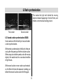
TV • VIDEO • CAMCORDER • MECABLITZ
MECABLITZ 34 AF-3 M
Operating instructions
Foreword
Dear Customer,
Please read these operating instructions carefully,
even if, at first sight, some points may not appear
to
be of interest. Our design work placed particular
value on ensuring that operation of the mecablitz is
as simple as possible, but it should be noted that
the system cameras for which the flashgun is
intended offer a great diversity of capabilities.
We thank you for your confidence in our mecablitz MB 34 AF-3M.
The MB 34 AF-3M flashgun has been especially designed for Minolta system cameras of the
Dynax series. IMPORTANT: Never mount the
flashgun in the accessory shoe of any other
system camera, otherwise the flashgun’s foot
or the camera’s accessory shoe can be destroyed! The dedicated contacts in the foot of the
MB 34 AF-3M only support the controlling
commands of Minolta system cameras.
We wish you much pleasure with your new Metz
flashgun in conjunction with a Minolta Dynax
system camera to light up the darkest points, and
for creative flash lighting.
The following pages give details for the correct
operation of the mecablitz flashgun and summarize its fields of application.
1
Contents
6.
6.1
6.2
6.3
7.
8.
9.
9.1
9.2
10.
11.
Flash synchronisation . . . . . . . . . . . . . . .30
Normal synchronisation . . . . . . . . . . . . . . .30
Slow-synchronisation . . . . . . . . . . . . . . . .30
Second curtain synchronisation . . . . . . . . .31
Flash in the individual camera modes . .32
Autofocus measuring flash . . . . . . . . . . .33
Flash techniques and flash functions . .34
Automatic fill-in flash . . . . . . . . . . . . . . . .34
Exposure correction . . . . . . . . . . . . . . . . .34
Lighting and attachments . . . . . . . . . . . .35
Care and maintenance Manual firing button
Troubleshooting . . . . . . . . . . . . . . . . . . .36
12. Technical data . . . . . . . . . . . . . . . . . . . . .37
Lighting distances . . . . . . . . . . . . . . . . . .38
1.
2.
2.1
2.2
2.3
2.4
3.
3.1
3.2
4.
4.1
4.2
4.3
4.4
Safety instructions . . . . . . . . . . . . . . . . .23
Preparing the mecablitz for use . . . . . . .24
Power supply . . . . . . . . . . . . . . . . . . . . . .24
Loading and replacing the batteries . . . . . .24
Automatic flashgun cut-out circuit . . . . . . .25
Mounting/Removing the mecablitz . . . . . . .25
Setting the mecablitz into operation . . .26
Preconditions . . . . . . . . . . . . . . . . . . . . . .26
Switching the flashgun on and off . . . . . . .26
Flashgun instructions to the camera . . .27
Flash-ready indication . . . . . . . . . . . . . . . .27
Automatic flash sync speed control . . . . . .27
Correct-exposure indication . . . . . . . . . . .27
Information displayed in the
camera’s viewfinder . . . . . . . . . . . . . . . . .28
5. TTL flash control . . . . . . . . . . . . . . . . . . .29
2
1. Safety instructions
• NEVER fire a flash in the immediate vicinity of
the eyes! Flash fired directly in front of the eyes
of a person or animal can damage the retina and
lead to severe visual disorders - even blindness!
• In the event of flash shots with full light output
observe an interval of at least 3 minutes after a
series of 20 flashes. This will protect the flashgun against overload.
• Spent batteries should be immediately removed. Chemicals leaking out of spent batteries
will damage the flashgun.
• NEVER place material that is impervious to light
in front of, or directly on, the reflector screen.
The reflector screen must be perfectly clean
when a flash is fired. The high energy of the
flash light will burn the material or damage the
screen if this is not observed!
• Do not short-circuit batteries! DANGER OF
EXPLOSION!
• Batteries should not be exposed to excessive
heat, for instance sunshine, fire and the like!
• NEVER dismantle the flashgun! DANGER: HIGH
VOLTAGE! There are no components inside the
flashgun that can be repaired by a layperson.
• NEVER throw spent batteries in a fire!
• Do not expose the flashgun to dripping or
splashing water!
Disposal of batteries
Do not dispose of spent batteries with domestic
rubbish.
Please return spent batteries to collecting points
should they exist in your country!
• Protect the flashgun against excessive heat and
high humidity levels! Do not keep the flashgun
in the glove compartment of a car!
3
2. Preparing the mecablitz for use
☛
2.1 Power supply
The flashgun can only be operated with 2 CR2-type lithium batteries. This type of battery can be stored for many
years with practically no loss of energy, thus making it
ideal for occasional amateur flash photography.
☞ Batteries have become discharged or spent
when recycling takes more than 60 seconds.
The batteries should be removed from the
mecablitz if the flashgun is not going to be used
for a prolonged period.
➭
Fig. 1: Unlocking and exchanging batteries
2.2 Loading and exchanging batteries
• Turn off the flashgun with the main switch.
• Press the unlocking catch, slide the battery
compartment lid to the right and fold open (see
fig. 1).
• Insert the batteries according to the indicated
battery symbols.
The supplied lithium batteries are expendables
and, as such, are not subject to our warranty provisions.
After the batteries have been inserted, fold down
the battery compartment lid, and push to the left
until it engages audible with the unlocking catch.
4
2. Preparing the mecablitz for use
☞ When loading the batteries ensure correct pola-
2.4 Mounting/Removing the flashgun
• Turn off the mecablitz.
• Press the unlocking catch at the back of the
mecablitz (see fig. 2).
• Slide the mounting foot into the camera’s
mounting shoe.
• Always turn off the flashgun before it is removed.
• Press the unlocking catch at the back of the
mecablitz (fig. 2) and withdraw from the camera.
rity. Incorrectly loaded batteries can destroy the
flashgun! All batteries must be of the same
make and have the same charge level. Exhausted batteries must not be thrown into the
dustbin! Contribute to the protection of the
environment and discard exhausted batteries
at the appropriate disposal points.
☛
2.3 Automatic flashgun switch-off
To avoid accidental battery discharge the flashgun
automatically switches itself off to save power
approximately 8 minutes after
- the flashgun was switched on
- the last flash was fired
- tripping the camera release, or
- switching on the camera light metering system.
The green flash-ready indicator is turned off.
To turn on the mecablitz again switch the main
switch OFF and then ON. The flashgun should
always be turned off if it is not being used.
Fig. 2: Unlocking catch
5
3. Setting the mecablitz into operation
3.1 Preconditions
The mecablitz must only be used with TTL
flash controlled cameras!
The sensor of TTL flash controlled cameras
measures the light reaching the film through
the camera lens and instantly cuts out the
flash when the film has been correctly exposed. Please refer to the camera’s operating
instructions to find out whether your camera
features this function.
OFF
ON
Ǻ
A full-power flash is fired if the camera does
not feature TTL flash control!
Fig. 3: Switching the flashgun on and off
In other words: Without TTL flash control, the
mecablitz fires an unmeasured flash at maximum
output.
3.2 Switching the flashgun on and off
Set the main switch in the ON position to turn on
the flashgun. The green flash-ready indicator
lights up to indicate flash readiness.
If there is a flashgun integrated in the camera it
must be switched off or completely folded
down when the mecablitz is used.
Set the main switch in the OFF position to turn off
the flashgun.
6
4. Flashgun instructions to the camera
The mecablitz transmits different signals and
messages to the camera when it is connected to
the camera and is switched on.
4.2 Automatic flash sync speed control
Most system cameras automatically change to
flash sync speed when flash readiness is reached.
The flash sync shutter speeds may vary between
1/30th and 1/300th second, depending on the
camera model. Please refer to the camera’s operating instructions for further details.
4.1 Flash-ready indication
The green light on the mecablitz illuminates
when the flash capacitor is fully primed, thereby
indicating flash readiness. This means that flash
can be used for the next exposure. The flash readiness signal is transmitted to the camera where it
is indicated by a corresponding display in the
camera’s viewfinder. On some cameras (depending on the model) the shutter is automatically
changed to flash sync speed when flash readiness
is reached. The flash will not be fired if the shutter
is released before the flash ready light illuminates
with the result that the exposure may be incorrect
if the camera control circuit has already changed
over to flash sync speed. Please refer to the camera’s operating instructions for further details.
4.3 Correct-exposure indication (see fig. 4)
The red correct exposure light briefly illuminates
when flash exposure was correct. At the same
time the mecablitz sends an o.k. signal to the
camera for display in the viewfinder.
Please refer to the camera’s operating instructions
for further details.
7
4. Flashgun instructions to the camera
Fig. 4: Exposure o.k.
Permanently 2)
illuminated
or blinks slowly1)
The flashgun is primed and
ready for firing
Permanently
illuminated 2)
or blinks slowly1)
The flashgun is primed and
ready for firing
blinks 2)
blinks rapidly 1)
The light output was sufficient
for correct exposure
Camera models:
3xi / 2xi / SPxi / 5000i / 3000i
4.4 Information displayed in the camera’s viewfinder
Camera models
8000i 1)/ 7000i 1)/ 700si 2)
9xi 2)/ 7xi 2)/ 5xi 2)
blinks
The flashgun is being primed
blinks slowly
Displays in
viewfinder
blinks rapidly
The flashgun is primed and
ready for firing
The light output was sufficient
for correct exposure
Permanently
illuminated
Meaning
The flashgun will be triggered as
soon as the release is pressed.
8
5. TTL flash control
The mecablitz receives its information exclusively
from the connected TTL-controlled camera.
The table on page 37 gives the maximum range
for the selected aperture. The minimum lighting
distance is approx. 15% of the maximum threshold range.
Exposure measurement in TTL mode (TTL =
through-the-lens) is completed by the camera’s
sensor. This sensor measures the light reaching
the film through the camera lens. An electronic
control circuit within the camera transmits a stop
signal to the flashgun as soon as the film has been
exposed by the correct amount of light; the flash is
then instantly cut out.
If the actual distance is shorter than the
minimum lighting distance, then this may
result in overexposure.
The speed of films to be exposed under
TTL flash control must be between ISO
25/15°* and ISO 1000/31°. Correct exposures cannot be guaranteed with other
film speeds.
A strip of film must be loaded in the camera if tests
are to be conducted in TTL flash mode. The effective flash range can only be checked by the correct-exposure display (o.k.) if the flash is triggered
by the camera and not with the manual release on
the flashgun!
The advantage of the TTL mode is that all factors
influencing the exposure of the film (such as filters, change of aperture or variable aperture
zooms) are taken into account. You need not worry
about adjustment of the light output. The camera’s
electronic system automatically defines the required amount of light. You can also utilize various
metering facilities (e.g. spot , matrix or centreweighted overall readings) offered by some cameras.
*
9
With automatic film speed setting (DX): ISO 32/16°
6. Flash synchronisation
Flash shots at low lighting levels and fast shutter
speeds (normal flash sync speed) can often result
in overexposed subjects in front of a very dark
back-ground.
Different modes of flash synchronisation are possible, depending on the camera model. Please
refer to the camera’s operating instructions to find
out how the individual modes of synchronisation
are set on the camera.
The slow-sync function allows the use of slow
shutter speeds right up to 30 seconds, to significantly enhance the background as a result of the
extra ambient light. Such shots require a tripod to
prevent camera shake. Please refer to the camera’s operating instructions for further details.
6.1 Normal synchronisation
This mode is available with all TTL cameras, and it
is suitable for most flash shots. With normal
synchronisation, switching to the camera’s flash
sync shutter speed is automatic. The shutter
speed may vary from 1/30th and 1/300th seconds,
depending on the camera model. Please refer to
the camera’s operating instructions for further
details.
6.2 Slow-synchronisation
Some cameras feature specific exposure programs for slow-synchronisation.
10
6. Flash synchronisation
This makes the light trail behind the moving
objects instead of appearing in front of them, and
renders a more natural looking picture.
First curtain
Second curtain
6.3 Second curtain synchronisation (REAR)
Some cameras offer the facility of second shutter
curtain synchronisation.
With normal synchronisation, the flash is fired precisely after the opening of the first shutter curtain.
When using slow shutter speeds, and with moving
objects, this would result in an unnatural rendition
of light traces.
With second curtain or rear curtain synchronisation, the flash is fired as the exposure is ending, just
before the second curtain covers the film again.
11
7. Flash in the individual camera modes
Auto program mode with flash (P-function)
In this mode, the camera automatically activates
the flash function when the ambient light level is
too low, it automatically adjusts the aperture and
shutter speed, and triggers the flash when the
shutter release is pressed.
Activating the flash manually
(manual fill-in flash)
Although the camera automatically activates the
flash whenever the prevailing light conditions
make this necessary, it is still possible to trigger
the mecablitz manually. Please refer to the camera’s operating instructions for the description of
this function.
The flashgun is not triggered in the creative
program modes PA/PS!
Flash in the A, S and M modes
With aperture priority (A), shutter priority (S) and
manual mode (M), a flash will be fired with each
shot if the mecablitz has been switched on. Camera operation in these three modes is the same as
without flash.
With one exception: A shutter speed faster than
the camera’s flash sync speed cannot be selected.
Please refer to the camera’s operating instructions
for further details.
Triggering control
On some cameras the flash will not be fired when
the prevailing light is sufficient for an exposure in
normal mode. The exposure is then completed
with the settings indicated in the display field.
Please refer to the camera’s operating instructions
for further details.
12
8. Autofocus measuring flash
The integrated AF red-light beam of the mecablitz
supports the automatic focusing of autofocus TTL
cameras. When the prevailing light is insufficient
for automatic focusing, the mecablitz will project a
pattern of red vertical stripes onto the subject as
soon as the camera’s release is lightly touched (or
is activated by the eye-start system of cameras of
the xi series). The camera’s autofocus system
then focuses the picture by this striped pattern.
Notes:
AF red-light beam
Fig. 5: AF red-light beam
depends on the speed of the lens (maximum
aperture)! With an f/1.8 standard lens of 50 mm
focal length, the range is approx. 6-10 m (depending on the sensitivity of the camera’s AF sensor).
• When the camera’s autofocus system is on, the
electronic circuit will automatically activate the
autofocus measuring flash whenever the
prevailing light is insufficient for the exposure.
• Only the central AF sensor is supported
• Depending on the prevailing ambient light, either
the AF illuminator of the camera or that of the
flashgun will be activated whenever the autofocus measuring facility becomes necessary.
Low-speed lenses, e.g. with an aperture of
f/5.6 or f/8 (such as zoom lenses), significantly restrict the range of the autofocus
measuring flash!
• The range of the autofocus measuring flash
13
9. Flash techniques and flash functions
Fill-in flash in daylight will soften harsh shadows
and diminish the contrast, thereby producing a
more balanced exposure when shooting against the
light. The camera’s computer-controlled metering
system automatically selects the shutter speed,
working aperture and light output in such a manner
that both the main subject in the foreground as well
as the background are uniformly exposed.
Fig. 6: Fill-in flash in daylight (left without, right with fill-in flash
9.2 Exposure correction
Various cameras enable the user to influence the TTL
exposure control. Accordingly, the camera’s exposure settings can be corrected by up to ± 3 apertures (in half f-stop settings).
9.1 Fill-in flash
Normally, the automatic flash function (P-function)
will automatically fire the flash in daylight when
shooting against the light. However, the camera
may well measure sufficient ambient light so that
the flash firing circuit is not activated (see page
32). The mecablitz still enables the user to activate
the fill-in flash function manually when the camera
would shoot the picture without flash (see also
page 32 „Activating the flash manually“). Observe
the corresponding displays in the camera’s viewfinder. Please refer to the camera’s operating
instructions for further details.
☞
PLEASE NOTE: Do not forget to switch off
this function when it is no longer required!
Please refer to the camera’s operating instructions
for further details.
14
10. Lighting and attachments
Your mecablitz provides full and even illumination
of normal 24 x 36 mm negatives when using lenses of 35 mm focal length and longer.
guiding edge
A wide-angle diffuser is supplied with the flashgun to increase the coverage if you wish to use a
28 mm wide-angle lens.
A telephoto attachment (identified with a „T“) is
included for telephoto lenses of 85 mm focal length.
case gap
PLEASE NOTE: The use of the wide-angle diffuser diminishes the effective range of the flash!
Fig. 7: Mounting and removing the attachments
Mounting and removing the attachments
The attachment is swivelled into the bayonet
mount (see fig. 7). Turn the attachment clockwise
and insert the guiding edge into the case gap.
To remove turn the attachment beyond the retaining
spring (see fig.) and withdraw the attachment.
15
11. Care and maintenance - Troubleshooting
Remove grime and dust with a soft, dry cloth. Do
not use cleaning agents as these could damage
the plastic parts.
Forming the flash capacitor
The flash capacitor incorporated in the flashgun
undergoes a physical change when the flashgun is
not switched on for prolonged periods. For this
reason it is necessary to switch on the flashgun for
approx. 10 minutes every 3 months and to fire a
few flashes The batteries must supply sufficient
power to light up the flash-ready light within one
minute after the flashgun was switched on.
☛
Fig. 8: Manually firing button
Troubleshooting:
If the flashgun does not work as it should in the
individual modes, then proceed as follows:
Manual firing button
An uncontrolled flash can be fired with the manual
firing button (see fig. 8)
• Switch off the flashgun with the main switch.
• Remove the rechargeable or dry-cell batteries
for a brief period, and then load them again.
16
12. Technical data
Guide number ISO 100/21°: 34 (with telephoto attachment)
28 (without attachment)
20 (with wide-angle diffuser)
Lighting for 35mm camera from 35 mm focal length
onwards, with wide-angle attachment from 24 mm, and with
telephoto attachment from 85 mm focal length onwards.
Colour temperature: approx. 5600 °K
Synchronization:
Low-voltage IGBT firing
Flash duration:
1/250 s ...1/45000 s
1,4
ISO
25/15°
50/18°
100/21°
200/24°
400/27°
800/30°
W
8
11
16
22
32
45
N
10
14
20
28
40
56
2
T
12
17
24
34
48
67
W
5,5
8
11
16
22
32
N
7
10
14
20
28
40
2,8
T W
8,5 4
12 5,5
17 8
24 11
34 16
48 22
Table for max. lighting distance
N
5
7
10
14
20
28
4
Number of flashes: Flash recycling time:
ca. 100
ca. 6 s at full light output
Lighting: Rectangular
Without attachment: horiz. approx. 56°, vertical approx. 40°
With W-diffuser: horiz. approx. 75°, vertical approx. 55°
With T-attachment: horiz. approx. 25°, vertical approx. 18°
Weight: approx. 160 g
Dimensions: 61 mm x 102 mm x 35 mm
Items delivered:
Flashgun, attachments (W-diffuser/T = telephoto
attachment), Operating Instructions, 2 batteries CR2.
5,6
8
11
16
T W N T W N T W N T W N T W N T
6 2,8 3,5 4,2 2 2,5 3 1,4 1,8 2,1 1 1,2 1,4 0,7 0,9 1
8,5 4 5 6 2,8 3,5 4,2 2 2,5 3 1,4 1,8 2,1 1 1,2 1,4
12 5,5 7 8,5 4 5 6 2,8 3,5 4,2 2 2,5 3 1,4 1,8 2,1
17 8 10 12 5,5 7 8,5 4 5 6 2,8 3,5 4,2 2 2,5 3
24 11 14 17 8 10 12 5,5 7 8,5 4 5 6 2,8 3,5 4,2
34 16 20 24 11 14 17 8 10 12 5,5 7 8,5 4 5 6
max. distance in m
17
Lighting distances
ISO
50
100
200
400
2 2,8 4 5,6 8 11
10 7 5 3,5 2,5 1,8
14 10 7 5 3,5 2,5
20 14 10 7 5 3,5
28 20 14 10 7 5
[m]
W – 20%
T + 20%
IS O
50
100
200
400
2 2,8 4
33 23 16
46 33 23
65 46 33
92 65 46
5,6
11
16
23
33
8
8
11
16
23
11
6
8
11
16
[ft]
W – 20%
T + 20%
This table indicates a section of the most important maximum lighting distances in different
ISO/aperture combinations.
ISO
50
100
200
400
The sticker can be applied to the back of the
flashgun.
2 2,8 4 5,6 8 11
10 7 5 3,5 2,5 1,8
14 10 7 5 3,5 2,5
20 14 10 7 5 3,5
28 20 14 10 7 5
[m]
18
W – 20%
T + 20%