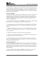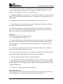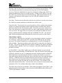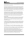
1
USER MANUAL
TM
© Associated Research, Inc., 2009
13860 West Laurel Drive
Lake Forest, Illinois, 60045-4546 U.S.A.
S8456
Item 38362
Ver 1.14
Printed April 10, 2009
TABLE OF CONTENTS
INSTALLATION PROCEDURE .................................................................................1
MAIN START UP WINDOW ......................................................................................2
SETUP SYSTEM PARAMETERS...............................................................................3
Auto-Configuration ...................................................................................................3
Primary Unit ............................................................................................................10
620LUnit........................................................................................................................1
2
Calibration ...............................................................................................................12
Print Settings ...........................................................................................................13
Security ....................................................................................................................16
Auto Load Parameters ............................................................................................18
Demo Parameters.....................................................................................................19
Barcode Scanner......................................................................................................20
Remote Scanners .....................................................................................................21
Startup .....................................................................................................................22
FILE MANAGER........................................................................................................27
SETUP TEST PARAMETERS...................................................................................30
RUN TESTS ................................................................................................................40
REMOTE DATA LOGGING .....................................................................................43
EXAMINE STATISTICS............................................................................................45
INSTALLATION
This instrument control software was designed to provide you with a quick and easy way
to utilize RS232 or GPIB (IEEE-488.2) when using Omnia 8004, 8005, 8006, 8104,
8105, 8106 and 620L. It offers you complete control of the instrument setups as well as
the ability to capture test results. This manual will provide complete operating
instructions. The Help Windows within the software offer the same procedures as this
manual.
SYSTEM REQUIREMENTS
• National Instruments GPIB interface card (Not needed with RS232)
• GPIB connection cables (Not needed with RS232)
• One available serial port (two with remote scanner) (Not needed with GPIB)
• Microsoft Windows 9x, 2000, XP or Windows NT
• PC with Pentium Processor
• CD-ROM drive
• 32 MB RAM minimum, 64MB recommended
• 40 MB free disk space on your hard drive
INSTALLATION PROCEDURE
1.
Insert the Autoware compact disk into your CD ROM drive. A Readme.txt file is
also available in the root directory of the CD with additional install information.
2.
Select the Run command from the Start menu.
3.
Click the browse button and select the CD ROM drive.
4.
Double click or run the program called Setup.exe within the S8456 subdirectory.
5.
Follow the instructions within the Setup Program window for a complete
installation.
Please note: The National Instruments Visa driver and runtime engine will automatically
be installed on your system during the installation of Autoware. Autoware will not run
without these programs.
6.
7.
After installation is complete an “Associated Research Autoware”program group
will be created with an icon labeled Autoware S8456 Click on the icon to run the
software.
When the software is first initialized a message to will prompt you to first select
the security mode. Then you should go to the Primary unit page to set the
communication parameters.
1
MAIN WINDOW
MAIN START UP WINDOW
Main Menu window Autoware S8456
Two Pull down selection in the menu bar are File and Window. The Window pull down
menu consists of the 6 selections that will access 6 different windows that are described
below. The window pull down menu is also duplicated on all of the windows that are
accessible from the Window menu. Therefore direct access to any one of these windows
is available after one of the windows has been selected.
Setup System Parameters: This window is used to setup communication between
Autoware and the PC. These software configuration windows do not require
communication with the actual test instrument(s). The remote indicators on the
instruments may not light during these setups.
File Manager: This window is used to manage the setup files. You can work with files
stored in the instrument memory or in the PC memory.
Setup Test Parameters: This window is used to setup and store test parameters as well
as recall test setups from existing files.
Run Tests: This window allows you to initiate and reset tests. You will also be able to
monitor results of the test. You can also use barcode scanning and load files from this
window.
Remote Data Logging: This window primary use is to start test remotely whiles saving
test results to a file on the computer. There is no ability to start the test from this window
through the computer interface.
Examine Statistics: This window allows you to see actual test results and graph results
by category.
2
SETUP SYSTEM PARAMETERS
SETUP SYSTEM PARAMETERS
This window will automatically be started when you first install the software. The first
option on this window is titled "Instruments Configuration". This control allows you to
select which instruments you wish to control. The software defaults to configuration one.
This control is used to select different combinations of instruments and system settings to
tailor your testing environment for different situations. You can scroll through the
configurations by clicking on the up/down arrow and the display window will indicate
which instruments are configured for that configuration number. You are allowed to have
up to 999 different configurations.
There are 10 tabs on this window that will take you to a different page of system settings.
The tabs are labeled; Primary unit, 620L unit, Security, Bar Code, Auto File Loading,
Calibration, Print, Demo, Remote Scanners, and Startup. There is also an AutoConfiguration button located by the Instrument Configuration menu. Please refer to the
following sections for descriptions of the parameters on each page.
Auto-Configuration
The Auto-Configuration feature allows Autoware to automatically scan the PC for active
serial, GPIB ports or Ethernet addresses. Using this button will allow Autoware to scan
the network for Associated Research, Inc. testers compatible with the Autoware S8456
software.
If the Auto-Configuration button is pressed, Autoware will first initialize the scan. The
Configuration Progress field at the top of the screen will display the following:
“Preparing… Please Wait”.
The software will first start to scan for primary units. The Configuration Progress field will
then display the following: “Scanning for Primary Unit… ”
3
SETUP SYSTEM PARAMETERS
If a primary unit is found, the Configuration Progress field will display the following:
“Scanning for Primary Unit… Unit Found: Unit Found: Serial/USB, Address X”
where “X”is the value of the serial port. The Omnia also supports GPIB and Ethernet
communications.
If a primary unit is not found upon scanning, the Configuration Progress field will display
the following: “Scanning for Primary Unit… No Unit Found”.
4
SETUP SYSTEM PARAMETERS
In the event that more than one primary unit is connected to the PC, Autoware will display
a warning message: “Multiple Primary Units were found at the following locations.
Please select which unit you would like to use for this instance of Autoware”. The
prompt will display the connection type (Ethernet, GPIB or Serial), address for that
connection type and the serial number of each unit.
Select the correct primary unit and hit OK. Only one primary unit may be selected at a
time.
The primary unit will then automatically be setup with the proper Communication Type,
Address/Com Port, Type of Unit, Serial Number and Calibration Due Date information.
The Auto-Configuration will then scan for 620L units. The Configuration Progress field
will then display the following: “Scanning for 620L… ”
5
SETUP SYSTEM PARAMETERS
If a 620L is found, the Configuration Progress field will display the following: “Scanning
for 620L… Unit Found: Serial/USB, Address X”where “X”is the value of the serial
port. The 620L also supports GPIB and Ethernet communications.
If a 620L is not found upon scanning, the Configuration Progress field will display the
following: “Scanning for 620L… No Unit Found”.
6
SETUP SYSTEM PARAMETERS
In the event that more than one 620L is connected to the PC, Autoware will display a
warning message: “Multiple 620Ls were found at the following locations. Please select
which unit you would like to use for this instance of Autoware”. The prompt will
display the connection type (Ethernet, GPIB or Serial), address for that connection type
and the serial number of each unit. Select the correct 620L and hit OK. Only one 620L
may be selected at a time.
The 620L will then automatically be setup with the proper Communication Type,
Address/Com Port, Type of Unit, Serial Number and Calibration Due Date information.
The Auto-Configuration will then scan for Remote Scanners. A Remote Scanner is an
Associated Research, Inc. SC6540 master scanner unit. The Configuration Progress field
will display the following: “Scanning for Master SC6540 Units… ”
If an SC6540 master scanner is found, the Configuration Progress field will display the
following: “Scanning for Master SC6540 Units … 1 Found: Please configure scanner
7
SETUP SYSTEM PARAMETERS
channels below”. The master SC6540 unit must then be configured with the proper
number of high voltage and/or high current channels.
The software does allow for multiple master SC6540 units. In the event that multiple
master SC6540 units are connected to the PC, the Configuration Progress field will
display the following: “Scanning for Master SC6540 Units… X Found: Please
configure scanner channels below”where “X”is the number of master SC6540 units
found. Channels for all scanners must be configured.
If a master SC6540 unit is not found upon scanning, the Configuration Progress field will
display the following: “Scanning for Master SC6540 Units… No Unit Found”.
8
SETUP SYSTEM PARAMETERS
If a scanner becomes disconnected at any point, the Auto-Configuration feature will warn
the user upon initialization:
Auto-Configuration will allow the user to continue with a full normal scan, continue
scanning for primary units only or cancel and exit back to Setup System Parameters.
NOTE: Auto-Configuration is only compatible with SC6540 scanners with firmware
V1.01 and above.
Once Auto-Configuration has finished scanning for all units the Configuration Progress
field will display the following: “Scan Complete”.
9
SETUP SYSTEM PARAMETERS
Primary Unit
This set of parameters is used to setup the communication to the hardware. If you select
the tab labeled Primary Unit you will see the settings shown below.
Primary Unit page
Enable Omnia Type: The Omnia units and 620L unit can operate as a system or
independently from one another. This box must be checked to incorporate an Omnia unit.
View available communication connection key: This key can be used to have the software
search for the communication ports that are configured on the computer. You will see a
list of ports to choose from. After selecting one of them the values will be entered in the
fields for Communication Type and Address/Com Port.
Communication Type: Four options are available here, Ethernet, Serial (RS-232), GPIB
or Demo. Select the type of communication protocol you are using. If GPIB is selected
then be sure you have installed a properly configured GPIB card in your PC. If you select
10
SETUP SYSTEM PARAMETERS
Serial (RS-232) be sure you have an active and properly connected Serial Port on your
PC. If you select Ethernet, be sure that your network connection on the PC is active and
working properly and the Ethernet cable is properly to the network. You may need a
different style cable depending on whether you connect to the network or directly to a PC
only. Demo mode doesn't require a communications protocol to be set. It has limited
functionality and is intended to demonstrate some of the basic functions of this software.
Address/Com Port: Address refers to the GPIB address of the instrument you are
controlling. Valid GPIB addresses are 1-30. You may control up to 14 instruments using
a single GPIB card but each instrument must have a unique address. Com Port refers to
the setting of a serial device. Normal serial port addresses for Com Ports are numbers 14. A single Com Port may control only one instrument.
Ethernet Address: When Ethernet is selected the Address /Com Port field will change to
the Ethernet Address field. This is the Ethernet Address of the instrument you are
controlling. That address could have been acquired manually or automatically through the
network DHCP server. If configured automatically be sure to check with you system
administrator to be sure that the instrument address will be reserved and continue to
remain the same to prevent communication errors. If the server assigns a new address to
your instrument you will need to revise the Ethernet Address field to match the
instrument.
Read configuration from the instrument key: This key can be used to have the software
communicate to the instrument and automatically configure the various fields that are
indicated in this section of the screen. After pressing the key the values will automatically
be entered into the appropriate fields. If the system detects that you are using local
scanner you will be required to select the correct scanner type.
Type of Unit: Valid instruments that work include 8004, 8005, 8006, 8104, 8105, 8106
and 620L. Please select which instrument you wish to control.
Serial Number: The serial number of the test instrument can be used for ID purposes on
test results data, printing and calibration due date checks. Enter the serial number from
the serial number plate on the test instruments if you would like Autoware to use it.
Calibration Due Date: You can enter the calibration due date for the instrument if you will
be using the Calibration Alert Utility or if you would like the date to show on hard copy
print outs.
Scanner : There are three possible selection. 1 x 8 Channel Scanner (internal or external),
2 x 8 Channel Scanners (can be one internal and one external or two external scanners), or
None. Select the scanner setting that matches your hardware configuration.
DUT-HV Setting: This selection is only visible when model 8005, 8006, 8105 or 8106 is
selected. This field is used to activate the ability to control the HV that is applied to the
11
SETUP SYSTEM PARAMETERS
Line and Neutral connectors of the DUT Outputs on model 8005, 8006, 8105 or 8106.
When this field is checked the HV Output selection on the Setup Test Parameters window
will be enabled for HV test types ACW, DCW, and IR. When it is left unchecked the HV
Output selection will not be visible on the Setup Test window. NOTE: This selection
will not change the System Setting in the Hardware menu on the Omnia hardware. If this
function is required be sure that the hardware is configured to match the selection in this
window. If the selection does not match the hardware then errors will occur when saving
files to Omnia.
620L Unit
This set of parameters is used to setup the communication to the hardware. If you select
the tab labeled 620L unit you will see the settings shown below.
620L Unit page
Enable 620L Type: If you are using a system, this box must be checked to control a 620L
unit. The Omnia units and 620L unit can operate as a system or independently from one
another.
The 620L unit tab has the same parameters as the primary unit tab. The device control is
set through available communication connections, Communication Type, Address/comm
port, Ethernet address, Read configuration from instrument key, Type of unit (620L unit is
the only option), Serial Number, Calibration due date and scanner control. NOTE: The
620L unit does not have the capability to enable the DUT-HV setting.
Calibration
The calibration due date for the test instruments can be checked each time that the
software is started. The "# of days to warn" field is used to select the number of days
prior to calibration due date that the software will prompt you that the instrument is due
for calibration. The calibration warning message can only be cleared by a user that has
12
SETUP SYSTEM PARAMETERS
Full System Access security rights, so that management personnel will be aware of the
calibration due information.
The prompt will only be shown one time until the calibration is out of date. When the
calibration date is equal to or past the due date the prompt will occur after the software is
started and one of the operation windows begins to load. The warning is always relative
to the instruments under control configuration that has been selected in Setup System
Parameters.
Print Settings
These settings allow you to configure a printed report for each device that has been tested.
The report will display all tests that were performed on a product with its model and serial
number, test instruments used, date and time, the operator or user identification, and the
setup parameters file name if one was used to configure the instrument.
The options here enable the “Auto Print”, “Print Failures Only”or “Print Test Settings”.
When "Auto Print" is selected a printout of test results will automatically be sent to the
printer at the conclusion of every test. If you wish to only have an automatic printout of
failures then in addition to selecting the "Auto Print" function you also need to select
"Print Failures Only". When “Print Test Settings”is selected all test settings are printed as
well as results for each step. The left page header, right page header and descriptions of
each test step will be displayed on the printout when something is typed into the respective
fields. The print tab is show below.
Print page
Enabling the print test settings option allows the user to add description to individual test
steps. These steps can be created and edited in the “Setup Test Parameters”window.
13
SETUP SYSTEM PARAMETERS
Setup Test Parameters screen with Step Description
Step descriptions can be added for each individual step in a test sequence and will be
displayed on the printout.
14
SETUP SYSTEM PARAMETERS
Print Preview of Expanded Report with Headers and Step Descriptions Included
If you wish to have an automatic printout of test settings then in addition to selecting the
"Auto Print" function you also need to select "Print Test Settings". If you wish to only
have an automatic printout of failures with associated test settings for failed steps, then in
addition to selecting the "Auto Print" function you also need to select "Print Failures
Only". This will send a printout of test failures only to the printer at the conclusion of the
test. If multiple tests are linked together and any one test fails the "Print Failures Only"
function will print all steps of the test including those that may have passed because the
system sees this test sequence as one test. To view the contents of this report a print
preview menu item is available on the Run and the Remote Data Logging windows.
15
SETUP SYSTEM PARAMETERS
Security
If you select the tab labeled Security you will see the settings shown below.
In this window, you can view the list of users that are setup and their security level. Only
users with Full System Access can enter the Setup System Parameters window when
security has been enabled. The security will be turned on when the check box near the top
of the page labeled Security Mode On has been selected. After changing the Security
Mode, be sure to save the changes.
Edit User Detail: New users will be added in this window. Existing users may also be
edited here using the "Edit" key. If you wish to enable security then you must check the
box at the top of the panel, "Security Mode On". When adding a new user you click on
the Add New User key. The window shown below will open.
Enter an alpha/numeric User ID, Password, Password Confirmation and desired security
level. There are four security levels to choose. Run Only, Edit Setups, Recall Setups and
Full System Access.
Run Only: This is the most restricted mode of user access. The user can only initiate a
test, reset a failure or abort a test.
16
SETUP SYSTEM PARAMETERS
Recall Setups: This mode allows the user to recall previously configured test setups but it
does not allow any editing of the parameters. In this mode the user is restricted from
access to the "Setup Test Parameters" window.
Edit Setups: In this mode the user can recall and edit test parameters.
Full System Access: In this mode the user has full access level to all instrument setup
parameters as well as software configuration and security levels. Access at this level
should be restricted to System Administrators.
17
SETUP SYSTEM PARAMETERS
Auto Load Parameters
If you select the Tab labeled “Auto File Loading”you will see the settings shown below.
These settings allow the operator to automatically load and edit setup files by associating
the test parameter setup files to a model number. You must have already created the setup
file using the Setup Test Parameters windows before you can make the association. When
a model number is typed or scanned with a bar code scanner then the setup file would be
automatically loaded if it were not already loaded.
This window shows a list of all associations and allows access to a sub-level windows to
make changes to the association. The association feature can be enabled or disabled by
selecting the check box at the top of the page. The check box must be enabled for the
auto loading to occur on the Run or the Remote Data Logging windows.
Another feature of Auto File Loading is the ability to require a valid model number to
enable the Test button. This assures that tests will only be performed on models that have
valid test programs loaded to the RUN window before tests can be performed. If the
model entered on the RUN test window does not have a valid association to a setup file
then a pop-up warning message will appear if the Test button is pressed. To enable this
feature check the "Configuration Required to Execute Test" box. This field does not have
any effect in the Remote Data Logging window since the tests are started remotely and
Autoware does not control the starting of tests in that window.
Use the Export to File button to export the list of associated model number and setup file
names to a file. The file created is a standard ASCII file with TAB delimited columns.
This file can be used to print or edit the information from spreadsheet or word processing
programs such as Microsoft Excel or Word.
18
SETUP SYSTEM PARAMETERS
You can create a new model association or click on the delete key to cancel an association
after you have highlighted the appropriate selection. To change an association for specific
model you must first delete the association and then create a new one by adding a new
model.
Add New Model button: Clicking on this button will launch the window shown below.
First type in the model number then click on "Specify Setup File Path" key. A pop up
window will appear to select the file. Select the file then click the OK key on the popup
window. Verify that the correct path is shown in the path window then click the OK key
to complete the association.
Demo Parameters
If you select the Tab labeled Demo Parameters you will see the settings shown below.
When "Demo" mode is selected in the "Communication Type" settings of the instrument
ID, several additional parameters may be set. You may check "All Tests will Pass" which
will simulate the passing of all DUT's tested or you may set a % of tests to FAIL. When
executing tests in the demo mode the test results will be controlled by these two
parameters. If "All Tests will Pass" is selected then the Percent Failures value will be
ignored and all test results will indicate Pass.
19
SETUP SYSTEM PARAMETERS
When "All Tests will Pass" is not selected then the program uses the Percent Failure value
to generate an approximate failure rate based on this number. For example; if the percent
failure value is 20%, 2 out of 10 tests will generate a failure result.
Barcode Scanner
If you select the Tab labeled Barcode Scanner will see the settings shown below.
Barcode Scanner Setup window showing concatenated barcode setup
If you desire to use a barcode in your system to capture Model or Serial numbers with
your test results data you will need to setup the barcode format on this page. Other
features can also be configured here such as using single or multiple barcodes or to require
a barcode input before tests can be performed.
These settings are used to configure your barcode data. Two fields can be setup as
barcode input. They are the DUT Model Number and Serial Number. The configuration
can be set to scan one of the two or both inputs. They can also be separate barcodes or
one single concatenated barcode containing both fields.
To activate the barcode scanner, first select Model Number, Serial Number or both of
them from the "Barcode Fields" section. If you are using both barcodes then also select
which one you would like to scan first from the "First Field" selection. This selection
also determines the order of the fields when using the concatenated barcode configuration.
To use a single concatenated Barcode containing Model and Serial numbers, check the
"Single Concatenated Barcode" selection from the "Single Barcode" area. After selecting
this configuration, two other fields become available, "# of Characters in First Field" and
"Delimiter Character". If your barcode does not have a special character or characters to
separate the Model and Serial number fields then simply enter the number of characters
20
SETUP SYSTEM PARAMETERS
that represents your first field. The remaining characters in the barcode will be used for
the second field.
If your barcode uses a character separator or delimiter then set the "# of Characters in
First Field" equal to "0" and enter the delimiter character in the "Delimiter Character"
field. The first field will use all of the characters before the delimiter character and the
second field will use all characters after the delimiter.
Another feature of the barcode configuration is the ability to require a barcode data input
to enable the Test button. This assures that the Model and/or Serial numbers will be
recorded along with the test results for printing or data storage functions. To enable this
feature check the "Barcode Required to Execute Test" selection in the "Barcode Fields"
area. This field does not have any effect in the Remote Data Logging window since the
tests are started remotely and Autoware does not control the starting of tests in that
window.
Remote Scanners
If you select the Tab labeled Remote Scanners you will see the settings shown below.
When your system includes one or more Remote scanners, use this screen to select the
type of Scanner, the Serial, GPIB or Ethernet communication type, and the GPIB address,
serial communication port number or IP address. For model SC6540 you must also
configure the number of scanner channels installed in the system.
In this screen you can select the appropriate number of remote scanners that you will
include in your system and then define the communication parameters for each. First enter
the number of remote scanners in your system into the "Number of Remote Scanners"
field. After the number is entered, the communication configuration fields will appear.
21
SETUP SYSTEM PARAMETERS
First select either SC6540 or HS-16 model numbers under the scanner type field for each
additional remote scanner. Then select one of the three communication types, GPIB,
Serial, Ethernet or Demo mode. In Demo mode you will be able to run the software
without having any instrument connected to the system. Next, enter a valid number in the
Address / Comm Port field for the appropriate communications type that you have
selected.
If the scanner has Ethernet communication protocol, the “Show Scanner ID”button can
be used to display the scanner’s dip switch configuration. This makes it easier to keep
track of various scanners on a network.
If you have scanner model SC6540 configured in the system then also enter the number of
HV and/or GND channels that will be controlled from that communication port, and then
click OK to save the configuration. The scanner configuration will be saved within the
system setup file along with communication parameters for the other test instruments in
the system.
Startup
If you select the Tab labeled Startup you will see the setting shown below.
This setting allows the user to configure the software to start in a specific window when
the software is initially loaded.
File Menu
Save: Select this menu item to Save the configuration. All of the settings within each page
will be saved together under the configuration number. When the program is started it
will use the same configuration that you were using when it was last closed.
Save and Close: This selection will save the settings and then exit to the Main window.
22
SETUP SYSTEM PARAMETERS
Auto-Configuration: This selection will initiate the Auto-Configuration feature and will
scan for any units connected to the PC. See the Auto-Configuration description at the
beginning of this section for details.
I/P Settings Editor: This editor menu can be used to keep track of multiple units
connected to a network. There are three fields at the top of this editor that are associated
with the PC settings: This Computer’s I/P Address, This Computer’s Subnet Mask and
This Computer’s Default Gateway. This will show the user the settings of the associated
PC. The image below illustrates the I/P Settings Editor window:
Below the computer settings, the I/P Settings Editor displays all the models connected to
the network. Each model has a displayed I/P Address, MAC Address, Company
(Associated Research, Inc.), Model, Serial Number and Firmware. For example:
I/P Address: 192.168.1.45
MAC Address: 00-22-4A-E0-7D-49
Company: Associated Research, Inc.
Model: SC6540
Serial Number: 1234567
Firmware: V2.00
This feature is also helpful for keeping track of multiple master SC6540 scanners. Since
the scanners do not have a display, they have no indication on whether or not they are
communicating with the network. This feature allows the user to keep track of all scanners
by serial number, I/P address, MAC address and dip switch configuration. If a scanner is
highlighted, the dip switch configuration will appear on the top right hand side of this
screen along with the dip switch binary value. This allows the user to keep track of
multiple master scanners by the value of the dip switches.
23
SETUP SYSTEM PARAMETERS
If two scanners have the same dip switch configuration, the user will be warned and
Autoware will recommend that the configuration be changed to the next available decimal
value:
A unit can also be edited by using the SCAN, CHANGE I/P and RECOVER USING
MAC buttons located at the bottom of the I/P Settings Editor screen. The user can also
receive information about the I/P Settings Editor with the HELP button.
SCAN: Pressing this button will initiate a full scan of the network. Any units
connected to the network will then be displayed on this screen.
CHANGE I/P: This feature will allow the user to manually change the I/P address
of a unit on the network. The user must first highlight a unit on the network to use
this feature. If a unit is highlighted and this button is pressed, the ADDRESS I/P
ENTRY window will prompt the user: “Please enter the new I/P address. Entering
0.0.0.0 into the Subnet Mask or Default Gateway field will reinitialize the default
value.”The user can then enter a new I/P address for the instrument. If the user
24
SETUP SYSTEM PARAMETERS
would like the DHCP server to automatically scan for available I/P addresses, the
AUTO button at the bottom of the screen must be checked. Press OK to save the
changes. Press CANCEL to exit this window without saving the changes.
RECOVER USING MAC: If a unit on the network cannot be found via a system
scan, the user can attempt to find the unit using this feature. If the user hits the
RECOVER USING MAC button, the program will display a window with the
following message: “Please Enter the MAC address of the Associated Research
Unit you wish you recover. The MAC address is located inside the unit in 00-204a-xx-xx-xx format.”The user can type the MAC address of the associated unit
into the MAC Address field and hit OK to attempt a recovery of the instrument.
Press CANCEL to exit this window without saving the changes.
HELP: Pressing this button will display information about the I/P Settings Editor
and its features.
25
SETUP SYSTEM PARAMETERS
BACK: Pressing this button will return the user to the SETUP SYSETM
PARAMETERS window.
Window Menu
The Window pull down menu consists of the 6 selections that will access 6 different
windows that are described below. The window pull down menu is also duplicated on all
of the windows that are accessible from the Window menu. Therefore direct access to any
one of these windows is available after one of the windows has been selected.
Setup System Parameters: This window is used to setup communication between
Autoware and the PC. These software configuration windows do not require
communication with the actual test instrument(s). The remote indicators on the
instruments may not light during these setups.
File Manager: This window is used to manage the setup files. You can work with files
stored in the instrument memory or in the PC memory.
Setup Test Parameters: This window is used to setup and store test parameters as well as
recall test setups from existing files.
Run Tests: This window allows you to initiate and reset tests. You will also be able to
monitor results of the test. You can also use barcode scanning and load files from this
window.
Remote Data Logging: This window primary use is to start test remotely whiles saving
test results to a file on the computer. There is no ability to start the test from this window
through the computer interface.
Examine Statistics: This window allows you to see actual test results and graph results by
category.
26
FILE MANAGER
FILE MANAGER
The File manager window serves two functions
1. View and organize existing files in Omnia and in the computers memory.
2. Perform batch execution to configure Omnia’s memory.
The file menu is divided into two main sections. The left side is used to manage the files
and the right half is used to configure a batch process. When Enable Batch Processing is
not selected in the menu, the Omnia Batch table will be disabled and grayed out.
The menu selections for file managing are Save As, Rename, Delete. To use these menu
selection first select the file you want to work with from the Files list and then select the
menu item from the File menu.
Batch Processing
When the Enable Batch Processing menu items is selected the Omnia Batch table will be
enabled a s shown below.
Batch Processing is a function used to organize and copy files to Omnia and 620L in a
single step routine. Once the batch is enabled through the menu the file managing menu
functions will be disabled.
When you enable the batch process you will notice the Batch table will be enabled and it
will initially show the list of existing files in Omnia’s memory. All of the pending changes
that are configured in the Omnia Batch table will be indicated in the Action column of the
table. Be sure to review the list before executing the batch. The menu items found in the
batch section of the file menu will be used to configure the batch process. The batch menu
items are described in the following section.
Enable Batch Processing: Select this item to start Batch configuration.
Execute Batch: Once the batch is configured in the Omnia Batch table, select this function
to update Omnia memory.
27
FILE MANAGER
Replace Omnia File: This function will delete the file selected in the Omnia Batch table
and replace it with the file selected on the File list. A window will open that will also
allow you to change the name if desired or you can keep the original name. The action for
this file will indicate Replace.
Insert to Omnia: This function is used to insert the file selected on the File list into the
Omnia Batch table. The new file will be inserted at the location that is highlighted in the
Omnia Batch table. The file already at this location and all files below it will move down
one position. The action for this file will indicate Insert.
Delete from Batch: Use the Delete function to delete files from Omnia’s memory. Select
the files on the Omnia Batch table on the right side of the window and select Delete from
Batch from the batch section of the File menu. The action for this file will indicate Delete.
Rename: This function will leave the file parameters unchanged but give the file a new
name. Select the files on the Omnia Batch table on the right side of the window then
select Rename from the File menu. A dialog window will open to allow you to type in the
new name. The new name will be shown in the Omnia Batch table and the action for this
file will indicate Rename.
Once the batch configuration is setup then Select Execute Batch from the menu to send all
files to Omnia. The File list on left side should update with all the new files that are
configured in Omnia’s memory when Omnia (live) is selected from the directory list.
Window Menu
The Window pull down menu consists of the 6 selections that will access 6 different
windows that are described below. The window pull down menu is also duplicated on all
of the windows that are accessible from the Window menu. Therefore direct access to any
one of these windows is available after one of the windows has been selected.
Setup System Parameters: This window is used to setup communication between
Autoware and the PC. These software configuration windows do not require
communication with the actual test instrument(s). The remote indicators on the
instruments may not light during these setups.
File Manager: This window is used to manage the setup files. You can work with files
stored in the instrument memory or in the PC memory.
Setup Test Parameters: This window is used to setup and store test parameters as well as
recall test setups from existing files.
Run Tests: This window allows you to initiate and reset tests. You will also be able to
monitor results of the test. You can also use barcode scanning and load files from this
window.
28
FILE MANAGER
Remote Data Logging: This window primary use is to start test remotely whiles saving
test results to a file on the computer. There is no ability to start the test from this window
through the computer interface.
Examine Statistics: This window allows you to see actual test results and graph results by
category.
29
SETUP TEST PARAMETERS
SETUP TEST PARAMETERS
Setup Test Parameters window
The Setup Test Parameters window is where you will build the test or sequence of steps
that will be used to perform tests in the Run Window.
Creating test programs
To build the files first choose the group of parameters for the test you want to perform by
selecting the tab at the top of the parameters section. Once the test type is selected add it
to the step list by using the insert function from the edit menu. To add more steps, select
the next available blank step on the list and insert additional tests. NOTE: All Omnia and
620L tests steps must be grouped together by each respective unit. For example, the
system will not accept a test sequence that starts with an Omnia hipot test then switches to
a 620L line leakage test and then back to an Omnia test. The test parameters for each step
can be reviewed or edited at any time by selecting the step from the step list and the
parameters will automatically be displayed.
The edit menu contains other functions for creating and editing the test program they
include Delete, Delete All, and Replace.
Delete: Deletes the step that is selected
Delete All: Deletes all the steps in the file.
Replace: Replaces the step that is selected with the new step.
30
SETUP TEST PARAMETERS
Additional parameters that are associated with the entire test file (as apposed to each step)
are located in the File Parameters menu. The Data file should be selected if you desire to
store these results in a data file on the computer. Once you have selected this option you
will be prompted for the data file name which can be created or an existing one can be
selected. Also confirm that the Fail Stop Selection is correct. See the section on the File
Parameters menu for more detail.
File creation Example:
On Omnia model 8004 or 8104 there are five different types of tests you can perform: AC
Withstand (ACW), DC Withstand (DCW), Insulation Resistance (IR), Ground Bond
(GND) and Continuity (CONT). For our example we will run a Ground Bond test first,
then an AC Withstand test and finally an IR test. We want to run these three tests in
sequence and automatically.
1). Be sure that the first step on the list is highlighted. Using the mouse, click on Ground
Bond (GND) tab. This will bring up the "GND Test Parameters" page.
2). Set your parameters for the Ground Bond Test on the right hand side of the window.
Go to the Edit menu and select Insert . You should see a summary of the test at step
number 1.
3). Highlight step number 2 in the step list. Now click AC Withstand (ACW) tab with
your mouse. Go to the Edit menu and select Insert . You should see a summary of the
test at step number 2.
4). Repeat the same sequence of steps for the IR test for step number 3.
5). You can review each step’s parameters now by clicking the desired step on the step
list. Edit the parameters as desired for each step.
6). When all the changes are correct then save the file by selecting Save from the file
menu. You can either save the file directly to Omnia or save it to the PC to be later sent
to Omnia when testing will be done.
File creation Example #2:
On 620L model there are two different types of tests you can perform: Line Leakage
(LLT) and Functional Run (Optional). However, the Omnia series can be used in tandem
with the 620L unit. For our example we will run a series of line leakage tests from the
620L and two ACW tests from the Omnia 8104. We want to run these tests in sequence
and automatically.
1). Be sure that the first step on the list is highlighted. Using the mouse, click on AC
Withstand (ACW) tab. This will bring up the "ACW Test Parameters" page.
31
SETUP TEST PARAMETERS
2). Set your parameters for the AC Withstand Test on the right hand side of the window.
Go to the Edit menu and select Insert. You should see a summary of the test at step
number 1. Repeat number 1 and 2 for the next ACW test.
3). Highlight step number 3 in the step list. Now click Line Leakage (LLT) tab with your
mouse. Go to the Edit menu and select Insert . You should see a summary of the test at
step number 2.
4). Repeat the same sequence for the remaining line leakage tests as in step 3.
5). You can review each step’s parameters now by clicking the desired step on the step
list. Edit the parameters as desired for each step.
6). When all the changes are correct then save the file by selecting Save from the file
menu. You can either save the file directly to Omnia or 620L or save it to the PC to be
later sent to Omnia or 620L when testing will be done.
File Menu
Open: This item opens setup files for editing.
1). Go to the File menu and click open.
2). The FOLDERS window will open showing your last path and files. Select the drive,
path and file you wish to load from memory, you can also select Omnia and load a file
from its memory. You can select the file to get a quick preview of the steps in the file
before loading it.
3). Click on OK. Once this process is complete can edit the setup and save it then you
may go to the Run window and run your test.
Save: If you wish to permanently save your setup to a file that can be recalled and used to
automatically setup the instrument in the future, then do the following:
1). After the setup is complete click Save from the File menu.
2). You will be asked to select a file name and a path to store the setup file. We suggest
you give the setup a name that reflects the product or products you are testing or a setup
sequence number. We also suggest you store all your saved setups in a similar file format,
extension and directory.
3). Click on OK. The setup is then saved and stored.
File Parameters Menu
The settings will be saved within the file and are relative to the whole test process an not
just an individual step. These settings are only visible through the menu.
32
SETUP TEST PARAMETERS
Fail Stop: The Fail Stop selection is found in the File Parameters menu pull down. When
in the checked position the test will stop at the step where a FAILURE condition
occurred. If there are unfinished test steps to be performed, clicking on the "TEST" key
again will continue the test process to the next step. Clicking on the "RESET" key then
the "TEST" key will start the process from the first step. When unchecked the test will
continue to the final step of the sequence even if a FAILURE condition occurs in a
previous step.
Save Data: This box must be checked in order for test results to be saved to your chosen
file. If this box remains unchecked no data from tests will be saved.
Select Data File: If you wish to save your test results to a file to examine in the statistics
window or to import into another software application then you should check the box
titled, Save Data from the File Parameters menu. Then click your mouse on the File for
Data. This will open up a window that will let you name a path, directory and file to save
your test results. We suggest that you keep all your test data files in similar directories
and use a similar format for naming the files such as PRODUCTA.TXT. The selected
path will then be displayed in the information box on the lower portion of the window.
Other Window Options
CONTINUITY: When this box is checked you are instructing the software to perform a
low current (0.1 Amp) check on the DUT’s ground system while the HV test is being
processed. The Ground Continuity test is functional in the AC and DC Withstand test
mode of Omnia. The ground continuity check cable must be connected to the chassis of
the DUT. If the DUT's ground system does not have continuity, the software will indicate
a continuity failure when the "Test" key is activated. Under this condition high voltage
will not be activated.
AUTO OFFSET: "Auto Offset" enables you to offset the resistance in your test leads
and/or fixture when performing a Ground Bond test. Since the measured value during the
GND test is typically very low, it is important to measure only the resistance of the DUT.
When checked you are instructing the software to measure the resistance of your test
leads and/or fixture and use the measured value as the offset value for a particular memory
and step. A different value may be measured and used for each step in a memory. You
must connect your test leads and/or fixture to the instrument and short them together.
Then select Save from the file menu and save the file to Omnia. The resistance of the
leads and/or fixture will be offset. The auto offset value can only be viewed locally on the
instrument's LCD. The available offset range is from 0-200 milliohms.
The offset value can also be set manually. This is done by setting the "Auto Offset" to the
unchecked position and entering a value of between 0-200 milliohms under Offset in the
"GND Test Parameters" window.
33
SETUP TEST PARAMETERS
50Hz/60Hz: This allows you to select an output frequency of 50 or 60Hz during an ACW
test or Ground Bond test so you can match the frequency at which the DUT is normally
operated. Point the cursor in this box and click your mouse to toggle between 50/60 Hz.
RAMP HI: The patented "Ramp HI" feature is only available when performing the DCW
or IR test. By checking this box you can quickly ramp the instrument's voltage output
without suffering the normal nuisance tripping that is common in a DCW test due to the
DUT's charging current exceeding the normal HI-Limit current setting. This function is
only active during the ramp period. For a more detailed explanation of the Ramp-HI
function see the manual that came with the test instrument.
AUTO CHARGE-LO: The patented Auto “Charge-LO" feature is only available when
performing DCW or IR tests. By checking this box this function will indicate whether
your test leads are properly connected at the beginning of a test. When performing DCW
and IR tests a capacitive DUT will draw charging current when the output is activated.
The Auto Charge-LO function monitors this charging current looking for a minimum
current flow (approximately 1/2 of the total charging current). If the charging current is
lower than the Charge-LO setting, a failure will occur indicating that your test cables may
not be connected. To set the Auto Charge-LO function be sure that the output voltage
and ramp time have been set to the values that will be used for the final test and then
connect the test cables and/or test fixture between the instrument and DUT. Click on the
"Send Test Parameters and Load to Memory" key and the "Auto Charge-LO" will be set.
If a scanner is used be sure to set the correct scanner channels.
The Charge-LO current may also be set manually. This is accomplished by setting the
"Auto Charge-LO" to the unchecked position and entering a value between 0-350.0µA
under Charge-LO located in "DCW Test Parameters" window. Again, be sure that the
output voltage and ramp time have been set to the values that will be used for the final test
and then connect the test cables and/or test fixture between the instrument and the DUT.
Be sure to click on the "Send Test Parameters and Load to Memory" key to save the
setup. If a scanner is used be sure to set the correct scanner channels.
CONNECT: The "Connect" box is used to instruct the software to connect or link one or
more tests in sequence. If Connect is checked the next step in the sequence will be
executed. If Connect is unchecked the test sequence will stop at this step.
PROMPT: The Prompt Box is used to insert a pause within the test sequence. Type in
the message that will appear in a dialog box before the test executes. When the test is
started from the Run Tests window then the user will be given a dialog box with the
prompt message shown, before the actual test starts. The user must press the OK button
on the dialog box to clear it before the test will execute. When the user presses the OK
button the test will execute automatically.
ARC FAIL: An additional/optional setting for ACW and DCW is Arc Sense, which has a
range of 1-9. By checking the "Arc Fail" box you are activating a very sensitive Arc
34
SETUP TEST PARAMETERS
Detection System capable of detecting arcs of very short duration down to 10 microamps.
For more information on ARC Detection see the Operations Manual, FAQ's, or visit AR's
Web Site at http://www.asresearch.com.
DUT Output: This selection is only visible when the HV Output Setting selection field is
checked on the Setup System Parameters window. It will show for test types ACW,
DCW, and IR for models 8005 or 8006 only. This field is used to control the HV that is
applied to the Line and Neutral connectors of the DUT Outputs on model 8005 and 8006.
When it is enabled HV will be applied to the output during the test, if it is left disabled
then HV will not be applied during these tests and must be applied through another source
such as internal or external HV scanners.
Continuous: This selection is only visible when the 620L unit is enabled in the Setup
System Parameters window. It will show for test types LLT and RUN for model 620L
only. This field is used to control the power applied to the DUT during line leakage or
functional run tests. It allows the DUT to remain powered up in between separate line
leakage test steps. In this way, the DUT will not shut down in between line leakage tests.
If it is disabled then the DUT will power down in between each line leakage test.
Scanner Settings
The scanner can only be used on model 8004 or 8104 if an internal scanner was installed
at the factory or if external remote scanners were purchased to use with models 8005,
8006, 8105, 8106 or 620L. Contact Associated Research with questions concerning
scanner applications at 1-800-858-8378. Note: Scanners cannot be used to perform
RUNCHEK measurements.
To enable your 8 Channel scanner you must go to the Setup System Window and select
the scanner setting. The selections include one 8 Channel scanner (internal or external) or
two 8 Channel scanners (can be one internal and one external or two external scanners.)
Once selected a graphic representation of the scanner will appear at the bottom of the
Setup window.
Note: If your Omnia has a scanner module installed, you must configure it as such in
“Setup System Parameters”. If it is not, you will have problems sending test parameters.
If more than one scanner has been configured, you can choose each scanner from the
scanner selection list. Once selected, a graphic representation of the scanner channels will
appear to the right of the selection on the "Setup Test Parameters" screen.
The selected scanner will be visible and you will be able to change or view the channel
settings. The selector will show the 8 channel local scanners as well as all remote
scanners, but you can only view one scanner at a time from the "Setup System
Parameters" screen. If you desire to view all scanners at one time, select the "Set All
Scanners" menu item from the Edit menu. From this screen you will view the local
scanners and all remote scanners that have been configured in the system.
35
SETUP TEST PARAMETERS
Each of the outputs can be set as High (High Voltage, or Cont. Check), Low (Return) or
Open. For Line Leakage Testing (LLT), the scanner has been configured to use the
Continuity and Return input connectors of the scanner. These terminals may be used to
switch connection points such as the MD Probe-HI and Probe-LO leads. By clicking on
the colored box of the graphic representation you can setup each individual channel. To
set an output for High Voltage or Cont.Check, go to the desired channel and click the
mouse on the box. The box will turn RED; indicating a High output. To set an output for
Return go to the desired channel and click the mouse on the box twice. The box will turn
GREEN; indicating a Low position. When the box is BLACK the channel is "Open" or
inactive. Clicking the mouse multiple times will change the color from Black to Red to
Green and back to Black again in a continuous loop. Note: On scanner model HS-16 the
Continuity mode is configured to run through the HV matrix (not Ground Bond). This
mode requires special connections to be made to the HS-16.
For example, let's say that you want to set up the scanner and use the ACW test so that
upon activation it will test four different points on a DUT. This is what you would do:
1). After setting up the basic ACW test parameters, click the mouse on the box of the first
scanner channel. The box will turn RED; indicating a HIGH position. Do the same for
position 2-4. All four positions should illuminate red.
2). Save the file.
That's it! You have told the instrument to perform an ACW test that will activate four
high voltage channels on the scanner during the test. Be sure that you have properly
connected the test leads from scanner channels to your DUT or test fixture before
activating the test. See the operator’s manual that you received with your scanner for
connection information.
Note: The scanner setting for the Ground Bond test differs slightly than for the ACW,
DCW or IR tests. Because of the way a Ground Bond test makes its measurement, it is
not possible to activate several channels simultaneously as you can with high voltage
testing. The test operator can only choose to activate one output for each test setup.
When you select a Ground Bond test (GND) from the "Setup Test Parameters" window
the Ground Bond scanner settings will be visible. Here you may select "0" which is the
default that turns OFF all of the scanner channels, or you may select a number anywhere
from 1-8 if you have a single 8 Channel scanner or 1-16 for two 8 Channel scanners and
the HS-16 scanners or up to 80 channels for the SC6540. The number selected refers to
the output that will be active during the Ground Bond test. For example; if you select the
number 8 then channel 8 will activate and supply high current during the Ground Bond
test and all other channels will be open or inactive on that scanner.
CAUTION: When the system includes more than one remote scanner it is highly
recommended that only one scanner be active at any time for Ground Bond testing. The
Ground Bond test is performed at a given test current so if more than one output channel
36
SETUP TEST PARAMETERS
is active, then the current will split between these channels and you will not run a valid test
at the desired test current. You will not receive an accurate indication of the measured
resistance. Therefore check that only one scanner is configured for output and all other
scanners have the channel selection equal to "0".
Set All Scanners
If you desire to view all scanners at one time, select Set All Scanners from the Edit menu
the following window will open.
Setup All Scanners screen showing 12 Remote scanners
This screen will show the 8 channel scanners and all remote scanners that have been
configured in the system. This screen gives you the capability to view and edit all
configured scanners at one time. The 8 channel scanners are shown in the upper left-hand
corner and the balance of the screen is used to display the 12 possible remote scanner
setups. The screen has been formatted to display all 12 remote scanners at one time so
when using only a few scanners most of this screen will be blank.
The window will either display the HV scanner settings or the GND bond scanner settings
but not both at one time. This window displays the appropriate settings based on the Type
of Test that was selected in the Setup Test Parameters window.
When you select an ACW, DCW, IR, CONT or LLT tests from the Setup Test
Parameters window the High Voltage scanner settings will be visible. Each of the outputs
can be set as High (High Voltage, or Cont. Check), Low (Return) or Open. For Line
Leakage Testing (LLT), the scanner has been configured to use the Continuity and Return
input connectors of the scanner. These terminals may be used to switch connection points
such as the MD Probe-HI and Probe-LO leads. By clicking on the colored box of the
graphic representation you can setup each individual channel. To set an output for High
Voltage or Cont.Check, go to the desired channel and click the mouse on the box. The
37
SETUP TEST PARAMETERS
box will turn RED; indicating a High output. To set an output for Return go to the
desired channel and click the mouse on the box twice. The box will turn GREEN;
indicating a Low position. When the box is BLACK the channel is "Open" or inactive.
Clicking the mouse multiple times will change the color from Black to Red to Green and
back to Black again in a continuous loop. Note: On scanner model HS-16 the Continuity
mode is configured to run through the HV matrix (not Ground Bond). This mode requires
special connections to be made to the HS-16.
When you select a Ground Bond test (GND) from the Setup Test Parameters window the
Ground Bond scanner settings will be visible. Here you may select "0" which is the
default that turns OFF all of the scanner channels, or you may select a number anywhere
from 1-8 if you have a single 8 Channel scanner or 1-16 for two 8 Channel scanners and
the HS-16 scanners or up to 80 channels for the SC6540. The number selected refers to
the output that will be active during the Ground Bond test. For example; if you select the
number 8 then channel 8 will activate and supply high current during the Ground Bond
test and all other channels will be open or inactive on that scanner.
CAUTION: It is highly recommended that only one scanner be active at any time for
Ground Bond testing. The Ground Bond test is performed at a given test current so if
more than one output channel is active, then the current will split between these channels
and you will not run a valid test at the desired test current. You will not receive an
accurate indication of the measured resistance. Therefore check that only one scanner is
configured for output and all other scanners have the channel selection equal to "0".
Window Menu
The Window pull down menu consists of the 6 selections that will access 6 different
windows that are described below. The window pull down menu is also duplicated on all
of the windows that are accessible from the Window menu. Therefore direct access to any
one of these windows is available after one of the windows has been selected.
Setup System Parameters: This window is used to setup communication between
Autoware and the PC. These software configuration windows do not require
communication with the actual test instrument(s). The remote indicators on the
instruments may not light during these setups.
File Manager: This window is used to manage the setup files. You can work with files
stored in the instrument memory or in the PC memory.
Setup Test Parameters: This window is used to setup and store test parameters as well as
recall test setups from existing files.
Run Tests: This window allows you to initiate and reset tests. You will also be able to
monitor results of the test. You can also use barcode scanning and load files from this
window.
38
SETUP TEST PARAMETERS
Remote Data Logging: This window primary use is to start test remotely whiles saving
test results to a file on the computer. There is no ability to start the test from this window
through the computer interface.
Examine Statistics: This window allows you to see actual test results and graph results by
category.
39
RUN TESTS
RUN TESTS
Run Tests window
This window is where you will run your programmed tests. When you first enter this
window you will have the same file selected that you last set up in the Setup Test
Parameters window. Different files can also be loaded in this window.
File Indicators
The File Number and File Name indicator at the top of the window display the active file
loaded into Omnia memory for executing tests. The File Name may display a file named
TEMP for File Number 1. This name and number is used when a PC file has been loaded.
A temporary file is created in Omnia’s memory to store all of the test parameters so the
test can be performed. When a PC file is in use the indicator at the bottom of the screen
labeled Corresponding PC File will show the filename and path of the PC file that was
loaded.
In the lower left-hand corner of this window the specified file and path in which you are
logging data is shown. If the box indicates "Not Saving to File" this means that in the
Setup Test Parameters window you did not check the box in the File Parameters menu
labeled Save Test Results and/or did not specify the file and path in which you are logging
test data. To save test data you must return to the Setup Test Parameters window and
make these changes.
NOTE: When using a system of an Omnia and 620L, all the test types from one unit must
be done in sequence and then the tests from the other unit added to that sequence. For
example, in setting up an AC Withstand test, DC withstand test and several line leakage
tests, the AC Withstand test and DC withstand test must be configured in sequence. The
40
RUN TESTS
system cannot rotate between performing tests from an Omnia, then a 620L and then an
Omnia again. All tests associated with a unit must be grouped together.
Barcode
This window also has fields for Model and Serial number input. The data for these fields
can be entered manually or automatically using a barcode scanner. To use the barcode it
must first be activated from the Barcode Scanner settings where the barcode can be
enabled and the format can be configured. The "Barcode Scanner settings can be accessed
from the Setup System Parameters window. When the barcode has been enabled the
section border around the Model and Serial Numbers will be labeled "Barcode Scanner".
You may then scan Model number and or Serial number information before you initiate a
test. Data will then be logged by model number and or serial number into the Examine
Statistics window and be recorded on the printed output.
Initiating a test
The TEST button is used to initiate a test. The Reset button that can be used as an abort
switch. The Test and Reset buttons can also be controlled from the keyboard directly by
pressing the F4 function key for Test, and the escape key (Esc) for Reset.
If a prompt has been configured for a step, before the step begins a pop-up prompt
message window will appear on the screen near the test button. After any required
procedures or instructions are complete press the Test button again to continue the test.
As the test is being processed the live data will be displayed in the single row table labeled
Test in Progress. It will show only data of the step that is being processed. The active
step will also be highlighted it the Results table.
The Results table will always indicate all the steps of the file in the first 7 columns. The
highlighted row will move down the list as each test is processed and completed. When
the step is completed the results will fill into the remaining result columns for that step.
All the results will be cleared at the beginning of the next test sequence.
File Menu
Load File: This menu item can be used to load a file the PC or from Omnia’s memory. If
the file is loaded from the PC a temporary file will be created in Omnia’s memory and the
PC file name will be displayed in the Corresponding PC File indicator at the bottom of the
window.
Print Preview: This menu item will show the results that will be printed. You can choose
to print the results or return to the Run window with out printing. If you did not print
from the Preview window you can still print by selecting Print from the File menu. It will
generate the print-out that was previewed.
Print: Will print the results directly to the printer without previewing the data.
41
RUN TESTS
Window Menu
The Window pull down menu consists of the 6 selections that will access 6 different
windows that are described below. The window pull down menu is also duplicated on all
of the windows that are accessible from the Window menu. Therefore direct access to any
one of these windows is available after one of the windows has been selected.
Setup System Parameters: This window is used to setup communication between
Autoware and the PC. These software configuration windows do not require
communication with the actual test instrument(s). The remote indicators on the
instruments may not light during these setups.
File Manager: This window is used to manage the setup files. You can work with files
stored in the instrument memory or in the PC memory.
Setup Test Parameters: This window is used to setup and store test parameters as well as
recall test setups from existing files.
Run Tests: This window allows you to initiate and reset tests. You will also be able to
monitor results of the test. You can also use barcode scanning and load files from this
window.
Remote Data Logging: This window primary use is to start test remotely whiles saving
test results to a file on the computer. There is no ability to start the test from this window
through the computer interface.
Examine Statistics: This window allows you to see actual test results and graph results by
category.
42
REMOTE DATA LOGGING
REMOTE DATA LOGGING
Remote Data Logging Window
The primary feature of this window is to provide the ability to activate tests remotely, and
save the test results to a file stored on the computer. This is valuable when you desire an
operator or other controller to activate tests through the remote Test and Reset inputs of
the instrument.
Once the test parameters have been loaded to Omnia’s memory, the operator only needs
to START and RESET tests. All data logging and other activities can be transparent to
the operator since no interaction is required through the computer interface or computer
monitor. In addition, barcodes may also be entered at this point. For more information on
the Remote capability of the instrument see the instrument operation manual.
Auto file loading and Data Saving are key features that are very useful in this window. Be
sure that the test parameter files that are loaded and executed from this window have been
configured in the Setup Test Parameters window to save data to a results data file. Auto
File Loading will automatically load a specific file when the correct Model is recognized in
the Model field. To use Auto File Loading either with or without a barcode scanner be
sure the proper model associations have been created in the Setup Systems Parameters
windows under Auto File Loading.
This window also has fields for Model and Serial number input. The data for these fields
can be entered manually or automatically using a barcode scanner. To use the barcode it
must first be activated from the Barcode Scanner Setup window where the barcode can be
enabled and the format can be configured. The Barcode Scanner settings can be accessed
from the Setup System Parameters window. When the barcode has been enabled the
section border around the Model and Serial Numbers will be labeled "Barcode Scanner".
You may then scan Model number and or Serial number information before you initiate a
test. Data will then be logged by model number and or serial number into the Examine
Statistics window and be recorded on the printed output.
43
REMOTE DATA LOGGING
This window allows you to review the test results of a single test or a sequence of tests up
to Omnia’s maximum of 30 test results. The Test Results table is update only after the
sequence of tests has been completed. The Test in Progress indicator on the top right of
the window will illuminate green to show that tests are still running. When this indicator
goes out the results will be update on the screen and to the results data file on the
computer. All memories are cleared at the start of the next test cycle.
The file menu also provides capability to load files and print results directly through the
computer interface if the environment is not 100% remote control and interaction with the
PC is available.
Single Step
This screen does not have the ability to change the Single Step setting, and the Single Step
setting can not be saved within a setup file. If it is desired to have the tester stop after
each step then the Prompt function should be created in the Setup File or the Single Step
setting should be setup manually on the instrument.
Window Menu
The Window pull down menu consists of the 6 selections that will access 6 different
windows that are described below. The window pull down menu is also duplicated on all
of the windows that are accessible from the Window menu. Therefore direct access to any
one of these windows is available after one of the windows has been selected.
Setup System Parameters: This window is used to setup communication between
Autoware and the PC. These software configuration windows do not require
communication with the actual test instrument(s). The remote indicators on the
instruments may not light during these setups.
File Manager: This window is used to manage the setup files. You can work with files
stored in the instrument memory or in the PC memory.
Setup Test Parameters: This window is used to setup and store test parameters as well as
recall test setups from existing files.
Run Tests: This window allows you to initiate and reset tests. You will also be able to
monitor results of the test. You can also use barcode scanning and load files from this
window.
Remote Data Logging: This window primary use is to start test remotely whiles saving
test results to a file on the computer. There is no ability to start the test from this window
through the computer interface.
Examine Statistics: This window allows you to see actual test results and graph results by
category.
44
EXAMINE STATISTICS
EXAMINE STATISTICS
Examine Statistics window
The statistics window is where you will review all data logging activity. When you first
enter this window you will be prompted to choose a path and a file for review. Select the
file you would like to review the statistics from and click OK. Again it is recommended
that you store all your saved data in a similar file format, extension and directory.
Once you have selected the data file, the system defaults to a Summary of Tests view of
the test data as shown in the window above. The current file's path and file name are
displayed on the lower part of the window for easy monitoring. You may also display
selected information in graph format directly through the Examine Statistics mode in
Autoware. This is done by selecting the test type, test result and step and then by
selecting the parameter you wish to graph in the display field. The graph below is one
example.
45
EXAMINE STATISTICS
Dates Filter: You may review test results within a certain time frame by checking the box
labeled Dates Filter. After selecting this box you must enter a starting date and an ending
date in the appropriate fields. If no date range is specified than the default is all date
ranges and all data will be displayed.
Serial Numbers Filter: You may review test results within a serial number range by
checking the box labeled Serial Numbers Filter. After selecting this box you must select a
starting serial number and an ending serial number in the appropriate fields.
Model Numbers Filter: You may review test results within a model number range by
checking the box labeled Model Numbers Filter. After selecting this box you must select a
starting model number and an ending model number in the appropriate fields.
Load File: Select this function from the File menu if you wish to view data from another
file. It will reopen the file window. As in the previous case just select the path and file
name you wish to review.
Refresh: If the window was opened previous to executing tests then the data displayed
will not be current. Use the Refresh function to update the data for the currently loaded
file that is displayed in the Data File field at the bottom of the window.
Export File: Click on this key if you wish to use another program to view or modify the
data file. Exporting the data to another file will prevent the possible corruption to the
original data file. This export feature creates a tab delimited ASCII text file that can be
read by other spreadsheet or word-processing program and modified for the end users
needs.
Display: By clicking your mouse on the Down arrow you can see a range of selections for
viewing data on the test type which has been selected.
Test Type: Here you select the type of test data that you wish to view depending upon the
selected tests and model number of the instruments used. Selections may include, Line
Leakage, Ground Bond, AC Withstand, DC Withstand, and IR test data.
Test Result: Here you can view pass, fail or all statistics presented in detailed, summary or
graphed format. Graphs are presented for all pass/fail statistics. The data is saved in a
standard ASCII format so if you wish to graph your own results the data file may be easily
imported into any spreadsheet, word-processing or database program.
Step Number: You can also select data from specific steps in the file. This mode is
particularly useful in viewing if you know what type of test is associated with each step.
Selections are for ALL individual step numbers that are available.
46
EXAMINE STATISTICS
Window Menu
The Window pull down menu consists of the 6 selections that will access 6 different
windows that are described below. The window pull down menu is also duplicated on all
of the windows that are accessible from the Window menu. Therefore direct access to any
one of these windows is available after one of the windows has been selected.
Setup System Parameters: This window is used to setup communication between
Autoware and the PC. These software configuration windows do not require
communication with the actual test instrument(s). The remote indicators on the
instruments may not light during these setups.
File Manager: This window is used to manage the setup files. You can work with files
stored in the instrument memory or in the PC memory.
Setup Test Parameters: This window is used to setup and store test parameters as well as
recall test setups from existing files.
Run Tests: This window allows you to initiate and reset tests. You will also be able to
monitor results of the test. You can also use barcode scanning and load files from this
window.
Remote Data Logging: This window primary use is to start test remotely whiles saving
test results to a file on the computer. There is no ability to start the test from this window
through the computer interface.
Examine Statistics: This window allows you to see actual test results and graph results by
category.
47
INFORMATION
Where to go if you need more Information
All versions of Autoware include help windows that will provide essentially the same
information that is included in this manual organized by window. If you still have
questions you can visit the Associated Research website at www.asresearch.com or email
us at [email protected]. You can also contact technical support by phone at
1-800-858-TEST (847-367-4077 outside the U.S.) or by fax at 847-367-4080. We
request that you have the following information ready when you call:
ü
ü
ü
ü
ü
ü
48
The model number of the instruments that you are controlling
The version number of the Autoware you are using
If applicable, we need the exact wording of any error message that you received
The type of interface you are using (RS-232 or GPIB)
If applicable, the make and model number of the GPIB controller card you are using
The command you executed that caused the error and exactly when the error
occurred