1
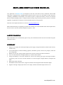
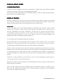
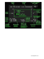
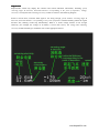
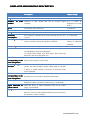
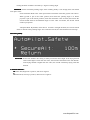
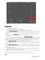
Skylark OSD V4.0 USER MANUAL
A skylark soars above the clouds.
www.SkylarkFPV.com
SKYLARK OSD V4.0 USER MANUAL
New generation of Skylark OSD is developed for the FPV (First Person View) enthusiasts. SKYLARK
OSD V4.0 is equipped with a multifunctional interface which is easy to use and stable. It offers extensive
scalability, affordability and reliability. The interface layout is simple and intuitive, and can be switched
between different display modes. Compact hardware design and powerful processors provide convenient
upgrades. Its appearance would give you the unlimited surprises and enjoyment.
Welcome to the Skylark FPV Service Center on www.SkylarkFPV.com.
SKYLARK OSD keeps on updating, the latest user manual can be downloaded online from Skylark FPV
Service Centre. This user manual is updated on April 11, 2012.
SATETY WARNING
SKYLARK OSD is for entertainment purpose only, users should bear all the risks involved when using this
electronics device.
SUMMARY
1. Simple to use, equip with video input/output, power supply voltage and transfer switches with one-way
interface only.
2. The functionalities provided including graphical, altitudinal, speed, return-arrow prompts, radar and
low-voltage alert.
3. Build-in 5V and 12V voltage outputs which can be used for camera and video transmission.
4. Users can switch between 3 display modes by a remote control channel.
5. Strong extensibility, six and four channels are reserved for steering gear input and output interfaces
respectively. There are also reserved interfaces for received signal strength detection, autopilot and
radio.
6. Built-in barometric altimeter.
7. Extendable triaxial infrared sensor, supports automatic return flight and multi destination flight.
8. Support 4-6S high-voltage input and 5V/12V output, with the maximum output current of 2A.
www.SkylarkFPV.com
MAIN CONNECTION
www.SkylarkFPV.com
INSTALLATION GUIDE
CONFIGURATION
A three-way switch is equipped, and each way corresponds to 1 display mode. If the channel for transfer
switch is not connected, details-mode would be displayed by default.
The current sensor and voltage detector are tuned before delivery, if there are relatively high deviations,
please contact us for the tuning software.
DISPLAY MODES
There are 3 display modes: details-mode, simple-mode and alarm-mode. These 3 modes can be switched
by a three-way switch on the remote control. Please refer to the “Operation Procedures” section for the
specific switching methods. Here are the introductions for these 3 display modes:
Details-mode
Details-mode displays most of the indication information, including latitude, longitude, numbers of GPS
satellites, speed, altitude, scrollbar, flying direction (shown by the plane icon), existing location &
direction corresponding to the point of departure, returning angle & direction, horizontal distance
corresponding to the point of departure, current, voltage, electricity consumption, remaining electricity,
flying time and signal indication of remote control, which are shown in the following diagram. The
rectangle in the center is the display range of the plane icon.
As a warning, many of the displayed information would flash.
When the GPS signal is not strong enough, latitude, longitude, numbers of GPS satellites, speed, altitude,
the plane icon, returning angle & direction, horizontal distance corresponding to the point of departure
would be flashing. When the signal becomes fine, flashing would stop automatically.
When user enters this mode the first time after charging, if positioning of the GPS has not yet been
completed, latitude and longitude would not be shown. The display area would appear the flashing words
of “GPS Searching Data”, which means the GPS is still searching for the satellites. To guarantee the
navigation information is accurate, please wait until the latitude and longitude data are displayed before
takeoff.
If the device is under interference, signal indication of remote control would flash for certain seconds, so
as to warn the user that it is out of the control range.
When there is a SD card, SD Card Indication would be displayed. If there is problem in data saving, this
display information would flash.
When it is under voltage because of not enough electricity (for example, the voltage of 3S battery is lower
than 10.6V), the voltage and remaining electricity would be flashing to remind user to take appropriate
actions, such as starting the return journey.
www.SkylarkFPV.com
www.SkylarkFPV.com
Simple-mode
Simple-mode would only display the common and critical indication information, including speed,
returning angle & direction, horizontal distance corresponding to the point of departure, voltage,
electricity consumption and remaining electricity, which are shown in the following diagram.
Same as Details-mode, when the GPS signal is not strong enough, speed, altitude, returning angle &
direction, horizontal distance corresponding to the point of departure would be flashing. When the signal
becomes fine, flashing would stop automatically. When it is under voltage because of not enough
electricity (for example, the voltage of 3S battery is lower than 10.6V), the voltage and remaining
electricity would be flashing to remind the user to take appropriate actions.
www.SkylarkFPV.com
Alarm-mode
The default Alarm-mode would not display any information, it would only display the corresponding
warning information and flash.
When the GPS signal is not strong enough, speed, altitude, returning angle & direction, horizontal
distance corresponding to the point of departure would be displayed and flash. When the signal becomes
fine, the information would disappear automatically. When it is under voltage because of not enough
electricity (for example, the voltage of 3S battery is lower than 10.6V), the voltage and remaining
electricity would be displayed and flash. The following diagram shows the Alarm-mode with under voltage
warning.
www.SkylarkFPV.com
DISPLAYED INFORMATION DESCRIPTION
Latitude
Longitude
Numbers of
satellites
Description
N is North Latitude, S is South Latitude, Unit is Degree
Display Range
90.0N~0~90.0S
E is East Longitude, W is West Longitude, Unit is Degree
180.0E~0~180.0W
GPS Numbers of GPS satellite that can be received signal 0~9; 9 would be
currently.
displayed even more
than 9
Total speed, unit is Km/ hour
0~999km/h
Speed
Current
Voltage
Electricity
consumption
Remaining electricity
Point of departure
Location & direction
Altitude
corresponding to the
point of departure
Returning angle &
direction
Operation current, unit is A
0.0~99.9A
System voltage, unit is V. it would flash when under voltage. 0.0~99.9V
The electricity consumed from system start-up till now, unit 0.0~9999mAH
is mAH
The battery symbol indicates the remaining electricity level, It takes a 2200mAH
when it is nearly used up, the symbol would flash.
battery as indication
standard.
Indicate the point of departure
The plane icon indicates the existing location & direction
corresponding to the point of departure.
Up: North, Down: South, Left: West, Right: East. The flying
direction is shown by the plane icon.
Altitude that corresponding to the point of departure. The -9999~9999m
figure can be negative, unit is meter.
Indicate the required angle and direction for a returning
journey, the unit for angle is degree. When angle is less than
5 degree, it would consider as accurate, so direction would
not be displayed.
Horizontal distance The horizontal distance corresponding to the point of 0~99.9km
corresponding to the departure, the unit would be adjusted automatically.
point of departure
SD Card indication
When there is a SD card, this information would be
displayed. If there is problem in data saving, it would flash.
Signal indication of When the device is under interference and out of control
remote control
range, it would flash.
Flying time
The flying time is accumulated from the first take-off. When
there are 4 or more GPS satellites and the speed exceeds 5m/s
the first time, it starts counting.
www.SkylarkFPV.com
AUTOPILOT SECTION
NSTALLATION FOR THE HARDWARE
1. Connection
a. Install the sensor GPSINS horizontally. The cable connector should be placed toward the nose.
b. According to the abovediagram,
PWM Input connect with RC receiver
Input 1 connect Aileron channel
Input 2 connect Elevator channel
Input 5 connect a 3-switch channel to switch autopilot mode
Input 6 connect a 3-switch channel to switch display mode
PWM output connect with servo
Output 1 connect Aileron servo
Output 2 connect Elevator servo
Input(3/4/7) and Output(3/4) are reserve channel
2. Keep the remote control in normal mode
In order to ensure the safe, please check all connections again before OSD power on.
3.
3.In
After OSD power on
4.After
on,, the following menu would be shown:
shown::
www.SkylarkFPV.com
System would detect the equipments that connected to the OSD control board automatically, then the
software & hardware version would be displayed.
Meanings of the information shown above:
HW
HW44.0 & SW
SW11.0
.0: represents hardware and software version are 4.0 and 1.0 respectively.
Logger
Logger: represents if the data logger is detected by the system. It flashes if the data logger is not
detected.
/INS
GPS
GPS/INS
/INS: represents if the GPS/INS is detected by the system. It flashes if GPS/INS is not detected.
RC CH IN
IN: is the RC receiver input channel
About 10 seconds after power connection, the system will enter one of the three modes. (It depends on
the switch status of the remote control.)
If the displayed information is different from the equipments connected, please check again before
take-off.
SOFTWARE SETTING
A After OSD initialization iscomplete
iscomplete,, the following menu would be shown:
www.SkylarkFPV.com
Select among the above items with the help of “Autopilot” channel switch, enter the corresponding
menu with the “Switch” channel switch.
Meaning of the menu:
Fly
ly: Enter the flying mode. If no action is taken, it would enter the flying mode automatically after a
while.
OSD
OSD: the OSD-related configuration page, including units, warnings, RSSI calibration etc. Enter the
OSD page when setting is needed.
Autopilot
utopilot: the Autopilot-related configuration page.
B.
B...Enter Autopilot menu.
Autopilot includes 5 sub-menu
Servos_Calibrate:Calibration input signal menu
Install_Relate:Installation setting menu
Control_PID:set the autopilot-related sensitivity
Control_MISC:miscellaneous setting, including the setting of maximum turning angle and safety
altitude etc.
Control_Safety:Safety parameters
Enter Install_Relate
menu to select airplane type;
C:
C:Enter
Install_Relatemenu
Tradition: is fixed wing, One port correspond one servo
Fly wing: is flying wing mode,1,2 channel will mix output.
Connect Aileron and Elevator servo
D:
D:Connect
Check the wing control output in manual mode
E. Servo_Calibrate Menu
Menu。
www.SkylarkFPV.com
The interface would display the real-time steering gear input values, with the range of -100 to +100.
After calibration, near 0 (< (+-5) is acceptable) would be shown when joystick is put in the center position.
Calibrate the “aileron
aileron”” channel
channel: Select the item of “Aile” with the help of “Autopilot” channel
switch, enter the menu with the “Switch” channel switch. At this moment, the figures after “Aile” would be
flashing, which means it is under calibration. First, keep the joystick in the center position for about 5
seconds. And then, put the aileron joystick to the end of the right-hand side for about 5 seconds. After that,
return to the center position and slide the “Switch” channel switch once. The figures would stop flashing,
which means calibration is completed. After calibration, near 0 would be shown when joystick is put in the
center position, near 100 would be shown when joystick is at the end of the right-hand side.
Calibrate the “Pitch
Pitch”” channel
channel: Select the item of “Elev” with the help of “Autopilot” channel switch,
enter the menu with the “Switch” channel switch. At this moment, the figures after “Elev” would be
flashing, which means it is under calibration. First, keep the joystick in the center position for about 5
seconds. And then, put the pitch joystick to the lowest position for about 5 seconds. After that, return to the
center position and slide the “Switch” channel switch once. The figures would stop flashing, which means
calibration is completed. After calibration, near 0 would be shown when joystick is put in the center
position, near 1000 would be shown when joystick is at the lowest position.
This calibration would calibrate the steering gear direction and travel as well, and it must be done
according to the above procedures.
And then, user needs to check if the direction is correct after calibration. For“aileron” channel, near 0
(< (+-5) is acceptable) would be shown when joystick is put in the center position, near 100 would be
shown when joystick is at the end of the right-hand side. For “Pitch” channel, near 0 (< (+-5) is acceptable)
would be shown when joystick is put in the center position, near 100 would be shown when joystick is at
the lowest position.
If the steering and displayed direction are inconsistent, then there would be an opposite control
direction. And the aircraft will turn over after entering the Balanced Mode
Mode.
There is no need to calibrate the “throttle” and “direction” channels at this moment.
Note: this operation must be done after the aircraft has completed the Manual Mode calibration. If the
steering gear has relatively large travel adjustment or mechanical calibration is undertaken, calibration
must be done once again.
Exit this menu.
F. Control_PID Menu
www.SkylarkFPV.com
Stability:Stabilization parameters
Roll_Aile:set the sensitivity for the aileron. If the aircraft vibrates in Balanced Mode
Mode, then user
should tune down the corresponding value. If user cannot get sufficient control for the aircraft, tune up the
value..
Pitch_Elev:set the elevator sensitivity, adjustment principle is same as above.
Yaw_Roll:set the sensitivity for the yaw. If the aircraft vibrates in Balanced Mode
Mode, then user should
tune down the corresponding value. If user cannot get sufficient control for the aircraft, tune up the value..
Alt_Pitch:set the height sensitivity, adjustment principle is same as above..
Control_MISC setting menu
G:C
MaxRoll
MaxRoll: Set the maximum rolling angle. If the turning angle is too small, then user should tune up
the value.
Semi-Automatic Mode: This value represents the maximum value that joystick can achieve.
When joystick is put in the center position, that means the turning angle is 0. When joystick
is put at the end of the right-hand side (reach the maximum value of 1000), that means
controlling the aircraft to the MaxRoll angle. For the value in between, the aircraft would
turn on proportion.
Autopilot Mode: This value represents the maximum turning angle. By default, 1 degree of
www.SkylarkFPV.com
turning deviation would be corrected by 1 degree of rolling angle.
MaxPitch
MaxPitch: Set the maximum pitching angle. If the climbing ability is not enough, then user should
tune up the value.
Semi-Automatic Mode: This value represents the maximum value that joystick can achieve.
When joystick is put in the center position, that means the pitching angle is 0. When
joystick is put at the lowest position (reach the maximum value of 1000), that means the
aircraft would climb in the MaxPitch angle. For the value in between, the aircraft would
climb on proportion.
Autopilot Mode: By default, when there is 10 meters of height deviation, the aircraft would
climb or descent in this pitching angle. Not to stall the aircraft, the value should not be too large.
H:Control_Safety
SecureAlt
SecureAlt: Set the safe Altitude. The setting is mainly used in the return flight. If the flying altitude
of the return flight is lower than this value, the aircraft would climb to the safe altitude.
If the flying altitude is higher than this value, the aircraft would keep flying with that
altitude.
Attitude indicator .
I:
I:Attitude
R:means Roll, Right roll is positive, left roll is negative
P:means Pitch, Nose-up is positive, otherwise it is negative
www.SkylarkFPV.com
FIELD TEST
A: Set the aircraft in Manual Mode
B: Adjust the travel and direction for the steering gear
C: Check the actual tilting angle is consistent with the displayed value in open area.
D: Enter Attitude Control Mode
Mode, check if the feedback direction is correct. If not, enter PWM menu
to confirm the joystick and display direction are consistent. If they are inconsistent, execute the calibration
again
E: Start flying under Manual Mode
Mode, observe the aircraft attitude is consistent with that shown in
infrared display.
F: When the aircraft flies above 50 meters, switch to the Attitude Control Mode and check the control
situation. [It is not suggested to use the infrared balancer under 50 meters because of the earth’s surface
interference.] If the aircraft vibrates, then user should tune down the corresponding value. Otherwise, user
can tune up the value and let OSD to have sufficient control in attitude balancing.
G: In Attitude Control Mode
Mode, put the Aileron joystick to the end of the right-hand side to check the
maximum rolling ability. If the rolling angle is too small, then user should tune up the MaxRoll value, and
vice versa.
H. In Attitude Control Mode
Mode, put the Elevator joystick to the maximum value and check the
maximum climbing & descending abilities. If the abilities are too weak, then user should tune up the
MaxPitch value, and vice versa.
I: Switch to Return Flight Mode from a short distance, observe the aircraft performances. Check if it
can control the flying attitude and hover for at least 5 laps.
J: If all above operations are under normal conditions, user can move on to the long distance return
flight.
K: If aircraft returns under normal conditions, user can set the waypoints and start flying.
Note
www.SkylarkFPV.com
The three-way switch of “Autopilot” represents:
is displayed on OSD, which is the Manual Mode
is displayed on OSD, which is the Attitude Control Mode
is displayed on OSD, which is the Return Flight Mode
is displayed on OSD, which is the Waypoints Mode
If there are 4 or more GPS satellites and the take-off position has not been locked, user will find the
flashing icon
in Return Flight Mode.
If the GPS is not connected or there are less than 4 satellites, user will find the flashing icon
.
That means it is not allowed to enter the Return Flight Mode.
All the parameters would be overwritten after software upgrade, thus calibration must be executed once
again.
In Flying Mode, user can quit the OSD Details-mode (by sliding the “Switch” channel switch 3 times) and
enter the Configuration Mode for adjustment. The Configuration Mode can be entered only within 30
meters from the take-off point.
www.SkylarkFPV.com