1
Installation and User manual of the AC10 - AC20 - AC30 controller
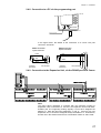
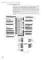
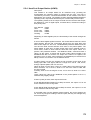
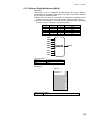
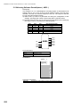
5.8.17 Analog To Digital converter ( A/D )
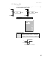
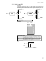
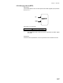
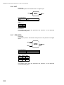
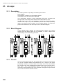
Description
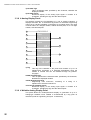
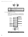
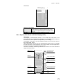
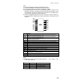
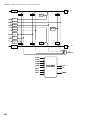
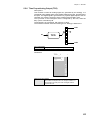
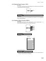
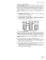
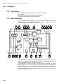
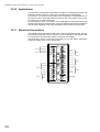
This module performs the conversion of a number, provided as an input
signal to the module, to a 16 bit binary number, specified through 16 digital
outputs. The range of the input number is 0 ÷ 65535. If the input number
exceeds this range, it is still converted in binary number, but the 16 digital
outputs corresponds to the status of the least significant bits. The Carry
output is not available, to flag the overrange: therefore, the strategy must
provide the actions to avoid or take care of this situation.
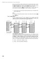
DO1
DO2
DO3
DO4
DO5
DO6
IN
A/D
DO7
DO8
DO9
DO10
DO11
DO12
DO13
DO14
DO15
DO16
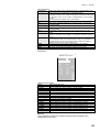
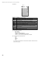
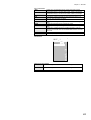
I/O Connections
IN
DO1 - DO16
Analog Input
Digital Output
Parameters
This module doesn’t have any parameter and, therefore, it is not displayed
on the instrument panel.
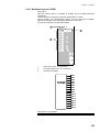
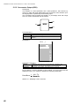
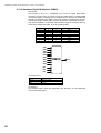
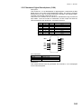
5.8.18 Digital To Analog Converter ( D/A )
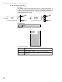
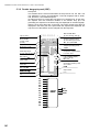
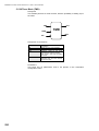
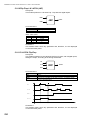
Description
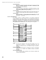
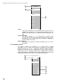
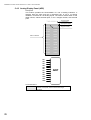
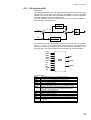
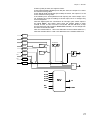
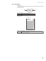
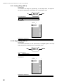
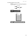
This module converts a 16 bit binary number, provided through 16 digital
inputs, into a number. The number is transferred out through the analog
output of the module, with range 0 to 65535. The Carry output is not
available.
DI1
DI2
DI3
DI4
DI5
DI6
DI7
DI8
DI9
D/A
OUT
DI10
DI11
DI12
DI13
DI14
DI15
DI16
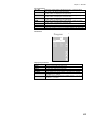
I/O Connections
OUT
DI1 - DI16
Analog Output
Digital Input
Parameters
This module doesn’t have any parameter and, therefore, it is not displayed
on the instrument panel.
124