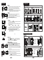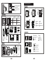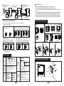
1
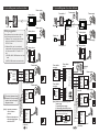
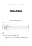
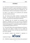
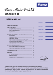
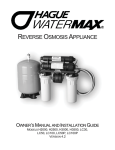
VILLA INTERCOM SYSTEM
Four-wire
Villa Intercom System
Installer & User Manual
Please read this user manual carefully
before using the products. Please keep
it for future reference.
Content
1. Components¡¡¡¡¡¡¡¡¡¡¡¡¡¡¡¡¡1
2. Door Station Installation¡¡¡¡¡¡¡¡¡¡¡1
,Any question towards our product
distributors or, please contact Genway agents
.Genway customer service center directly
3. Indoor Phone Installation ¡¡¡¡¡¡¡¡¡¡¡3
sale service consultation procedure-After
4. Door Station Switch Installation¡¡¡¡¡¡¡¡3
5. System Diagrams¡¡¡¡¡¡¡¡¡¡¡¡¡¡4
One door station¡¡¡¡¡¡¡¡¡¡¡¡¡¡4
◆Describe product name.
◆Describe product model.
◆Describe the trouble.
◆mail address-and e. Leave your Tel No.
Two door stations¡¡¡¡¡¡¡¡¡¡¡¡¡5
Signal unlock¡¡¡¡¡¡¡¡¡¡¡¡¡¡¡¡6
Power unlock¡¡¡¡¡¡¡¡¡¡¡¡¡¡¡¡6
Indoor phone Jumper Setting¡¡¡¡¡¡¡6
6. Specifications¡¡¡¡¡¡¡¡¡¡¡¡¡¡¡¡6
7. Product Appearance¡¡¡¡¡¡¡¡¡¡¡¡¡¡7
Statement
Please forgive us if we could not notify you timely
.towards any alteration to our product model No
.or technical parameter
s manual is not consistent with the actual'If the user
the, operations due to technology upgrading
.explanation right is reserved to Genway company
8. Operation¡¡¡¡¡¡¡¡¡¡¡¡¡¡¡¡¡¡8
VER:1.0
340302000860
1. Components
8. Operation
■ Call
Option of door station
1. When a visitor presses the call button of door station, the indoor
phone rings, and the screen shows the visitor's image.
2. If there is no answer, the system will automatically reset to
standby state after 60s.
F5D10
F5D50
F5S50
Accessories
F5S60
F5S70
Accessories
[Note] If the system have two door stations, it will ring busy tone when
calling from the other door station as the line is busy.
■ Talk
1. Pick up the handset of indoor phone to talk with the visitor.
(If hands-free indoor phone: press
button)
2. During talk, hang up the handset to end the talk.(If hands-free
indoor phone: press button)
Option of indoor phone
F3030
F3010
F3110
F3120
F3190
F3H40
[Note] It will automatically end the talk after 120s.
¡ Monitor
1. In standby state, press
button of indoor phone to monitor the
conditions around the door station.
2. If there are two door stations, the monitor for different entrances
is available by turns.
Press button
Press button
Press button
Press button
Door station 1
End monitor
Door station 2
Other fittings
¡ Door station switch ¡ Indoor phone accessories
¡ Power supply
¡ User manual
End monitor
3. In monitor state, pick up the handset of indoor phone can talk to
the visitor.(If hands-free indoor phone: press button)
[Note] It will automatically end the monitor after 60s;
If someone calls from door station, it will end monitoring and
begin to call immediately.
Indoor phone with built-in
power supply doesn't use
this.
This device is used in "two
door stations" system.
[Note] The power supply varies in different countries, please check with us before ordering.
2. Door Station Installation
Unit: mm
F5S50
Unlock
45.5
128
■
Mute setting
¡ Intercom
between
indoor phone
Adjust
the state,
[Ring
Volumebutton
Adjustment]
phone
to the
1.In
standby
press
in any of
of indoor
the indoor
phones
lowest,
the ring will turn off, and the indicator is on.
st
(1 indoor phone), the other indoor phones will ring together.
2.Pick up the handset (if hands-free indoor phone: press button)
¢
60.5
¢
In ring, talk or monitor state, press
button of indoor phone to
open the door, at the same time, the door phone and the indoor
phone will sound "di" to prompt that door is open.
92
■
Unit: mm
will stop ringing;
press
button) of the 1st indoor phone, intercom is available
between the 1st and the 2nd indoor phones.
[Note] 1.You can also pick up the handset of the indoor phone, then
press
button to start the intercom.
2.There is no image during the intercom between indoor phone.
8
¢
¢
94
of one indoor phone (2nd indoor phone), the other indoor phones
3.At this time pick up the handset (if hands-free indoor phone:
¢
¢ Door/Wall
¢ Panel
¢ Frame
¢ Screw
¢
¢ Door/Wall
¢ Panel
¢ Frame
¢ Screw
1
Change name plate
7. Product Appearance
1.Insert the screw driver in the
notch. Turn and push the
Name plate plastic upwards.
2.Change the name plate.
3.Put the plastic back to the
Plastic
groove.
Door station
F5D10/F5D50
Built-in Installation
D1
Iron door
Wall
Installation size Installation size
D2
H1
H2
(H1)¡(W1)¡(D1)
W1
F5D10 166¡108¡38
164¡126¡42
F5D50 208¡108¡38
206¡126¡42
W2
Camera
MIC
Speaker
Call button
Name plate
Sensitive LED
Unit: mm
Change name plate
¢
¢
201
¢
¢
(H2)¡(W2)¡(D2)
Name plate
¢
¢
Plastic
2.Take off 3.Change the name
plate
the plastic.
1.Push the right edge
and move to right.
Indoor phone
¡ Status indicator
¢
¡ Buttons
Busy indicator
Talk button
Monitor button
Mute indicator
Unlock button
Power Supply indicator
¢ Door/Wall ¢ Panel
¢ Frame
¢ Screw
¢ Plugs
4.Then insert the right
edge into sideling.
F5S70
Unit: mm
¢
58
48
¢
60
135
¢
¢
¢
¢
Internal call button
5.Push the left edge
and move to left.
¡ Adjustment
Brightness Adjustment
¡ During installation, put
the wire through the hole
of PC plate, then connect
it with door station terminal,
and glue the PC plate on
the door station rear panel
at last.
Contrast Adjustment
Chroma Adjustment
Ring Volume Adjustment
Talk Volume Adjustment
¢ Door/Wall ¢ Panel ¢ Frame
¢ Screw
¢ PC plate
2
7
Signal unlock (Note: this way of unlocking needs separate power supply.)
COM
NC
NO
Magnetic
lock
(Note: only F5D10, F5D50, and F5S50
have this function)
NO connection
NC connection
Power
supply
COM
NC
NO
Electric lock
Power unlock
Short circuit
Power
supply Door station Electric lock
Door station
terminal
terminal
+12V
COM
NC
NO
GND
Door station
terminal
Installation tips
¡ Don't install door station near humid ,stove, and dusty condition.
¡ Mind the installation size while producing a groove for the back cover.
¡ Control the depth of the groove carefully so that it is the same as the one of the back
cover.
¡ There are waterproof silicon sheet attached on the door station's back side, please
install the door station to the smooth wall to guarantee the waterproof function.
¡ We suggest the installation height between 1100mm and 1400mm.But please also
consider other situations such as view angle of the camera and disabled persons.
Indoor phone Jumper Setting
3. Indoor Phone Installation
There are several jumpers on indoor phone rear panel, adjust them as follows:
1. Main indoor phone setting
Bracket
If have one indoor phone, adjust the
jumper as follows:
Unit: mm
Size:
If have more then one indoor phone, set one of indoor
phone as the main indoor phone, and set the others as
subsidiary indoor phone, adjust the jumper as follows:
185X120X31
66mm
Main indoor phone
2. Unlock time setting
The unlock time on the indoor phone can be
set separately. Adjust the jumper as follows:
Unlock time: 1s
Subsidiary indoor phone
3. Video matching
The last indoor phone's Video matching jumper should
be "ON". The "System Diagrams" has the details.
Video matching: ON Video matching: OFF
Unlock time: 5s
60mm
110X86X20
Method 1
Method 1
Method 2
[Note] Please disconnect the power when setting the jumpers, after completing, restart
the indoor phone.
6. Specifications
Camera
color camera
(or it is B&W)
Function:
Call/Talk/Access control
Shell No.
Villa door station code
Four-wire system
Indoor
phone
model
Operating voltage: DC 14V
Operating current: 200mA(DC 14V)
Quiescent current: 30mA(DC 14V)
Temperature: -40¡~+70¡
Humidity: 10£~95£
Color
Black & White
1/3 CCD&CMOS
1/3 CCD&CMOS
PAL system
PAL system
Visible angle: 90¡
Visible angle: 90¡
Light source:
Light source: infrared
white light LED
Min. Illumination:
Min. Illumination:
0.1 Lux
0.1 Lux
Technical
parameter
6
B: Black & White
(or it is color)
N: Built-in power supply
Number: Lcd screen size
Function:
Call/Talk/Access control
Shell No.
Indoor phone code
Four-wire system
Operating voltage: DC 14V
Operating current: 700mA(DC 14V)
Quiescent current: 100mA(DC 14V)
Temperature: -10¡~+55¡
Humidity: 10£~95£
Screen size: 4¡CRT/ 5¡TFT/ 7¡TFT
Resolution: ¡450 Line/320*324/480*324
4. Door Station Switch Installation
69mm
Technical
parameter
F3010 /F3030 / F3110 / F3120
/ F3190/ F3H40
F 3 03 0 - X
F 5 D1 0 - C
80mm
Door
station
model
F5D10
F5D50
F5S50
F5S60
F5S70
66mm
91mm
3
Method 2
5. System Diagrams (one door station)
5. System Diagrams (two door stations)
Power supply
Power supply
4
2
Magnetic lock
Door station
Wiring suggestion:
4
4
Electric lock
Power supply
4
Door station 2
hand in hand, as the right
diagrams shows.
[Note] 1. system can connect
with 1~4 indoor
phones.
2.The last indoor phone's
video matching jumper
should be "ON".
VDOOR
AUDIO
GND
VIDEO
VDOOR
AUDIO GND
DC14V
GND
VIDEO
Video matching
Indoor phone terminal
VDOOR
AUDIO
GND
VIDEO
Indoor phone terminal
(Last one)
4
3
2
1
+
4
Power supply
-
VDOOR
AUDIO GND
GND
DC14V
VIDEO
3
2
1
Door station 2
Door station
terminal
(optional)
DC14V
4
3
2
1
VDOOR
AUDIO
GND
VIDEO
Indoor phone terminal
Power supply
Power supply
Door station
switch
Door station
terminal
VDOOR
AUDIO GND
DC14V
GND
VIDEO
4
Indoor phone
Indoor phone
Video matching
wiring between indoor
! The
phones must be connected
Indoor phone
2
Power supply
Door station terminal
4
Indoor phone
Wiring distance from door station to the last
indoor phone should be less than 100m.
1. If distance¡ 50m, use quad cable, with the
single wire resistance £4¦. Recommend
RVV4¡0.75 wire.
2. If distance£50m, use 3-core cable and
coaxial-cable, with the single wire resistance 4
£4¦. Recommend RVV3¡1.0 and SYV-75
wire.
1) VDOOR, AUDIO, GND terminal use 3-core
cable.
2) VIDEO, GND terminal use coaxial cable.
VDOOR
COM
AUDIO
NC
GND
NO
VIDEO
Door station
switch
Power supply
4
Indoor phone
Lock
4
Indoor phone
2
Door station 1
2
Power supply
Door station 1
Indoor phone
Indoor phone
terminal
Video matching
-
Video matching
Indoor phone terminal
use the power supply from the indoor
phone, the wiring as follows:
+
Power supply
VDOOR
AUDIO GND
DC14V
GND
VIDEO
[Note] Switch have two method to get the
power supply.
1. Separately power supply.
2. Power supply from indoor phone.
DC14V
Video matching
VDOOR
AUDIO
GND
VIDEO
DC14V
GND
Door station switch Indoor phone
terminal
terminal
5
Indoor phone terminal
(Last one)
Video matching