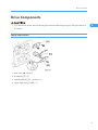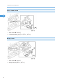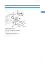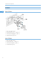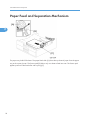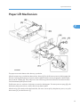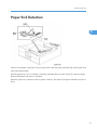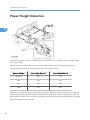
1
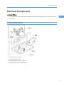
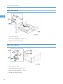
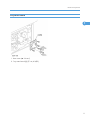
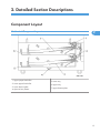
PAPER TRAY UNIT (Machine Code: D331) SERVICE MANUAL March, 2007 Subject to change Safety and Symbols Replacement Procedure Safety • Turn off the main power switch and unplug the machine before beginning any of the replacement procedures in this manual. Symbols Used in this Manual This manual uses the following symbols. *: See or Refer to : Screws : Connector : Clip ring : E-ring 1 TABLE OF CONTENTS Safety and Symbols............................................................................................................................................1 Replacement Procedure Safety.....................................................................................................................1 Symbols Used in this Manual........................................................................................................................1 1. Replacement and Adjustment Covers and Roller...............................................................................................................................................3 Covers.............................................................................................................................................................3 Feed Roller......................................................................................................................................................4 Drive Components..............................................................................................................................................5 Upper Feed Clutch.........................................................................................................................................5 Lower Feed Clutch..........................................................................................................................................6 Relay Clutch....................................................................................................................................................6 Paper Feed Motor..........................................................................................................................................7 Lift Motors........................................................................................................................................................8 Electrical Components........................................................................................................................................9 Vertical Transport Sensor...............................................................................................................................9 Paper End Sensor.........................................................................................................................................10 Paper Size Sensors......................................................................................................................................10 Tray Main Board..........................................................................................................................................11 2. Detailed Section Descriptions Component Layout...........................................................................................................................................13 Mechanical Component Layout.................................................................................................................13 Electrical Component Layout......................................................................................................................14 Electrical Component Description..............................................................................................................15 Drive Layout..................................................................................................................................................17 Paper Feed and Separation Mechanism.......................................................................................................18 Paper Lift Mechanism.......................................................................................................................................19 Paper End Detection........................................................................................................................................21 Paper Height Detection....................................................................................................................................22 Paper Size Detection........................................................................................................................................23 Side and End Fences........................................................................................................................................25 Side Fences..................................................................................................................................................25 End Fence.....................................................................................................................................................25 2 1. Replacement and Adjustment Covers and Roller 1 • Turn off the main power switch and unplug the machine before beginning any of the procedures in this section. Covers Rear Cover 1. Hold brackets [A] ( x 1 each) 2. Rear cover [B] ( x 3) Right Cover 1. Right side stopper [C] ( x 3) 2. Right cover [D] ( x , knob screw x 2) 3 1. Replacement and Adjustment Feed Roller 1 1. Pull out the tray [A]. 2. Release the lock lever [B]. 3. Feed roller [C] 4 Drive Components Drive Components • Turn off the main power switch and unplug the machine before beginning any of the procedures in this section. 1 Upper Feed Clutch 1. Rear cover (* "Covers") 2. Bracket [A] ( x 2) 3. Hold bracket [B] ( x 1, bushing x 1) 4. Upper feed clutch [C] ( x 1) 5 1. Replacement and Adjustment Lower Feed Clutch 1 1. Rear cover (* "Covers") 2. Lower feed clutch [A] ( x 1, x 1, x 1) Relay Clutch 1. Rear cover (* "Covers") 2. Relay clutch [A] ( x 1, x 1) 6 Drive Components Paper Feed Motor 1 1. Rear cover (* "Covers") 2. Tray main board (* "Tray Main Board") 3. Gear [A] ( x 1) 4. Paper feed motor bracket [B] ( x 5) 5. Paper feed motor [C] ( x 2) 7 1. Replacement and Adjustment Lift Motors 1 Upper Lift Motor 1. Rear cover (* "Covers") 2. Spring [A] (snap ring x 1, spacer x 1) 3. Lift motor bracket [B] ( x 3, x 1) 4. Upper lift motor [C] ( x 3) Lower Lift Motor 1. Rear cover (* "Covers") 2. Spring (snap ring x 1, spacer x 1) 3. Lift motor bracket ( x 4, x 1) 4. Lower lift motor ( x 3) 8 Electrical Components Electrical Components • Turn off the main power switch and unplug the machine before beginning any of the procedures in this section. 1 Vertical Transport Sensor 1. Open the tray cover [A] 2. Guide plate [B] ( x 2) 3. Sensor bracket [C] ( x 1, x 1) 4. Vertical transport sensor [D] (hooks) 9 1. Replacement and Adjustment Paper End Sensor 1 1. Pull out the tray [A] 2. Sensor bracket [B] ( x 1, x 1) 3. Paper end sensor [C] (hooks) Paper Size Sensors 1. Pull out the two trays. 2. Sensor bracket cover [A] ( x 1) 3. Sensor bracket [B] ( x 3, x 2) 4. Paper size sensors (hooks) 10 Electrical Components Tray Main Board 1 1. Rear cover (* "Covers") 2. Tray main board [A] ( x 4, all 's) 11 1. Replacement and Adjustment 1 12 2. Detailed Section Descriptions Component Layout 2 Mechanical Component Layout 1. Upper paper feed roller 2. Lower paper feed roller 3. Lower bottom plate 4. Optional tray heater 5. Lower tray 6. Upper tray 7. Upper bottom plate 13 2. Detailed Section Descriptions Electrical Component Layout 2 14 1. Paper feed motor 12. Lower paper height 1 sensor 2. Upper lift sensor 13. Vertical transport sensor 3. Upper lift motor 14. Lower tray set switch 4. Upper tray set switch 15. Lower paper end sensor 5. Upper paper height 2 sensor 16. Upper paper end sensor 6. Upper paper height 1 sensor 17. Optional tray heater 7. Upper paper feed clutch 18. Lower lift motor 8. Relay clutch 19. Lower paper size sensors 9. Tray cover switch 20. Lower lift sensor 10. Lower paper feed clutch 21. Upper paper size sensors 11. Lower paper height 2 sensor 22. Tray main board Component Layout Electrical Component Description Symbol Name Function Index No. Motors M1 Paper Feed Drives all rollers. 1 M2 Upper Lift Lifts the upper tray bottom plate. 3 M3 Lower Lift Lifts the lower tray bottom plate. 18 S1 Upper Lift Detects when the paper in the upper tray is at the correct feed height. 2 S2 Lower Lift Detects when the paper in the lower tray is at the correct feed height. 20 S3 Upper Paper End Informs the copier/printer when the upper tray runs out of paper. 16 S4 Lower Paper End Informs the copier/printer when the lower tray runs out of paper. 15 S5 Vertical Transport Detects misfeeds. 13 S6 Upper Paper Height Detects the amount of paper in the upper tray. 1 6 S7 Upper Paper Height Detects the amount of paper in the upper tray. 2 5 S8 Lower Paper Height Detects the amount of paper in the lower tray. 1 12 S9 Lower Paper Height Detects the amount of paper in the lower tray. 2 11 S10 Upper Paper Size Determines what paper size is in the upper tray. 21 S11 Lower Paper Size Determines what paper size is in the lower tray. 19 Tray Cover Detects whether the tray cover is opened or not. 9 2 Sensors Switches SW1 15 2. Detailed Section Descriptions SW2 Upper Tray Set Detects whether the upper tray is opened or not. 4 SW3 Lower Tray Set Detects whether the lower tray is opened or not. 14 Magnetic Clutches 2 MC1 Upper Paper Feed Starts paper feed from the upper tray. 7 MC2 Lower Paper Feed Starts paper feed from the lower tray. 10 MC3 Relay Drives the relay rollers. 8 Tray Main Controls the paper tray unit and communicates with the copier/printer. 22 Optional Tray Heater Removes humidity from the paper in the trays. 17 PCBs PCB1 Others H1 16 Component Layout Drive Layout 2 1. Paper feed motor 5. Lower paper feed clutch 2. Drive belt 6. Upper paper feed roller 3. Upper paper feed clutch 7. Relay roller 4. Relay clutch 8. Lower paper feed roller 17 2. Detailed Section Descriptions Paper Feed and Separation Mechanism 2 The paper tray holds 500 sheets. The paper feed roller [A] drives the top sheet of paper from the paper tray to the copier/printer. The friction pad [B] allows only one sheet to feed at a time. The friction pad applies pressure to the feed roller with a spring [C]. 18 Paper Lift Mechanism Paper Lift Mechanism 2 The paper size switch detects when the tray is pushed in. When the paper tray is pushed into the machine, the pin [A] for the lift motor pressure shaft engages the lift motor coupling [B] and the pin [C] for the bottom plate lift shaft in the tray engages the bottom plate pressure lever coupling [D]. The pin [E] on the rear of the tray pushes the lock lever so that the lift motor can lift the bottom plate pressure lever. The lift motor turns on, and turns clockwise as viewed on the diagram. The main pressure spring [H] pulls the bottom plate pressure lever, and this lifts the tray bottom plate. When the top of the stack touches the feed roller, the motor cannot pull up the plate any more, so it pulls the actuator [G] into the lift sensor [F]. 19 2. Detailed Section Descriptions The pressure of the feed roller on the paper is now too high, so the lift motor reverses to reduce this pressure. It reverses for 300 ms or 600 ms, depending on the paper size. For smaller paper, it reverses the larger amount (600 ms) to reduce the pressure more. 2 20 When the paper tray is pulled out, the pins [A, C] disengage from the couplings [B, D], and the bottom plate drops. To make it easier to push the tray in, the lift motor rotates backwards 1.7 seconds to return the bottom plate pressure lever coupling [D] to the original position. Paper End Detection Paper End Detection 2 If there is some paper in the paper tray, the paper stack raises the paper end feeler [A] and the paper end sensor [B] is deactivated. When the paper tray runs out of paper, the paper end feeler drops into the cutout [C] in the tray bottom plate and the paper end sensor is activated. When the paper tray is drawn out with no paper in the tray, the shape of the paper end feeler causes it to lift up. 21 2. Detailed Section Descriptions Paper Height Detection 2 The amount of paper in the tray is detected by the combination of on/off signals from two paper height sensors [A] and [B]. When the amount of paper decreases, the bottom plate pressure lever [C] moves the actuator up. The following combination of sensor signals is sent to the copier/printer. Amount of Paper Paper Height Sensor 1 Paper Height Sensor 2 Near End OFF ON 30% ON ON 70% ON OFF 100% OFF OFF When the tray contains paper of a small width, the paper feed pressure may become too low when the thickness of the remaining stack of paper has decreased. The lift motor rotates forward 300 ms after the sensor detects a certain amount of paper remaining in the tray to increase paper feed pressure, simulating the pressure generated by a full tray. 22 Paper Size Detection Paper Size Detection 2 There are three paper size sensors [A] (SN1, SN2 and SN3) on the paper tray unit. Each paper tray has its own actuator [B], with a unique combination of notches. This actuator is moved when the paper end fence [C] is adjusted for the installed paper. To determine which size has been installed, the CPU reads which paper size sensors the actuator has switched off. Refer to the size detection lists as shown below. EU/ AISA Size SN1 SN2 SN3 SP Setting A6 SEF 148 x 105 OFF ON OFF A5 LEF B5 LEF 182 x 257 ON OFF ON B6 SEF/ Exe LEF A4 LEF 210 x 297 ON ON OFF LT LEF/ A5 SEF/ HLT SEF B5 SEF 257 x 182 OFF OFF ON LT SEF 279 x 216 OFF OFF OFF A4 SEF 297 x 210 ON OFF OFF B4 SEF 364 x 257 ON ON ON A3 SEF 420 x 297 OFF ON ON SN1 SN2 SN3 NA Size LG SEF DLT SEF SP Setting 23 2. Detailed Section Descriptions 2 A6 SEF 148 x 105 OFF ON OFF A5 LEF B5 LEF 182 x 257 ON OFF ON Exe LEF/ B6 SEF LT LEF 210 x 297 ON ON OFF A4 LEF/ A5 SEF/ HLT SEF B5 SEF 257 x 182 OFF OFF ON LT SEF 279 x 216 OFF OFF OFF A4 SEF 297 x 210 ON OFF OFF LG SEF 364 x 257 ON ON ON DLT SEF 420 x 297 OFF ON ON A3 SEF The CPU disables paper feed from a tray if the paper size cannot be detected. If the paper size actuator is broken, or if there is no tray installed, the Add Paper indicator will light. 24 Side and End Fences Side and End Fences 2 Side Fences If the tray is full of paper and it is pushed in strongly, the fences may deform or bend. This may cause the paper to skew or the side-to-side registration to be incorrect. To correct this, each side fence has a stopper [A] attached to it. Each side fence can be secured with a screw [B], for customers who do not want to change the paper size. End Fence As the amount of paper in the tray decreases, the bottom plate [C] lifts up gradually. The end fence [D] is connected to the bottom plate. When the tray bottom plate rises, the end fence moves forward and pushes the back of the paper stack to keep it squared up. 25 MEMO 26 MEMO 27 MEMO 28