1
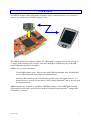
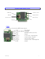
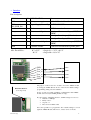
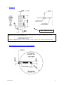
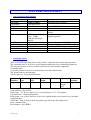
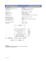
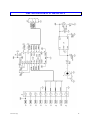
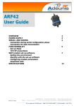
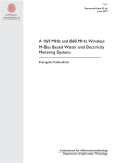
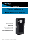
ARF32 SYSTEM USER GUIDE
CONFORM ITY
2
OVERVIEW
3
H ARDW ARE ESSENTIALS
4
Pinout
4
Interface
5
Footprint
6
Recommended exclusion zone around antenna 6
SOFTW ARE M ANAGEM ENT
7
Non Volatile Default Settings
7
Operating modes
7
Setting up a link using the command interface 8
Advanced commands
8
SPECIFICATIONS
9
ARF7069 DEM OKIT SCH EM ATICS
10
05-04-V4-pcy
1
DECLARATION OF CONFORMITY
according to ISO/IEC Guide 22 and EN45014
Manufacturer’s name:
ADEUNIS R.F.
Manufacturer’s address
Parc technologique PRE ROUX IV
283 rue Paul Louis NEEL
38920 CROLLES - FRANCE
declares that the product
Product Name:
Product Number(s):
Product options:
ARF32
ARF7044A
conforms to the RTTE Directive 99/5/EC :
EMC
: conformity is proven by compliance to the standard EN 301-489
according to the requirements of EMC Directive 89/336/EEC.
Safety
: conformity to the standard EN 60-950 according to the requirements of Low
Voltage Directive 73/23/EEC.
Radio
: conformity is proven by compliance to harmonised standard
EN 300-328 covering essential radio requirements of the RTTE
directive.
.
Notes
:- Conformity has been evaluated according to the procedure
described in Annex III of the RTTE directive.
- The use of the spectrum is harmonised by the fact that the product
never falls in one of the restrictions listed in appendix 3 (Annex 1,
band E) of the CEPT recommendation 70-03.
- Receiver class (if applicable) : 2.
Crolles, April 4th, 2005
VINCENT Hervé / Quality manager
05-04-V4-pcy
2
OVERVIEW
The ARF32 module enables Bluetooth® compliant duplex communications over a 20 meters
range in the world-wide 2.45 GHz frequency band.
The ARF32 module full complies with the V1.1 Bluetooth® standard and data rate goes up to
723 kbps. Data exchange and set-up are only done through an UART data port, under SPP
profile. Miniature antenna is integrated.
ARF32 can be used in two modes :
Classical Bluetooth® mode : Master starts with GAP identification, then, SDAP profile
review, SPP connection and transparent communication.
Automatic Bluetooth® mode : Identification, profile review and connection to 1 to 3
known slaves are recorded by the master. After booting, Bluetooth® link is directly open
in transparent mode.
ARF32 modules are available as standalone ARF7044 module or in the ARF7069 demo kit.
This demo kit can be fully set-up and used with the National Semiconductors® “Simply Blue
Commander” Software.
05-04-V4-pcy
3
HARDWARE ESSENTIALS
32 kHz Xtal
« Data rate » resistor
Main Xtal
Integrated antenna
Bluetooth® Chip
Bottom Connector
•
Pinout
All connections are located on the ARF32 bottom connector :
VCC
= Power Supply
VDD_DIG_PWR_D# = UNUSED
05-04-V4-pcy
Reset
= Full Hardware Reset (active low)
GND
= Ground
Uart_cts
= « Clear to send » Control Signal In
Uart_tx
= « Data to transmit » Data Out
Uart_rx
= « Received data » Data In
Uart_rts
= « Request to send » Control Signal Out
GND
= Ground
4
•
Interface
Pin description
SIGNAL
I/O DESIGNATION
Comment
VCC
I
Main power supply
2.85 < VCC < 3.6 V and I < 65 mA
VDDDIG_PWR_D#
Reset
I
Digital Supply Power Up NOT TO BE USED
I
Hardware reset
ARF32 reset when Low
Uart_cts
I
Clear to send Signal
Uart_tx
O
Data to transmit
Serial port Flow control Input (MUST BE
USED)
Serial port Data Output (0/Vcc level)
Uart_rx
I
Received data
Serial port Data Input (0/Vcc level)
Uart_rts
O
Request to send Signal
GND
-
Common Ground
Serial port Flow control Output (MUST BE
USED)
Connected to motherboard ground plane
NB : For all I/Os :
0.7 x VCC
- 0.5 V
< Logical 1 < VCC + 0.5 V
< Logical 0 < 0.3 x VC
Associated UART
Use of the Data Rate Resistor
Data Rate Resistor
(red component)
GND
Uart_cts
Uart_tx
Uart_rx
Uart_rts
GND
RTS
RXD
TXD
CTS
The purpose of this resistor is to be able to access the ARF32 module
by forcing the UART data rate in case of bad “Non Volatile Settings”
programming during test and evaluation.
In case of setup error while evaluating, communication with ARF32
module can be lost (bad UART parameters setup).
By removing the “Data Rate Resistor”, UART settings are forced to :
• Data rate = 9600 bps
• Parity = None
• Stop bit = 1
• Flow Control = RTS / CTS
It becomes possible to re-program the “Non volatile Settings” to access
again the ARF32 Module. When done, resistor can be re-mount.
05-04-V4-pcy
5
•
Footprint
TOP or BOTTOM VIEW
NB : When delivered with ARF7069 demokits, ARF7044 sample modules use a 2 mm pitch connector.
Usable references for mass production are :
- SAMTEC TMM-109-01-LL-S-RA
- RADIOSPARE 132-1083
Standalone ARF7044 module doesn’t include this connector because of the suggested plugged mounting.
•
Recommended exclusion zone around antenna
05-04-V4-pcy
6
SOFTWARE MANAGEMENT
•
Non Volatile Default Settings
Parameter
BDADDR
Local Name
PIN Code
Mode
Default connections
Default Value
HARD CODED
Serial port device
0000
Automatic
0
SDP database
1 SPP entry :
Name : COM1
Authentif & Encrypt
enabled
9600
1 Stop bit, parity none
0000 0001
No link keys
2
UART speed
UART settings
Ports to open
Link keys
Security mode
•
Description
Bluetooth Device Address
Bluetooth PIN Code
Command or Automatic mode
Up to three default devices to connect on
default
Service discovery database, control for
supported profiles
Speed of the physical UART interface
Settings of the physical UART interface
Defines the RF Comm port to open
Link keys for paired devices
Security mode
Operating modes
There is two main operating modes in the module : command mode and transparent mode.
The command mode is used to set up the bluetooth link between two bluetooth equipments.
The transparent mode is used to transfer data between two bluetooth equipments.
Command mode
A specific protocol is used to send commands to the bluetooth module.
The frame format is the following :
All the values are in hexadecimal format.
Start
delimiter
1 byte
Packet
type
1 byte
Operation
code
1 byte
Data
length
2 bytes
Checksum Data
1 byte
<data
length>
bytes
End
delimiter
1 byte
Start delimiter : 02 (<STX>)
Packet type : 52 (‘R’ for request), 69 (‘i’ for indication), 43 (‘C’ for confirm)
Operation code : command dependent
Data length : size of data. First byte is the Least Significant Byte and second byte is the Most
Significant Byte
Checksum : Sum of all bytes from the packet type field to the data length field
Data : command data
End delimiter : 03 (<ETX>)
05-04-V4-pcy
7
Example the inquiry command
Start
Packet
Operation Data
delimiter
type
code
length
02
52
00
03 00
Frame : 02 52 00 03 00 55 0A 00 00 03
Checksum Data
55
0A 00 00
End
delimiter
03
transparent mode
In this mode all the data received on the UART RX pin are sent by radio to the target bluetooth
module and will be available on the target bluetooth module UART TX pin.
mode selection
A specific command (tranparent mode) is used in order to switch from command mode to
transparent mode.
A specific pattern : “UART break” is used to switch from transparent mode to command mode.
•
Setting up a link using the command interface
Power up the two bluetooth modules. Connect one module with the RS232 link to a PC or
Notebook or PDA. Use a terminal software configured at the current baudrate (9600 by
default), 8 bits, 1 stop, no parity, flow control material.
Please find below a typical request / response sequence in order to establish a typical link. All
request must be send by the PC / NB / PDA (i.e. the master). All indication and confirm
responses are sent by the Bluetooth slave module :
> GIAC Inquiry request :
02 52 00 03 00 55 0A 00 00 03
< Inquiry module indication :
02 69 01 09 00 73 34 BE 1F 17 00 08 00 00 00 03
In bold : address of the target bluetooth module. This address will be used within the command
SDAP Connect and the command SPP Connect
< Inquiry module confirm :
02 43 00 01 00 44 00 03
> SDAP connect request :
02 52 32 06 00 8A 34 BE 1F 17 00 08 03
< SDAP connect module confirm :
02 43 32 01 00 76 00 03
> SDAP service browse SPP request :
02 52 35 02 00 89 01 11 03
< SDAP service browse SPP module confirm : 02 43 35 0D 00 85 00 01 02 10 01 11 01 05 43 4F
4D 31 00 03
> SDAP disconnect request :
02 52 33 00 00 85 03
< SDAP disconnect module confirm : 02 43 33 01 00 77 00 03
> SPP connect request :
02 52 0A 08 00 64 01 34 BE 1F 17 00 08 01 03
< SPP connect module confirm :
02 43 0A 02 00 4F 00 01 03
< SPP connect module indication :
02 69 3E 04 00 AB 01 0C 00 00 03
> Enter transparent mode :
02 52 11 01 00 64 01 03
< Enter transparent mode module confirm : 02 43 11 02 00 56 00 01 03
Now you can exchange data in transparent mode between the two bluetooth modules.
To come back to the command mode you have to send an UART break.
•
Advanced commands
Other commands are available in command mode. Please refer to the National Semiconductors
“Simply Blue Commander Software and “Software User Guide”
05-04-V4-pcy
8
SPECIFICATIONS
Rough data rate
UART programmable data rates
UART ports
723 Kbps
Standards from 9.6 to 921.6 kbps
TXD - RXD - RTS - CTS
Frequency
Radiated RF power
Sensivity
Operating range
FHSS / 2.402 to 2.480 GHz
2 mW (3 dBm)
-85 dBm for BER 10-3
>20 m when plugged (with exclusion zone)
Operating voltage
TX / RX consumption
PowerDown current
Power supply rise time
3.3V nominal (2.85 to 3.6 V)
40 mA
250µA (When software powered down)
50 ms
Operating temperature
Dimensions
-35°C / +80°C
20 x 24 x 4 mm
References
ARF7044A : Plugged Bluetooth® Class 2 Complete Module
ARF7069B : RS232 Demo Kit
05-04-V4-pcy
9
ARF7069 DEMOKIT SCHEMATICS
05-04-V4-pcy
10