1
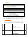
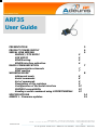
ARF35
User Guide
PRESENTATION
PRODUCT POWER SUPPLY
SERIAL LINK WIRING
MODEM / DTE RS232
DCE RS232
RS485 wiring
RS485 interface activation
5
5
5
6
Communication channels
RSSI reading
7
7
Addressed mode
Serial commands
Set of commands
Description of the registers
Configuration of the serial interface
MODBUS compatibility
Sending a serial command using HYPERTERMINAL
8
8
9
9
12
13
13
RADIO COMMUNICATION
WORKING MODE
SPECIFICATIONS
ANNEX 1 - Firmware updates
06-06-V6-smn
3
4
5
7
8
14
15
ADEUNIS RF – 283 RUE LOUIS NEEL – 38920 CROLLES FRANCE
DESK : +33 (0) 4 76 92 07 77 – FAX +33 (0) 4 76 08 97 46 E.MAIL : [email protected]
________________________________________________________________________________________
p1
SA au capital de 345.000 euros – SIRET 430 190 496 00017 – RCS Grenoble – NAF 322A
DECLARATION OF CONFORMITY
according to ISO/IEC Guide 22 and EN45014
Manufacturer’s name: ADEUNIS R.F.
Manufacturer’s addressParc technologique PRE ROUX IV
283 rue Paul Louis NEEL
38920 CROLLES - FRANCE
declares that the product
Product Name:
Product Number(s):
Product options:
ARF35
ARF7120C / ARF7120D / ARF7120E / ARF7120F
conforms to the RTTE Directive 99/5/EC:
EMC: conformity is proven by compliance to the standard EN 301489 according to the
requirements of EMC Directive 89/336/EEC.
Safety: conformity to the standard EN 60950 according to the requirements of Low Voltage
Directive 73/23/EEC.
Radio: conformity is proven by compliance to harmonised standard EN 300220 covering
essential
radio requirements of the RTTE directive.
Notes: - Conformity has been evaluated according to the procedure described in Annex III
of the
RTTE directive.
- The use of the spectrum is harmonised by the fact that the product never falls in one of the
restrictions listed in appendix 3 (Annex 1, band E) of the CEPT recommendation 70-03.
- Receiver class (if applicable): 2.
Crolles, December 3rd, 2004
VINCENT Hervé / Quality manager
06-06-V6-smn
p2
PRESENTATION
The modem converts data from a serial link into a radio frame to be sent to a similar piece
of equipment.
radio transmission
Serial link RS232 / RS485
The operating parameters of these modems (serial link, radio management….) can be
modified through commands on the serial link.
The products are available either in card version to be integrated in an assembly or as an
IP65 chip with integrated or external antenna (RG58C cable + TNC connector).
06-06-V6-smn
p3
PRODUCT POWER SUPPLY
To perform wiring of these products, the bottom part of the housing (part with stuffing
box) has to be opened by unscrewing the two stainless steel screws on each side.
Retirer
les visthese
de la partie
Remove
screws
avec presse étoupe
+
INHIB
The ARF35 range products are supplied from a DC voltage source. This voltage source
must be 8V minimum and must not exceed 30 VDC.
-
RTS
RX
TX
CTS TX+
TX-
RX+
RX-
TX RX
ON
+ DC Supply.
The INHIB input MUST be connected to +V for turning ON the modem
Î The INHIB input must be used to turn ON or OFF the modem according to the
following table
06-06-V6-smn
IN
HI
B
Modem
power
supply
GN
D
OFF
unc
onn
ecte
d
OFF
+V
(832v
)
ON
p4
SERIAL LINK WIRING
• MODEM / DTE RS232
This is for example the case of a modem connected to a PC
N° / SUB-D 9
NOM
+
+ Vcc
IN H IB
5
G ND
RTS
2
RXD
3
T XD
RX
TX
C TS
TX+
TXRX+
TX RX
•
RX-
DCE RS232
This is for example the case of a modem connected to a measuring device.
N ° / SUB -D 9
NOM
+ Vcc
+
IN H IB
5
GND
RTS
3
2
RXD
T XD
RX
TX
C TS
TX+
TXRX+
TX RX
•
RX-
RS485 wiring
RS485 Network
B’ / Z
Z / TX-
T
T
A’ / Y
100 Ω
Rt
Y / TX+
Jumper
B
B / RX-
R
R
A
A / RX+
MODEM
Network termination 485
The RS485 link needs to be adapted (each side). The modem includes a 100Ω termination
resistor:
• Jumper mounted, the resistor is connected between A and B (respectively RX+ and RX-)
• No jumper, the resistor is not connected between A and B
If the modem is ending the RS485 bus, the jumper must be mounted.
The RS485 bus wiring needs only two wires for the PCB revision B (ARF7120/B) or
greater. For the PCB revision A (ARF7120/A), the TX+ (respectively TX-) and RX+
(respectively RX-) MUST be connected together by the USER.
PCB revision B or greater
NAM E
+ Vcc
GND
ARF7120/B
BUS RS485
+
INH IB
RTS
A
TX+/RX+
RX
TX
B
TX-/ RX-
Connect only TX+
or RX+ (note 1)
CTS
TX+
TX-
TX RX
Connect only TXor RX- (note 1)
RX+
RX-
jumper
Note 1:
¾ TX- is connected to RX- on the PCB
¾ TX+ is connected to RX+ on the PCB
Figure 1: RS485 wiring, PCB marked ARF7120/B or greater
06-06-V6-smn
p5
PCB revision A
NAM E
+ Vcc
GND
ARF7120/A
BUS RS485
+
INH IB
RTS
A
TX+ et RX+
RX
TX- et RX-
CTS
TX+ and RX+
connected together
by the USER
TX
B
TX+
TXRX+
TX RX
TX- and RXconnected together
by the USER
RX-
jumper
Figure 2: RS485 wiring, PCB marked ARF7120/A
The wiring could be checked by sending the SLI command using a terminal (see serial
command). If the link is properly configured, the modem register values are sent back by
the modem to the terminal (if not try to reverse the RS485 bus polarity Î reverse
RX+/TX+ with RX-/TX- connection).
•
RS485 interface activation
When delivered the product is configured in RS232 Î for ACTIVATING the RS485
interface, please refer to chapt. Configuration of the serial interface
WARNING: when using the RS485 interface, the minimum time for switching from
RS485 transmission to RS485 reception is 4 ms, 20 ms for baudrate 600 and 1200bps.
ARF
35
RS485 link
QUERY
data bytes
ANSWER
data bytes
06-06-V6-smn
PC or
PLC
The delay between the
LAST byte of the query
and the first byte of the
answer MUST BE
GREATER than 4 ms
p6
RADIO COMMUNICATION
•
Communication channels
This modem has 2 or 5 channels that could be selected through commands
C
h
a
n
n
e
l
S
2
0
0
0
1
2
3
4
•
2-channel version
Frequency
(Radio data rate 34800
kbit/s)
5-channel version
Frequency
(Radio data rate 9600
kbit/s)
869.4625 MHz
869.5875 MHz
869.425 MHz
869.475 MHz
869.525 MHz
869.575 MHz
869.625 MHz
RSSI reading
The RSSI (Received Strength Signal Indicator) gives an indication for the received power
level.
Power level
Notes:
• The RSSI level is only an indicator. Use this level with care due to the dispersion
between components.
• The schema above could be modified from one to another product. The Operating
temperature could also have an impact on these dispersions.
• The RSSI level could also indicate the potential presence of jammer in the used
channel.
• The RSSI is a necessary but not sufficient condition to obtain a correct reception.
06-06-V6-smn
p7
WORKING MODE
Half duplex transmission
This modem has 2 working modes:
¾ Transparent mode, without flow control. When transmitting, data received from the
serial link are transmitted on the radio link. When data are received on the radio link,
these data are sent on the serial link.
¾ Addressed mode, with flow control (see register S216)
•
•
In these modes, the frame transmission always start on the following conditions:
Detection of a silence on the serial link, greater than S217, after the reception of the
latest character.
Or when the number of received characters from the serial link is greater or equal to
the maximum radio frame size (S218).
•
Addressed mode
•
In transmission mode, data received on the serial link are sent on the radio link with
the following format:
Frame format: <preamble><synchro><Address> DATA <postambule>. Preamble,
synchronisation and postambule are used for the radio reception.
The Address field is set up with S256 (destination address) value (LSB first).
•
•
In reception mode: The <Address> field of the radio frame is checked with the local
address (S252)
If the addresses match, DATA (and only DATA) are transmitted on the serial link,
otherwise received data are silently discarded.
•
Serial commands
¾
¾
¾
They are used to configure the modem parameters or read the modem set-up.
They are sent during the modem mode. They aren’t sent on the radio link.
A SLSTRING is interpreted as a command only if a silence is present before (see
<silenced>) the SLSTRING and after (see <silencef>) the SLSTRING. Otherwise the
string is not interpreted as a command, and therefore it is sent on the radio link.
•
Serial Command format: <silenced>SLSTRING<silencef> with
<silenced>: silence before the command, more than 3 characters (see S214).
SLSTRING, serial command, always starting with the characters SL. (Example SLI
for displaying modem registers)
<silencef> : end silence, more than 3 characters (see S214)
•
•
•
The answer to a SL command could be:
the string OK Î command executed successfully
The string ERROR (syntax error, unknown command…)
a specific string according to the requested information
•
•
Sending a serial command using a terminal: see chapt. Sending a serial command using
HYPERTERMINAL
06-06-V6-smn
p8
•
Set of commands
Commands
Description
SL#I=xxxx
Program all the addresses (TX/ RX) with value xxxx = hexadecimal
address (0000... FFFF)
Display the reception level of the latest received message.
Response: -xxx dBm with xxx decimal value
SL@R?
Note
The RSSI values are between –115 and –60 dBm.
SL**>
SL%V?
Save the current configuration in EEPROM. Each time you switch on the
modem, the EEPROM configuration will be loaded in the modem registers.
Display the software version (response Vn.nn)
SLSn?
Reading the value of register n
SLSn=m
Initialise the register n with the value m (m=0000….FFFF)
SLR
SLTn
All the registers are initialised with their default value
auto-test mode (n = test number)
SLT1 = carrier emission, TX data = 0
SLT2 = carrier emission, TX data = 1
SLT3 = 19200 kHz modulation (38400 bauds)
SLT4 = 1 kHz modulation (2000 bauds)
Test mode exit : by updating the working mode (SLS220=x)
Display all the registers values
SLI
1
Note 1: During SLTn command transmission, the new working mode (S220 register) is
stored in E2PROM Î The modem will run again in auto-test mode at each power up.
To leave the auto-test mode, you have to modify the S220 register and save the parameters.
• Description of the registers
The parameters of the modems could be updated through the SLS commands and save in
EEPROM.
When upgrading a register value, the value is updated in RAM. You must use the SL**>
command to save the parameters in EEPROM. In case of parameters lost, the default
values are restored.
Access
R/W
Register
S200
Function
Channel number
Description
Radio control
Communication channel. Value between ‘0’ and ‘4’.
Default value: ‘0’
Note
2-channel version
0 Æ 869.4625 MHz, 1 Æ 869.5875 MHz
5-channel version
0 Æ 869.425 MHz, 1 Æ 869.475 MHz, 2 Æ 869.525 MHz,
3 Æ 869.575 MHz, 4 Æ 869.625 MHz
R/W
S218
Radio frame size
Maximum size of the radio frame data.
When this size is reached, the CTS signal is activated.
From 50 up to 240.
Default value: 128
R
S230
RSSI value
Read of the RSSI signal value (read on the ADC
converter, hexadecimal value)
Serial link control
06-06-V6-smn
p9
R/W
S210
Baud rate
Serial data rate
‘0’ : 600 bits/s
‘1’ : 1 200 bits/s
‘2’ : 2 400 bits/s
‘3’ : 4 800 bits/s
‘4’ : 9 600 bits/s (Default value)
‘5’ : 19 200 bits/s
‘6’ : 38 400 bits/s
R/W
S211
Number of bits
‘7’ : 7 bits
‘8’ : 8 bits (Default value)
R/W
S212
Parity
‘1’ : none (Default value)
‘2’ : even
‘3’ : odd
R/W
S213
Number of stop bits
‘1’ : 1 stop bit (Default value)
‘2’ : 2 stop bits
‘3’ : 3 stop bits
2
R/W
S214
Time out
Serial link Time out to detect a command (units 1 ms).
Value from 3 up to 240.
Default value: ‘3’ (3 ms = 3 characters at 9600 bauds)
1
R/W
S215
Interface type
‘0’ : RS232 (Default value)
‘1’ : RS485 half duplex
3
R/W
S216
Flow Control
‘0’ : hardware (RTS/CTS)
‘2’ : none, default value
R/W
S217
Start transmission Time Serial link Time out to start the radio transmission (units 1
out
1 ms). Value from 3 up to 240.
Only one value: ‘3’ (3 ms = 3 characters at 9600 bauds)
R/W
S220
Working mode
R/W
S252
Local Address
1, 4
Working type
‘1’= transparent mode
‘6’= addressed (default value)
from ‘11’ up to ‘14’ Î auto-test
Network control (addressed mode only)
2 bytes value, from 0 to FFFF
In addressed mode, allow filtering the incoming radio
frame (all frame with an <address> field different from
this local address are silently discarded)
R/W
S256
Destination Address
2 bytes value, from 0 to FFFF
In addressed mode, the <address> field of a radio frame
is filled with this destination address)
Note 1: when a serial speed change is requested, the S214 and S217 register values are
automatically set to a value greater or equal to the duration of three characters in the
requested speed (13 ms for 2400 bauds, 7 ms for 4800, 3 ms otherwise).
Note 2: 3 stop bits are only usable with 8 bits of data. With 7 bits of data and 3 stop bits,
the serial format used is 7 bits of data and 1 stop bit.
Note 3: When changing the interface type (example: RS232 to RS485), the response is sent
before the interface updates (in our example on the RS232 link); the following serial
communications must be done on the new interface (in our example, on the RS485 link).
06-06-V6-smn
p10
As a reminder: the parameters are saved with the SL**> command.
Note 4: If the flow control is not used, the serial data rate must be coherent with the radio
rate. For example, with the 5-channel version the radio rate is 10 kbit/s: a serial rate of
9600 must be used without flow control, while using a serial rate of 19200 will produce
data overrun (radio reception buffer)
06-06-V6-smn
p11
Configuration of the serial interface
The choice between the RS232 or 485/422 interface depends of the S215 register value.
There is two ways for activating the RS485 mode:
¾ Software mode (updating the S215 value using a command)
¾ Hardware mode (forcing default parameters)
Serial interface switching, software mode
For switching from RS232 to RS485 interface:
Step 1. Connect both RS232 and RS485 interface to your modem
Step 2. Using the RS232 serial link, send the serial command SLS215=1
Step 3. Now the RS485 interface is activated; (Using the RS485 link send the SLI command
for checking the RS485 activation)
Step 4. Using the RS485 interface send the SL**> command for saving the S215 register
value. Now at next start-up, the product will work with the RS485 interface
For switching from RS485 to RS232 interface:
Step 1. Connect both RS232 and RS485 interface to your modem
Step 2. Using the RS485 serial link, send the serial command SLS215=0
Step 3. Now the RS232 interface is activated; (Using the RS232 link send the SLI command
for checking the RS232 activation)
Step 4. Using the RS232 interface Send the SL**> for saving the S215 register value. Now
at next start-up, the product will work with the RS232 interface
Serial interface switching, Hardware mode
The kind of interface can be updated when the modem is powered up: the configuration
switches (#2 and 4) allow choosing a requested configuration.
¾ WARNING: when using these switches the new configuration is saved in EEPROM
Hardware switch to RS232 interface:
1. Switch off the module
2. Put the switch 2 in position ON
3. Switch on the modem Î the green led is ON
4. Put the switch 2 in position OFF
5. The modem is ready to work with the RS232 interface (the serial parameters used in
RS485 mode are preserved).
Hardware switch to RS485 interface:
1. Switch off the module
2. Put the switch 4 in position ON
3. Switch on the modem Î the green led is ON
4. Put the switch 4 in position OFF
5. The modem is ready to work with the RS485 interface (the serial parameters used in
RS232 mode are preserved).
Hardware switch to restore factory settings for interface:
1. Switch off the module
2. Put the switch 2 and 4 in position ON
3. Switch on the modem Î the green led is ON
4. Put the switch 2 in position OFF
5. The modem is ready to work with the RS232 interface with the following serial settings:
9600 bauds, 8 bits, 1 stop and no parity.
06-06-V6-smn
p12
•
MODBUS compatibility
The ARF35 is MODBUS RTU and ASCII compatible, if the following recommendation is
fulfilled: the radio rate and the serial rate must be equivalent (this for avoiding a MODBUS
packet splitting).
¾ With the 10 kbit version (radio rate) the serial speed must be 9 600 baud
¾ With the 40 kbit version (radio rate) the serial speed must be 38 400 baud
•
Sending a serial command using HYPERTERMINAL
The serial command can be sent using a standard terminal. Hereafter an illustration is done
with HyperTerminal and the SLI command.
Step 1. First you must edit a text file and type the command you want to send (without any
additional character): SLI.
Step 2. When saved, check the length of the text file in its properties Î the size MUST be 3
for the SLI command
Step 3. Open HyperTerminal, configure the serial parameter to 9600, 8 bits, 1 stop, no parity
Step 4. Send the text file created in step 1
Step 5. The terminal must display all registers values.
WARNING: When using a terminal in WINDOWS environment, the delay between
characters is not guaranteed. Even if you are sending the command using a text file (as
describe above) you can have some delay between the characters Î if so, the modem is not
able to successfully retrieve the requested command. Try to use another terminal or another
PC.
06-06-V6-smn
p13
SPECIFICATIONS
General technical characteristics
• Operating temperature:
-20 to +70 °C
• Power supply:
8 to 30 Volts (integrated regulator)
• Size:
145x100x40 mm + 85 mm antenna
• Number of channels:
2 or 5
• Modulation:
FSK
• Packaging:
IP65 box with integrated or external antenna
Transmission
•
Programmable frequencies: 869,4625 and 869,5875 MHz (2-channel version)
869,425 / 869,475 / 869,525 / 869,575 / 869,625
MHz (5-channel version)
•
Radiated RF power: 500 mW (+ 27 dBm)
•
Tx / Rx Consumption:
400 mA / 40 mA (under 8 Volts)
Reception
• Sensitivity:
• Radio data rate:
• RSSI:
–100 dBm (2-channel version)
–105 dBm (high sensitivity 5-channel version)
40 kbits/s (2-channel version)
10 kbits/s (high sensitivity 5-channel version)
Available through serial commands
Protocol
• Serial data rate:
from 2400 to 38400 bauds (programmable through serial commands
• Serial ports:
TxD, RxD, RTS. Standard configuration: RS232. The RS485
configuration is performed through serial commands.
• Handshake:
none or RTS/CTS
• Configuration:
through serial commands
• Modes:
transparent or addressed, full custom firmware on request
• Standard compliance:EN 300-220 and EN 301-489 (full certified modem)
• Range:
6 km in free field
Alternative versions
ARF 7120C: 2-channel RS232/RS485 modem IP 65 box with integrated antenna
ARF 7120D: 5-channel RS232/RS485 modem IP 65 box with integrated antenna
ARF 7120E: 2-channel RS232/RS485 modem IP 65 box with external antenna (RG58C cable
+
TNC connector)
ARF 7120F: 5-channel RS232/RS485 modem IP 65 box with external antenna (RG58C cable
+ TNC connector)
Version
ARF 7120C
2 channels
Radio data rate
40 kbits/s
Receiver sensitivity
-100 dBm
Range(in free field)
4 km
ARF 7120D
5 channels
10 kbits/s
-105 dBm
6 km
ARF 7120E
2 channels
40 kbits/s
-100 dBm
4 km
ARF 7120F
5 channels
10 kbits/s
-105 dBm
6 km
06-06-V6-smn
p14
ANNEX 1 : Firmware updates
Firmware
V1.06
/V10.06
Updates
Add Baudrate 600 and 1200bps
Increase RS485 buffer deactivation time (when the modem ends data transmission
to equipment) for baudrate 2400 and 4800bps. Add the delay for 600 and 1200bps
baudrates. Increase RS485 buffer deactivation time for command mode to be able to
work properly to every baudrate.
Change SW1 and SW2 management: When SW1 or SW2 is set, serial parameters
are not changed. When SW1 and SW2 are set, serial parameters are backed to 9600,
n,8,1 and the RS232 interface is activated.
Correct the bug of invalid switch sampling at startup.
06-06-V6-smn
p15