1
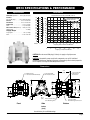
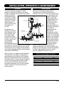
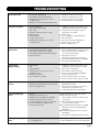
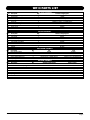
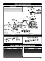
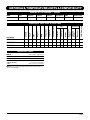
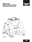
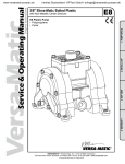
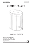
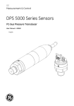
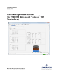
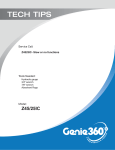
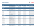
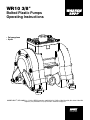
WR10 3/8" Bolted Plastic Pumps Operating Instructions • Polypropylene • Kynar WARREN RUPP®, IDEX AODD, Inc. • A Unit of IDEX Corporation • 800 N. Main St., P.O. Box 1568, Mansfield, Ohio 44901-1568 USA Telephone (419) 524-8388 • Fax (419) 522-7867 • www.warrenrupp.com Operating and Service Manual Model WR10 3/8" Bolted Plastic Pumps Table of Contents Warnings, Cautions & Notices .................................................. 1 Specifications & Performance ................................................... 2 Installation, Operation & Maintenance ...................................... 3 Troubleshooting ........................................................................ 4 Parts List .................................................................................. 5 Pump Drawing, Exploded View ................................................. 6 Materials, Temperature Limits & Compatibility ......................... 7 Declaration of Conformity ......................................................... 8 Notes ......................................................................................... 9 WARNINGS, CAUTIONS & NOTICES Please read all cautions, warnings and notes completely before installation and start-up. It is the responsibility of the purchaser to retain this manual for reference. Failure to comply with the recommendations stated in this manual may damage the pump and void the factory warranty. WARNINGS To prevent static sparking the pump, piping, valves, and containers must be grounded. Fire or explosion can occur when handling flammable fluids and whenever discharge of static electricity is a hazard. Pump exhaust may contain contaminants that can cause serious injury. Take precautions to pipe exhaust away from work area if pumping chemicals, hazardous or flammable materials. CAUTIONS You must check the tightness of all hardware prior to installation. Do not exceed the maximum inlet air pressure as stated on the pump model tag. Maximum temperature limits are based on mechanical stress only. Certain chemicals will significantly reduce maximum safe operating temperatures. For chemical compatibility and temperature limits please refer to the Chemical Resistance Guide. Disconnect the compressed air line to the pump and allow all air pressure to bleed from pump prior to performing any maintenance on the pump. Disconnect all intake, discharge and air lines. Drain the pump and dispose of fluid into a suitable container. Check temperature limits for all wetted components when choosing pump materials. Temperature limits may vary depending on the material. All operators of the equipment should be properly trained to ensure safe working practices. The process fluid and cleaning fluids must be chemically compatible with all wetted pump components. Please refer to the Chemical Resistance Guide for additional information. Never allow the piping system to be supported by the pump manifolds or valve housing. These components are not designed to support structural weight and pump failure may result.. Thoroughly flush pump before installing into process lines. FDA and sanitary approved pumps should be cleaned or sanitized before use. Noise levels can exceed 85 dBA. Always wear ear and eye protection when operating or repairing pumps. NOTICES Blow out air line for at least 15 seconds before attaching to pump to make sure that all debris is removed. Use an in-line air filter. Compressed air should not be applied to the exhaust port. If this happens the pump will not function. Clamp style pumps fitted with PTFE or XLTPE come standard from the factory with expanded PTFE liquid chamber gaskets. PTFE gaskets cannot be reused. Before disassembly of clamp band pumps, mark a line from each liquid chamber to its corresponding air chamber. This will ensure proper alignment when reassembling. Tighten both outer pistons at the same time to ensure a tight fit when installing PTFE diaphragms. See torque settings for additional details. The pump does not require continuous lubrication. Page 1 WR10 SPECIFICATIONS & PERFORMANCE Specifications Performance Displacement Per Stroke, 0.0045 Gal. (0.017 L) 75 70 65 60 55 50 45 40 35 30 25 20 15 10 5 0 Meters 240 220 200 180 160 140 120 100 80 60 40 20 0 Feet 100 1 AIR CONSUMPTION IN SCFM AIR PRESSURE IN PSI 90 Discharge Head in PSI Flow Rate adjustable to . . 0-6.8 gpm (261 lpm) Port Size Inlet and Discharge . . . . . 3/8" Female NPT (BSP) Air Inlet . . . . . . . . . . . . . . . . 0.25" Female NPT Air Exhaust . . . . . . . . . . . . . 0.25" Female NPT Suction Lift . . . . . . . . . . . . . . . 15' (4.57 m) Dry PTFE . . . . . . . . . . . . . . . . . . . . . 11' (3.40 m) Dry Max. Particle Size (Diameter) . . 0.10"(2.25 mm) dB(A) Reading . . . . . . . . . . . . . . . . . . . . 78 dB(A) Shipping Weights Polypropylene . . . . . . . . . . . . . . . 3 lbs (1.40 kg) Kynar . . . . . . . . . . . . . . . . . . . .4.5 lbs. (2.04 kg) 3 80 SCFM M3/HR 1 1.7 3 5.1 5 8.5 70 60 5 50 40 30 20 10 0 0 0 1 2 5 3 5 4 6 7 8 Capacity in U.S. Gallons Per Minute 10 15 20 25 Capacity in Liters Per Minute 30 9 35 CAUTION: Do not exceed 100 psig (6.8 bars) air supply or liquid pressure. CAUTION: Nonmetallic pumps and plastic components are not UV stabilized. Ultraviolet radiation can damage these parts and negatively affect material properties. Do not expose to UV light for extended periods of time. Dimensions 4.09 [104] Opposite Side: 1/4" Female NPT Air Exhaust 3/8" Female NPT Fluid Suction Connection 1/4" Female NPT Air Inlet Connection POLY 5.13 [130] 2.07 [53] 5.32 [135] 2.79 [71] KYNAR 5.08 KYNAR [129] 5.67 [144] 2.07 [53] 0.94 [24] 0.20 [5] Front 15.71 [399] Removable Foot Pad 5/16" Mounting Hole Side POLY 5.72 [145] 3/8" Female NPT Fluid Discharge Connection Bottom Inches [mm] Consult factory for certified drawings. Page 2 INSTALLATION, OPERATION & MAINTENANCE Installation The pump should be mounted in a vertical position. In permanent installations, the pump should be attached to plant piping using a flexible coupling on both the intake and discharge connections to reduce vibration to the pump Air Connection and piping. To further reduce vibration, a surge suppressor next to the pump may be used. Suction pipe size AODD PUMP should be at least the same diameter as the inlet connection size, Manometer even larger if highly Flexible Connection viscous fluid is to be pumped. If suction hose Fluid Inlet is used, it must be of a Shut Off Valve non-collapsible Union or Pipe Flange Connection reinforced type. Discharge piping should be of at least the same diameter as the discharge connection. It is critical, especially on the suction side of the pump, that all fittings and connections are air tight or pumping efficiency will be reduced and priming will be difficult. Make certain the air supply line and connections and compressor are capable of supplying the required pressure and volume of air to operate the pump at the desired flow rate. The quality of the compressed air source should be considered. Air that is contaminated with moisture and dirt may result in erratic pump performance and increased maintenance cost as well as frequent process “down time” when the pump fails to operate properly. Pump Operation The pump is powered by compressed air. Compressed air is directed to the pump air chamber by the main air valve. The compressed air is separated from the Air Exhaust fluid by a membrane called a diaphragm. Pulsation Dampener The diaphragm in turn Discharge Pressure applies pressure on Gauge Flexible the fluid and forces it Connection out of the pump Fluid Discharge discharge. While this is occurring, the opposite Shut Off Valve Union or Pipe Flange air chamber is Connection depressurized and exhausted to Flexible atmosphere and fluid Separator Connection Filter is drawn into the pump suction. The cycle again repeats, thus creating a Air Stop Valve/ Needle Valve constant reciprocating Pressure-reducing Valve action which maintains Air Exhaust Muffler flow through the pump. The flow is always in through the bottom suction connection and out through the top discharge connection. Since the air pressure acts directly on the diaphragms, the pressure applied to the fluid roughly approximates the air supply pressure supplied to the main air valve. Recommended Piping Connections Pump Size 1/4" 3/8" 1/2" 1" 1-1/2" 2" 3" Minimum Air Line Size 1/4" 1/4" 1/2" 1/2" 1/2" 1/2" 3/4" Minimum Suction Line Size 1/4" 3/8" 1/2" 1" 1-1/2" 2" 3" Page 3 TROUBLESHOOTING Symptom Pump cycles once Potential Cause(s) 1 Incorrect pilot o-ring placement 2 Inner diaphragm plate installed backwards 3 Deadhead (system pressure meets or exceeds air supply pressure) 4 Air valve or center block gaskets installed incorrectly Recommendation(s) 1 Reinstall pilot o-rings in correct positions 2 Reinstall inner diaphragm plate correctly 3 Check system for pressure ratio to pump 4 Install gaskets with holes properly aligned Pump will not operate 1 2 3 4 5 6 7 8 Pump is over lubricated Lack of air (line size, PSI, CFM) Worn o-rings Wrong type of lubrication (attack on o-rings) Debris in air valve Clogged manifolds Incorrect o-ring placement Deadhead (system pressure meets or exceeds air supply pressure) 1 1 2 3 4 5 Cavitation on suction side Valve ball(s) not seating properly or sticking Valve ball(s) missing (pushed into chamber) Valve ball(s)/seat(s) damaged or attacked by product Clogged suction line 1 2 Pump cycles and will not prime or flow 2 3 4 5 6 7 8 3 4 5 Pump running sluggish/stalling Product leaking through exhaust 1 5 6 Over lubrication Icing Clogged manifolds Deadhead (system pressure meets or exceeds air supply pressure) Cavitation on suction side Lack of air (line size, PSI, CFM) 1 2 3 Diaphragm failure, or diaphragm plates loose Diaphragm stretched around center hole or bolt holes Excessive air supply pressure 1 1 2 3 4 2 3 4 5 6 2 3 Set lubricator on lowest possible setting or remove • Elima-Matic is designed for lube free operation Check the air line size and length, compressor capacity (HP vs. cfm required) Replace o-rings Check compatibility of o-rings with lubrication Clean air valve/filter Clean suction or discharge manifolds/piping Reinstall o-rings in correct position Increase air supply pressure Check suction condition (move pump closer to product) Clean out around valve ball cage and valve seat area • Replace valve ball or valve seat if damaged • Use heavier valve ball material Worn valve ball or valve seat • Worn fingers in valve ball cage (replace part) Check Chemical Resistance Guide for compatibility Clean suction manifold and/or piping Set lubricator on lowest possible setting or remove • Elima-Matic is designed for lube free operation Clean or replace exhaust muffler Clean manifolds to allow proper air flow Check system to locate deadhead (equilibrium) • Increase air supply pressure Check suction (move pump closer to product) Check the air line size, length, compressor capacity Replace diaphragms, check for damage and ensure diaphragm plates are tight Check for excessive inlet pressure or air pressure • Tighten bolts to recommended torque Check Operating Manual for recommendations Premature diaphragm failure 1 2 3 4 5 6 7 Cavitation Excessive flooded suction pressure Misapplication (chemical/physical incompatibility) Wrong type of lubrication (attack on air side) Incorrect diaphragm plates or plates on backwards Incorrect shaft with corresponding elastomer Start up at full air pressure 1 Enlarge pipe diameter on suction side of pump 1,2 Move pump closer to product • Raise pump/place pump on top of tank to reduce inlet pressure 2 Add accumulation tank or pulsation dampener as close to the pump as possible 3,4 Consult Chemical Resistance Chart for compatibility with products, cleaners, temperature limitations and lubrication 5,6 Check Operating Manual to check for correct part and installation 7 Start up pump slowly (manually or with Smart Start) Breaking and bending shafts 1 2 Build up of solids in water chamber Loose diaphragm plates 1 2 Flush pump, start pump slow Tighten diaphragm plates when replacing diaphragms Page 4 WR10 PARTS LIST Item 1 2 3 4 5 8 9 10 11 Description Air Valve Assembly (Includes items 1-10) Valve Body Valve Spool Valve Spool U-Cup End Cap End Cap O-Ring Air Diverter Valve Insert Valve Gasket Valve Screw Item 12 18 19 20 21 22 25 33 Description Center Section Pilot Shaft Pilot Shaft Spacer Pilot Shaft O-Ring Pilot Shaft Snap Ring Shaft Retainer Shaft Retainer Screw Muffler Item 34 35 37 38 40 Description Main Shaft O-Ring Main Shaft Inner Diaphragm Plate Outer Diaphragm Plate Diaphragm Qty. 2 1 2 2 2 Item 44 45 46 50 51 52 53 60 62 Description Water Chamber Water Chamber Bolt (Long) Water Chamber Bolt (Short) Valve Seat Valve Seat Seal Valve Stem Spring Manifold Foot Pad Qty. 2 4 12 4 8 4 4 2 4 AIR VALVE ASSEMBLY Qty. Standard: Polypropylene 1 E800 1 10-048 1 E500B ASY (Includes (2) P98-104A) 2 P98-104A 2 E800D (Includes (1) E800D ASY) 2 E500E 1 10-075 1 E500H 1 E800J 4 10-050 AIR END ASSEMBLY Qty. Standard: Polypropylene 1 E801A 1 E803A 5 E503C 6 E503B 2 E503D 2 E801B 4 E501C 1 06-034 DIAPHRAGM ASSEMBLY TPE PTFE E503B E503B 10-028 10-028 C126 C126 10-023 (Poly), 10-040 (Kynar) 10-023 (Poly), 10-040 (Kynar) 10-032 (XL) 10-044 (PTFE) WET END ASSEMBLY Standard: Polypropylene Option 1: Kynar 10-002 10-036 10-052 10-052 10-051 10-051 10-022 (Poly) 10-039 (Kynar) 10-073 (XL), 10-045 (PTFE) 10-073 (XL), 10-045 (PTFE) 10-005 10-038 10-030 10-030 10-003 10-037 10-035 10-035 Page 5 WR10 EXPLODED VIEW Torque Settings Water Chamber Bolts Diaphragm Plates — Rubber Diaphragm Plates — PTFE Air Valve Cap Screws 25 in-lbs (2.8 N-m) 40 in-lbs (4.5 N-m) 60 in-lbs (6.8 N-m) 60 in-lbs (6.8 N-m) 25 in-lbs (2.8 N-m) 11 5 2 1 10 DETAIL A 44 46 45 4 8 12 60 in-lbs (6.8 N-m) 3 9 38 40 37 33 34 40 in-lbs (4.5 N-m) 35 DETAIL B Torque Settings 62 DETAIL B Detail B Detail A 60 18 25 51 50 53 52 51 19 20 21 22 WR10 Repair and Maintenance Kits Air End Kit- Part #: E8 AIR KIT Description Valve Spool U-Cup End Cap O-Ring Air Diverter Valve Insert Valve Gasket Pilot Shaft O-Ring Main Shaft O-Ring Qty 2 2 1 1 1 6 2 Part Number P98-104A E500E 10-075 E500H E800J E503B E503B Wetted End Kits Part Number E8P XL KIT E8 G KIT E8P TX KIT Description XL Elastomer Kit Geolast Elastomer Kit PTFE Elastomer Kit Page 6 MATERIALS, TEMPERATURE LIMITS & COMPATIBILITY Materials of Construction — Pumps MODEL ® Acetal Aluminum Cast Iron Hastelloy C WR10 (3/8") Polypropylene PVDF ● ● Stainless Steel DIAPHRAGMS ● VALVE SEATS VALVE SEALS ● ● ● ● (FKM) Fluorocarbon FDA Hytrel® Santoprene (TPE XL) Encapsulated Silicone Thermoplastics FUSION™ Versa-Tuff ™ PTFE Tef-Matic™ 316 Stainless Steel Polyurethane Polypropylene EPDM Neoprene PVDF ELASTOMERS Buna-N Aluminum Diaphragms, Valve Seats & Valve Seals ● Temperature Limits BUNA-N +10°F (-12°C) to +180°F (82°C) PTFE +40°F (+4°C) to +220°F (105°C) SANTOPRENE (TPE XL) -20°F (-29°C) to +300°F (149°C) PLASTIC PUMPS can operate to the following temperature limits: • POLYPROPYLENE 32°F (0°C) to 175°F (79°C) • PVDF 10°F (-12°C) to 225°F (107°C) NOTE: These are average temperatures. Chemicals and solvents can have an effect on temperature limit Page 7 +LJSHYH[PVUVM*VUMVYTP[` >HYYLU9\WW0+,?(6++0UJ54HPU:[YLL[76)V_ 4HUZMPLSK6OPV <:( Certifies that Air-Operated Double Diaphragm Pumps Series: HDB, HDF, M Non-Metallic, S Non-Metallic, M Metallic, S Metallic, T Series, G Series, U Series, EH and SH High Pressure, W Series, SMA and SPA Submersibles, and Tranquilizer Surge Supressors comply with the European Community Directive 2006/42/EC on Machinery, according to Annex VIII. This product has used Harmonized Standard EN 809, Pumps and Pump Units for Liquids - Common Safety Requirements, to verify conformance. Signature of authorized person October 20, 2005 Date of issue David Roseberry Printed name of authorized person Engineering Manager Title Revision Level: C October 13, 2009 Date of revision Kynar is a registered tradename of Penwalt Corp. Warren Rupp is a registered tradename of IDEX AODD, inc. WARREN RUPP, INC. A Unit of IDEX Corporation 800 North Main Street Mansfield, OH 44901-1568 USA (419) 524-8388 Fax: (419) 522-7867 www.warrenrupp.com ©2009 IDEX AODD, Inc. wr10om-1109