1
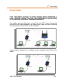
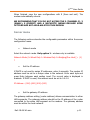
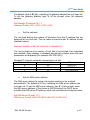
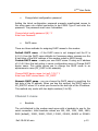
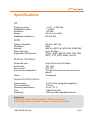
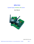
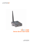
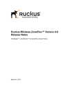
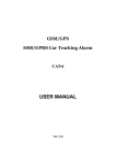
Wifi Modem
User Guide
No part of this document may be reproduced or transmitted (in electronic or
paper version, photocopy) without Adeunis RF consent.
This document is subject to change without notice.
All trademarks mentioned in this guide are the property of their respective
owner.
ADEUNIS RF
283, rue Louis Néel
38920 Crolles
France
Phone
Fax
+33 (0)4 76 92 07 77
+33 (0)4 76 08 97 46
Ref. 09-08-V0-smn
ARF45 User Guide
Table of contents
About this document ........................................................................ 2
Declaration of conformity ................................................................ 3
Overview .......................................................................................... 4
Power supply .................................................................................... 5
Serial link wiring .............................................................................. 6
Connection during serial configuration phase ........................................6
Connection for data transmission .........................................................6
Functionnality .................................................................................. 7
Set-up Mode .......................................................................................7
TCP/IP connections ..............................................................................9
Set-up ............................................................................................ 10
MAC Address menu ........................................................................... 10
Setup menu ...................................................................................... 10
Server menu ..................................................................................... 11
Channel 1 menu ................................................................................ 13
WLAN menu ...................................................................................... 17
Default menu .................................................................................... 23
Exit without save menu ..................................................................... 24
Save and exit menu........................................................................... 24
Recommanded configuration .............................................................. 24
Specifications ................................................................................. 25
Ref. 09-08-V0-smn
p1
ARF45 User Guide
About this document
RF45
This guide describes the A
accessories.
Ref. 09-08-V0-smn
- ARF7532A device, their options and
p2
ARF45 User Guide
Declaration of conformity
Manufacturer’s name:
Manufacturer’s address
ADEUNIS R.F.
Parc Technologique PRE ROUX IV
283 rue Louis NEEL
38920 CROLLES - FRANCE
declares that the product if used and installed according to the user guide available on
our web site www.adeunis-rf.com
Product Name:
Product Number(s):
Product options:
ARF45
ARF7532A
Complies with the RTTE Directive 99/5/EC:
EMC:
EN 301 489
Safety:
Radio:
conformity is proven by compliance to the harmonized standard
conformity to the standard EN 60950-1/2001
conformity is proven by compliance to harmonized standard EN
300-328 covering essential radio requirements of the RTTE
directive.
Exposure to radio frequency signals: Regarding the 1999/519/EC recommendation,
when using the device, keep the product at least 3 cm from your body.
Notes:
- Conformity has been evaluated according to the procedure
described in Annex III of the RTTE directive.
- Receiver class (if applicable): 3.
Crolles, November 6th, 2007
VINCENT Hervé / Quality manager
Download of the user guide
Thank you for having chosen the ADEUNIS RF products.
User guides can be uploaded directly on our web site www.adeunis-rf.com
Index
Products
Paragraph Modems > WIFI modem
Print version available upon request
9
Tel : +33 4 76 92 07 77
9
Email : [email protected]
Ref. 09-08-V0-smn
p3
ARF45 User Guide
Overview
THIS DOCUMENT APPLIES TO WIFI MODEM WITH FIRMWARE V
6.6.0.4 PLEASE CONTACT US FOR THE APPROPRIATE USER GUIDE
IF YOU HAVE A DIFFERENT FIRMWARE VERSION.
The modem converts data from a serial link into TCP frames transported
through the Wifi radio standard to an access point. Data can also be received
from the access point and sent to the serial link.
Communication between two modems is also possible using Wifi ad hoc
mode:
Ref. 09-08-V0-smn
p4
ARF45 User Guide
The operating parameters of these modems (serial link, WIFI and LAN
management…) can be modified through a terminal software using a PC
serial port or a LAN telnet port.
Power supply
To perform wiring of these products, the bottom part of the housing (part
with stuffing box) has to be opened by unscrewing the two stainless steel
screws on each side.
Retirer
les visthese
de la partie
Remove
screws
avec presse étoupe
The ARF 45 product must be supplied from a DC voltage source. This
voltage source must be 8V minimum and must not exceed 30 VDC.
+
GND
RTS
RX
TX
CTS
WLAN
ACT
PWR
+ DC Supply
Ref. 09-08-V0-smn
p5
ARF45 User Guide
Serial link wiring
The WIFI modem serial interface wiring is a two-step connection process:
First connect the modem to a PC to set up the modem configuration,
Then connect the modem to the final equipment for data transmission.
Connection during serial configuration phase
For the initial configuration phase, the WIFI modem has to be connected on
to a PC COM port. The set-up configuration software does not require
RTS/CTS wiring. The following scheme is an example of connection with a
PC:
Modem
(DCE)
+
-
RTS
RX
TX
CTS
WLAN
ACT
PWR
+ DC Supply
5 2 3
SUB-D 9
PC
(DTE)
Connection for data transmission
For the data transmission phase, the WIFI modem is attached by its serial
port to the final transmission equipment. If the hardware flow control has
been selected during modem configuration phase, RTS and CTS lines have to
be connected between both pieces of equipment.
The following scheme is an example where the modem is connected as a
piece of DCE equipment to a DTE with hardware flow control handshake:
Ref. 09-08-V0-smn
p6
ARF45 User Guide
Modem
(DCE)
+
-
RTS
RX
TX
CTS
WLAN
ACT
PWR
+ DC Supply
5
7 2 3 8
SUB-D 9
PC
(DTE)
Functionnality
ARF 45 WIFI modem allows data transfer from a serial link over a WIFI
network to an access point. The WIFI modem can be seen as a R232/WIFI
gateway.
Set-up Mode
The modem set-up mode can be entered using a terminal software. This is
the only way to configure the modem.
Accessing modem set-up by serial port
The modem setup can be reached with any terminal configured with the
following settings: 9600 baud, 8 bits, no parity, 1 stop bit, no flow control
and no local echo.
Then, reset the modem by cycling the unit’s power (turning the power off
and back on). Immediately upon resetting the modem, enter three lowercase
x characters (xxx).
The three xxx characters must be entered within three seconds after
resetting the modem.
Ref. 09-08-V0-smn
p7
ARF45 User Guide
If the xxx are correct the MAC address menu is displayed.
AFTER POWER-UP, NO CHARACTERS MUST BE TRANSMITTED ON
THE SERIAL LINK DURING A MINIMUM DELAY OF 5 SECONDS TO
ENSURE PROPER BOOT OPERATION OF THE MODEM.
See chapter SETUP for the description of the configuration menus.
Accessing modem set-up by telnet port
The telnet set-up mode can only be entered if a minimal LAN configuration
has been previously introduced by serial port setup to meet the
characteristics of the LAN and WIFI access point from where the modem is
accessed. This minimal configuration includes the WLAN name, the
encryption mode and the associated key for the Wireless parameters and the
IP address of the modem on LAN with manual IP attribution (when NO DHCP
server on the LAN), the subnet mask and the gateway if any required for the
Ethernet parameters.
The only case in which the first setup phase can be bypassed is when the
modem is powered up for the first time, the Access point on which it is
connected has no WEP key configured and a DHCP server is found on the
LAN. Only in this special case, the modem can be accessed with an access
point by WIFI, TCP-IP and Telnet protocols without any initial configuration.
When a modem is configured in DHCP mode, its IP address can be
determined by the “LANTRONIX device installer” utility. It browses the LAN
searching for WIFI modem and displays the MAC address and IP address of
each modem found. The association is realized with the MAC address which
can be found on the rear of the modem box.
The modem setup can then be reached using a telnet terminal to connect on
the port 9999 of the modem. Under a Windows station, the following line can
be entered from a DOS command windows: telnet 192.168.0.1 9999
(where 192.168.0.1 must be replaced by the IP address of your modem)
See chapter SETUP for the description of the configuration menus.
Lost of connection during telnet set-up phase
In case of LAN disconnection (LAN cable disconnected during set-up phase),
the TCP connection is disconnected on the PC. The internal set-up of the
modem is no more accessible through the network while its internal TCP
Ref. 09-08-V0-smn
p8
ARF45 User Guide
connection time out is not reached. Once internal timeout reached (the
internal timeout of the modem is fixed to 5 minutes), the connection is
released from the modem side and the modem is ready to receive a new
incoming set-up connection.
Transmission Mode
The data transmission is performed through the wireless LAN using TCP-IP
protocol. The modem is ready to send or receive data when it leaves its setup phase.
AFTER POWER-UP, NO CHARACTERS MUST BE TRANSMITTED ON
THE SERIAL LINK DURING A MINIMUM DELAY OF 5 SECONDS TO
ENSURE PROPER BOOT OPERATION OF THE MODEM.
Connection of the modem on a remote server
The modem acts as a client. It is ready to establish a remote connection after
a delay of 5 seconds after a power-up or a set-up configuration phase.
The following behaviour can only be expected if the recommended settings
have been set on the modem (see chapter SET UP). The TCP communication
is established by the modem when it receives any character from its serial
link. On the first character reception, the modem tries to connect on the
remote server specified by the remote IP and the remote port and data are
transmitted. If the remote server cannot be reached, data sent on the serial
link are kept in the internal modem buffer (in the limit of its size) and are
sent when the modem finally succeeded in connecting to the host.
The connection remains active while the modem is powered. If the host side
disconnects, the modem re-attempts to connect until the connection to the
host is successful.
Connection of a client on the modem
The modem acts as a server while it is powered. The modem is ready to
accept an incoming connection after a delay of 8 seconds after power-up or a
set-up configuration phase. There is no password to connect to the modem.
The connection is never closed by the modem.
Ref. 09-08-V0-smn
p9
ARF45 User Guide
Set-up
After entering the setup mode either by telnet mode or by RS232 link, the
following message appears on the terminal.
MAC Address menu
MAC address 00204A895D35
Software version V6.6.0.4 (090203)
Press Enter for Setup Mode
At this stage, press Enter within 5 seconds to enter the setup menu.
The configuration settings is displayed, followed by the setup menu options
Setup menu
Change Setup:
0 Server
1 Channel 1
2 Channel 2
3 E-mail
4 WLAN
5 Expert
6 Security
7 Defaults
8 Exit without save
9 Save and exit
Your choice ?
Select an option on the menu by entering the number of the option and press
Enter.
You can view the current configuration by only pressing Enter.
To enter a value for a parameter, type the value and press Enter. To confirm
a current value, press Enter (without input parameters).
Ref. 09-08-V0-smn
p 10
ARF45 User Guide
When finished, save the new configurations with 9 (Save and exit). The
modem automatically reboots.
WE RECOMMEND THAT YOU DO NOT ACCESS THE 2 (CHANNEL 2), 3
(EMAIL), 5 (EXPERT) AND 6 (SECURITY) MENUS BECAUSE SOME
OPTIONS ARE NOT AVAILABLE FOR THIS MODEM.
Server menu
The following sections describe the configurable parameters within the server
configuration menu.
•
Network mode
Select the network mode. Only option 1 : wireless only is available.
Network Mode (0=Wired Only 1=Wireless Only 2=Bridging(One Host) ): (1)
?
•
Set the IP address
If DHCP is not used to assign IP addresses, enter it manually. The modem IP
address must be set to a unique value in the network. Enter each byte and
press Enter between each section input. The current value is displayed in
brackets. If DHCP is used, this address must be set to 0.0.0.0.
IP Address : (000) (000) (000) (000)
•
Set the gateway IP address
The gateway address setting (router address) allows communication to other
LAN segments. The gateway address should be the IP address of the router
connected to the same LAN segment as the modem. The gateway address
must be within the local network.
Ref. 09-08-V0-smn
p 11
ARF45 User Guide
The default value is N (No), indicating the gateway address has not been set.
To set the gateway address, type Y. At the prompt, enter the gateway
address.
Set Gateway IP Address (N) ? Y
Gateway IP addr (000) .(000) .(000) .(000)
•
Set the netmask
The net mask defines the number of bits taken from the IP address that are
assigned for the host part. The net mask is entered under IP address format
(decimal values).
Netmask: Number of Bits for Host Part (0=default) (8)
The unit prompts for the number of host bits to be entered, then calculates
the netmask, which displays in standard decimal dot notation when the save
parameters are displayed (for example 255.255.255.0).
Standard IP network netmasks representing host bits
Network class
Host bits
A
24
B
16
C
8
•
Netmask
255.0.0.0
255.255.0.0
255.255.255.0
Set the DNS server address
The DNS server allows the name of a remote machine to be resolved
automatically. The default is N (No), indicating the DNS server address has
not been set. To set the DNS server address, type Y. At the prompt, enter
the DNS server address. If the device is DHCP enabled, the DHCP server
provides the DNS server IP address, which will override this configured value.
Set DNS Server IP addr (Y) ?
DNS Server IP addr (000) 192.(000) 168.(000) 0.(000) 100
Ref. 09-08-V0-smn
p 12
ARF45 User Guide
•
Change telnet configuration password
Setting the telnet configuration password prevents unauthorized access to
the setup menu via a telnet connection to port 9999. Type Y and enter the
password. The password must have 4 characters.
Change telnet config password (N) ? Y
Enter new Password:
•
DHCP name
There are three methods for assigning DHCP names to the modem.
Default DHCP name : if the DHCP name is not changed and the IP is
0.0.0.0, then the DHCP name defaults to Cxxxxxxxx where xxxxxxxx are the
8 last bytes of the MAC address of the modem coded in ASCII format.
Custom DHCP name : create your own DHCP name. If using an IP address
of 0.0.0.0 then the last option in server configuration menu is Change DHCP
device name. This option allows you to change the DHCP name to an
alphanumeric name (MY_DHCP in the example).
Change DHCP device name (not set) ? (N) ? Y
Enter new DHCP device Name : MY_DHCP
Numeric DHCP name : you can change the DHCP name by specifying the
last byte of the IP address. When you use this method, the DHCP name is
MY_DHCPYY where YY is what you choose for the last byte of the IP address.
This method only works with two digits numbers (0 to 99).
Channel 1 menu
•
Baudrate
The unit attached to the modem must agree with a baudrate to use for the
serial connection. Valid baudrate values are 300, 600, 1200, 2400, 4800,
9600 (default), 19200, 38400, 57600, 115200, 230400, 460800 or 921600.
Ref. 09-08-V0-smn
p 13
ARF45 User Guide
The current value is displayed in brackets. This value does not apply for the
setup mode which can only be entered at 9600 bps.
Baudrate (9600) ?
•
I/F (interface) mode
The interface (I/F) mode is a bit-coded byte entered in hexadecimal notation.
The current value is displayed in brackets. In the example below 4C means :
8 bits, no parity, 1 stop.
I/F Mode (4C) ?
The following table displays available options :
I/F mode option
RS232
7 bits
8 bits
No parity
Even parity
Odd parity
1 stop bit
2 stop bits
•
7
6
5
0
1
0
0
1
4
3
2
1
1
0
1
1
0
0
0
0
1
1
1
1
Flow
Flow control sets the local handshaking method for stopping serial
input/output. The current value is displayed in brackets.
Flow (00) ?
The following table displays available options:
Flow control option
No flow control
XON/XOFF flow control
Hardware handshake with RTS/CTS lines
Ref. 09-08-V0-smn
Hex
00
01
02
p 14
ARF45 User Guide
•
Port number
The port number setting is used in TCP connection. It is the channel for
connection initiated by a remote client.
Packets sent to the modem with this port number are received on this
channel.
The port number setting is used as source port number for outgoing packets.
The current value is displayed in brackets.
Port No (10001) ?
The following TCP ports are reserved and must not be used:
1-1024, 9999, 14000-14009, 30704 and 30718.
•
Connect mode
Connect mode defines the modem connection method and its reaction to
incoming and outgoing connections over the network. The current value is
displayed in brackets.
ConnectMode (C1) ?
Enter connect mode options in hexadecimal notation:
The following table displays available options:
connect mode option
Never accept incoming
Always accept
Connect on a remote
server on RS232
character reception
7
0
1
6
0
1
5
0
0
4
0
0
0
3
2
1
0
0
0
0
1
+++ sequence in modem mode
Disable or enable the WiPort’s ability to send the escape sequence. The
default is Y (Yes) (send the escape sequence).
Send '+++' in Modem Mode (Y) ?
Ref. 09-08-V0-smn
p 15
ARF45 User Guide
Show IP address after RING
Disable or enable the WiPort's ability to show the IP address after RING in
Modem Mode. The default is Y (Yes) (shows the IP address).
Show IP addr after 'RING' (Y) ?
•
Autoincrement source port
Y (Yes) auto increment the source port. The WiPort increments the port
number used with each new connection.
Auto increment source port (N) ?
•
Remote IP address
The remote IP address is the destination address used to perform an
outgoing connection.
Remote IP Address : (000) .(000) .(000) .(000)
•
Remote port
The remote TCP port number is used in TCP connections. It is the port
number used for modem initiated connections to make outgoing connections.
This parameter defines the port number on the target host to which a
connection is attempted. The current value is displayed in brackets.
Remote Port (0) ?
•
DisConn mode
Do not change the value 00 for DisConn mode.
DisConnMode (00) ?
Ref. 09-08-V0-smn
p 16
ARF45 User Guide
•
Flush mode
Do not change the value 00 for flush mode.
FlushMode (00) ?
•
DisConnTime (inactivity Timeout)
Use this parameter to set an inactivity timeout. The modem drops the
connection if there is no activity on the serial line before the set time expires.
Enter time in the format mm:ss, where mm is the number of minutes and ss
is the number of seconds.
DisConnTime (00:00) ?
To disable the inactivity timeout, enter 00:00.
Send char 1/2
Do not change the value 00 for Send char 1 and Send char 2
SendChar 1 (00) ?
SendChar 2 (00) ?
WLAN menu
Topology
Select infrastructure (ESS) mode or adhoc (IBSS) mode. Infrastructure mode
communicates with access points. Adhoc mode communicates directly only
with other modems.
Topology 0=Infrastructure, 1=AdHoc (0) ?
Network name (SSID)
Ref. 09-08-V0-smn
p 17
ARF45 User Guide
The WLAN name is the name of the WIFI network in which the modem
resides. The current value is displayed in brackets.
Network name (SSID) (ARF_WIFI) ?
Adhoc Network channel
When adhoc is selected in the topology parameter and the modem cannot
find the specified network, the modem switches to Adhoc mode using the
channel value specified.
Channel (11) ?
Security
The modem features WEP and WPA to secure all wireless communication.
WPA and WPA2 are not available when adhoc is selected as the topology.
Security 0=none, 1=WEP, 2=WPA, 3=WPA2/802.11i (0) ?
WEP
Security 0=none, 1=WEP, 2=WPA3, 3=WPA2/802.11i (1) ? 1
Authentication 0=open/none, 1=shared (1) ? 0
Encryption 0=WEP64, 1=WEP128 (0) ?
Display current key (N) ? Y
00 00 00 00 00
Change Key (N) ? Y
Key type 0=hex, 1=passphrase (0) ? 1
Enter Key:
TX Key index (1) ?
Authentication selects whether the encryption keys are matched
(1=shared) with those of the communication partner before passing through
messages or not (2=open/none).
Ref. 09-08-V0-smn
p 18
ARF45 User Guide
The Encryption prompt requests the length of the encryption key and the
security strength. WEP64 uses a 40 bits/5 bytes (option 0). WEP128 uses a
104bits/13 bytes key (option 1).
Select (Y) yes at the display current key prompt to show the currently
configured key/passphrase.
Change key permits modifying the currently configured key by selecting (Y)
Yes.
The key type requests whether the new key is in hexadecimal or passphrase
format.
Enter key prompts for the new encryption key. The passphrase input is not
the same as ASCII input. ASCII is directly translated into hexadecimal bytes
according to the ASCII table. The passphrase is hashed using specific
algorithms.
The passphrase input is safer because it up to 63 chars long. ASCII input is
a maximum of 5 (WEP64) or 13 (WEP128) characters long and limits the
number of combinations.
The TX Key index selects the WEP key used for transmissions. Enter a value
from 1
to 4.
WPA
Only Pre-Shared Keys (PSK) are available for authentication.
Security 0=none, 1=WEP, 2=WPA, 3=WPA2/802.11i (1) ? 2
Group encryption 1=WEP64, 2=WEP128, 3=TKIP (0) ? 3
Display current key (N) ? Y
12345
Change Key (N) ? Y
Key type 0=hex, 1=passphrase (1) ? 0
Enter Key:
Encryption: 0=TKIP, 1=TKIP+WEP (1) ?
Ref. 09-08-V0-smn
p 19
ARF45 User Guide
Set the group encryption type to 1 (WEP), 2 (WPA) or 3 (WPA2). The group
encryption for all wireless devices communicating with the same access point
must be equal to receive broadcast and multicast messages. If any of these
devices are WEP only (no support for WPA) set the group encryption to WEP
for all devices.
Select (Y) yes at the display current key prompt to show the currently
configured key/passphrase.
Change key permits modifying the currently configured key by selecting (Y)
Yes.
The key type requests whether the new key is in hexadecimal or passphrase
format.
Enter key prompts for the new encryption key. The passphrase input is not
the same as ASCII input. ASCII is directly translated into hexadecimal bytes
according to the ASCII table. The passphrase is hashed using specific
algorithms.
Set the Encryption type to the minimum required security level. The “+”
sign
indicates that the group (broadcast) encryption method is different from the
pairwise
(unicast) encryption (i.e. WEP and TKIP).
WPA2 / 802.11i
Only Pre-Shared Keys (PSK) are available for authentication. The
WPA2/802.11i mode is compliant with the Robust Secure Network that is
specified in the IEEE standard 802.11i. It enables the AES-based strong
CCMP encryption.
Security suite: 0=none, 1=WEP, 2=WPA, 3=WPA2/802.11i (2) ? 3
Display current key (N) ? Y
AD 76 08 97 46 00 00 00 00 00 00 00 00 00 00 00 00 00 00 00 00 00 00 00
00 00 00 00 00 00 00 00
Change Key (N) ? Y
Key type 0=hex, 1=passphrase (0) ? 1
Ref. 09-08-V0-smn
p 20
ARF45 User Guide
Enter Key:
It is strongly recommended to use a passphrase of 20 chars or more!
Encryption: 0=CCMP, 1=CCMP+TKIP, 2=CCMP+WEP, 3=TKIP, 4=TKIP+WEP
(4) ?
Select (Y) Yes at the Display current key prompt to show the currently
configured
key/passphrase
Change key permits modifying the currently configured key by selecting (Y)
Yes.
The Key type requests whether the new key is in hexadecimal or passphrase
format.
Enter key prompts for the passphrase. The maximum length is 63
characters.
Lantronix recommends using a passphrase of 20 characters or more for
maximum
security.
Set the Encryption type to the minimum required security level. The “+”
sign
indicates that the group (broadcast) encryption method is different from the
pairwise
(unicast) encryption. For example, for CCMP+TKIP, CCMP is the pairwise
encryption
and TKIP is the group encryption.
Fixed or automatic data rate for radio transfer
The modem permits the control of the transmission rate. Select 0 to set a
fixed data rate or select 1 to set an automatic data rate. The default is 1
(auto). If the TX data rate is set to auto the modem data rate is the
maximum data rate.
TX Data rate 0=fixed, 1=auto fallback (1) ?
Transmission data rate
Ref. 09-08-V0-smn
p 21
ARF45 User Guide
If the above TX Data rate is set to fixed, the selected data rate is the modem
fixed transmission rate. If the above TX Data rate is set to auto, the selected
data rate is
the WiPort’s maximum data rate. Lower data rates allow for larger distances.
It may
also be required when communicating with older devices.
TX Data rate 0=1, 1=2, 2=5.5, 3=11
4=18, 5=24, 6=36, 7=54 Mbps (7) ?
Enable power management
This allows the software to turn off the radio when expecting not to receive
or transmit soon. This features reduces the power consumption of the
modem.
Enabling power management increases the response time, because the radio
needs start up again. The radio is enabled to synchronize and check for
incoming messages (every 100 ms).
This option is not available when the topology is set to Adhoc.
Enable power management (N) ?
Enable Roaming :
If enabled, SmartRoam manages the dynamic list of APs belonging to the
same network as the AP to which the WiPort is currently associated and
stores relevant selection criteria for this list. The WiPort uses these criteria to
identify a candidate AP. If the candidate AP is not the current one, the WiPort
dissociates from the current AP and associates to the candidate.
The roaming technology also triggers candidate selection if the WiPort
reaches the boundaries of good signal coverage for the current AP instead of
waiting until signal quality degrades substantially.
Choose to enable Y (Yes) or disable N (No) No Lantronix's Smart Roam
technology. The default value is N.
Enable Soft AP Roaming (N) ?
Ref. 09-08-V0-smn
p 22
ARF45 User Guide
Default menu
This “default” item of the menu resets some parts of “channel 1”
configuration, “channel 2” configuration, “email” settings, “expert” and
“security” settings to the factory default settings.
The settings for IP address, gateway IP address, netmask, network mode,
topology and wireless security settings remain unchanged.
The specific settings modified by the “default” option are listed below.
Server configuration
All parameters
Channel 1 configuration
Baudrate
I/F mode
Not changed
Send +++ in modem mode
Show IP address after ‘RING’
Auto increment source port
All other parameters
9600
4C (1 stop bit, no parity, 8 bit, RS232, no flow
control)
10001
C0 (always accept incoming connection; no
active connection startup)
Y
Y
N
0
WLAN configuration
Topology
Network name
Channel
Security
Authentication
TX Data rate
TX Data rate
Enable power management
Enable Soft AP Roaming
Ad-Hoc
Not changed
Not changed
Not changed
Not changed
1 (auto fallback)
Not changed
N (No)
Not changed
Port No
Connect mode
Ref. 09-08-V0-smn
p 23
ARF45 User Guide
AFTER
APPLYING
THIS
COMMAND,
THE
RECOMMENDED
CONFIGURATION MUST BE MANUALLY RE-ENTERED. SEE CHAPTER
RECOMMENDED CONFIGURATION.
“Exit without save” menu
Exit the configuration mode without saving any changes and reboot.
“Save and exit” menu
Exit the configuration mode save all changes and reboot. All values are
stored in non volatile memory.
Recommanded configuration
We recommend that after the default menu has been entered or for the first
configuration that you change the following parameters in the Channel 1 and
WLAN menus:
Channel 1 configuration
Connect mode
WLAN configuration
Topology
Soft AP roaming
Ref. 09-08-V0-smn
C1 : always accept incoming connection with any
character
Infrastructure
Enable soft AP roaming
p 24
ARF45 User Guide
Specifications
RF
Frequency range
Radiated RF power :
Sensitivity :
Range :
Standards compliance :
: 2.412 – 2.484 GHz
+ 15 dBm
- 82 dBm
200 m in free field
EN 300-328
WIFI
Network standard :
Modulation :
Security :
Radio data rate :
Supported LAN Protocols :
802.11b; 802.11g
DSSS
WEP 64, WEP 128, WPA-PSK, WPA2-PSK
Up to 54 Mbps
TCP-IP, DHCP, BOOTP, ICMP, ARP, UDP,
SMTP, TFTP, ICMP, SNMP, Auto IP
Modem interface
Serial data rate :
Serial ports :
Flow control :
Set-up and configuration :
Mode :
From 300 bps to 921.6 Kbps
TxD, RxD.
RTS, CTS
Through set-up menus (by serial link or
telnet)
Transparent
General information
Power supply :
Max Consumption
Operating temperature :
Size :
Packaging :
8 to 30 Volts (integrated regulator)
700 mA
-20 to +70 °C
145x100x40 mm
IP65 box with integrated antenna
References
ARF7532A: Basic WIFI modem in IP65 box version
ARF7532B: Advanced WIFI modem in IP65 box version
Ref. 09-08-V0-smn
p 25