1
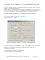
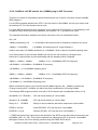
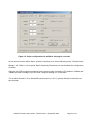
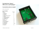
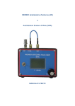
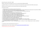
User Guide for PE0FKO v15.10 & v15.11 Firmware
SoftRock v9.0 RX, USB to I2C Interface and SDR-Kits USB Synth
Bob G8VOI (September 2009)
Contents
Section
1
2
3
4
5
6
7
8
9
10
11
12
13
14
15
16
17
18
19
20
Issue 1.1
Description
Introduction
Glossary of Abbreviations Used
Frequently Asked Questions
Using Winrad to access the firmware configuration screens
Firmware Default Settings
General Tab
USB Tab
Si570 Tab
LO Tab - Default state for SoftRock v9.0 RX
LO Tab - Setting up for use with VHF Receive Converters
BPF Tab
BPF Tab - Use with original 'Option 2' BPF 6m filter construction.
ABPF Tab
Calibrate Tab
Test Tab
About Tab
Disclaimer
Copyright
Errors or Suggestions
Document Revisions
PE0FKO Firmware User Guide – G8VOI Issue 1.1 September 2009
Page
2
4
5
8
12
13
14
15
17
18
36
37
38
40
41
42
43
43
43
44
Page 1 of 44
1: Introduction
From the number of requests frequently made on the Yahoo SoftRock forum for details of how to
configure the firmware used in the Atmel ATtiny 45 or 85 AVR device, for use with the various
SoftRock modules, it became apparent that there was a need for a comprehensive 'User Guide'.
This is my attempt to provide such a document to meet that need.
This guide is aimed at the users of both v15.10 and v15.11 of Fred PE0FKO's firmware.
These essentially are the same, apart from the newer version having a minor 'bug' corrected.
Note: this correction only affects users wishing to use the v9.0 Receiver along with the plug-in 2m VHF
Converter, and specific SDR programs, Winrad v1.32, WinradHD (versions prior to v 0.0.7) and
FlexRadio's PSDR v1.16.2 and v1.18.
For all other uses, both versions are fully functional and compatible.
All reference to the 'firmware' will assume either version, unless there is a specific comment to the
contrary.
Major features of the versions of the firmware covered by this User Guide are:
Automatic Band Pass Filter mode within the firmware for compatibility with all SDR programs
Smooth Tuning of the Si570 implemented within the firmware removing tuning glitches
Extensive manipulation of the frequency generated by the Si570 possible
Common calibration feature, a correction factor stored and applied automatically
Much of the information contained within this document, will probably only be of passing interest to the
majority of SoftRock users, however if you wish to go beyond the basic 'default' settings needed for
use with the SoftRock v9.0 Receiver, then hopefully you will find the answers to your questions.
This is aimed to be a 'fluid' document, and therefore will hopefully continue to evolve and be expanded
as any feedback or comments are received.
In some areas involving the calculation and manipulation of the Si570 frequency, the explanation
provided is limited by my own personal difficulties understanding this, however examples will be given
to provide solutions for all common uses. These have been fully tested using the SDR-Kits USB
Synthersizer with a frequency counter monitoring the output.
I am sure for those who require a more detailed explanation, Fred would be willing to discuss the finer
points of the software features and development, and explain the reasoning behind it.
My approach is purely from a 'users' point of view, i.e. how do I configure it to do this?
I only have limited knowledge and understanding of the operating software used within the controller.
PE0FKO Firmware User Guide – G8VOI Issue 1.1 September 2009
Page 2 of 44
My personal thanks and appreciation go to Fred PE0FKO for his magnificent contribution, both in the
development of the firmware, plus his commitment to continue to support and push it forward.
Additionally, for his patience in guiding me through areas where I have had extreme difficulty in
understanding.
The contribution made by Tom DG8SAQ with the creation of the original version of the firmware and
USB Synthersizer, and the subsequent developments made by Jan G0BBL and the QRP2000 group
members is also fully recognised and appreciated.
Without their effort and support, it is unlikely we would now have the superb range of hardware at our
disposal.
Finally, of course, it would be totally remiss of me not to mention and thank Tony, KB9YIG.
Without his tireless work to bring these designs into fruition and produce the excellent kits at such a
low cost, none of this would have been possible.
The contribution to promote the awareness and give hands on experience of SDR through the
SoftRock kits has been truly amazing.
You only need to look at the 6600+ membership of the Yahoo SoftRock40 group, and the spread of
those around the globe to appreciate the exceptional contribution he has, and continues to make.
His induction to the 'QRP Hall of Fame' earlier this year at Dayton was a hugely deserved recognition
of this contribution.
Thanks all,
73, Bob G8VOI
To purchase SoftRock kits, visit Tony Park's website:
http://www.kb9yig.com/
For complete build instructions and further details of the SoftRock kits, visit Robby WB5RVZ's website:
http://www.wb5rvz.com/sdr/index.html
For details or purchasing the SDR-Kits USB Synthersizer, visit Jan G0BBL's website:
http://www.sdr-kits.net/
For further details of Fred PE0FKO's firmware and supporting dll files, visit his website:
Firmware:
http://home.ict.nl/~fredkrom/pe0fko/SR-V9-Si570/
Winrad DLL file:
http://home.ict.nl/~fredkrom/pe0fko/ExtIO_Si570/
PE0FKO Firmware User Guide – G8VOI Issue 1.1 September 2009
Page 3 of 44
2: Glossary of Abbreviations and Terms used
ABPF
Automatic Band Pass Filter, referring to a mode of operation of the v9.0 electronically
switched filter module.
ATtiny45/85
The range of Atmel controllers used for the SoftRock kits.
The only difference is the program memory capacity (4k / 8k)
Atmel
Commercial manufacturer of the micro-controller used
AVR
AdVanced Risc architecture (my best guess)
BPF
Band Pass Filter
DLL
Dynamic Link Library, software program that is common can be shared between
Software applications
Firmware
The program running within the AVR micro-controller
IF
Intermediate Frequency
I2C
Inter IC bus and communication architecture
LO
Local Oscillator
PSDR
PowerSDR Software, originated by FlexRadio
RISC
Reduced Instruction Set Code
SDR
Software Defined Radio
Si570
Silicon Labs I2C programmable versatile oscillator used in the SoftRock designs
SoftRock
The series of SDR kits created and supplied by Tony Parks KB9YIG
USB
Universal Serial Bus, in the context of this guide
VHF
Very High Frequency, in this guide referring to 50MHz and above
v1.4
The original firmware used from Tom DG8SAQ
v2.0
The first updated firmware version from Jan G0BBL and the QRP2000 group for the
v9.0 RX to provide BPF control and smooth tuning using an external dll file
v6.3 TX/RX
SoftRock Transceiver kit covering 1.8 - 30MHz using plug-in modules
v8.3 RX
SoftRock Receiver kit, the USB to I2C interface can be used as a controller
v9.0 RX
SoftRock Receiver kit covering 1.8 - 30MHz with USB control
v15.xx
Versions of Fred PE0FKO firmware for the ATtiny 45 / 85
PE0FKO Firmware User Guide – G8VOI Issue 1.1 September 2009
Page 4 of 44
3: Frequently Asked Questions
The following questions have appeared on the Yahoo Softrock40 forum at some point in time, and
hopefully will be answered in this section, or by pointing to the appropriate set up tab needed.
Q1: Why do I need to use Winrad, as I do not want to use that SDR program?
There is actually no need for you to have any interest in using Winrad for your normal SDR operating,
however at the present time, it is used as the 'vehicle' to access to the set-up pages needed for the
Atmel AVR firmware.
Once the firmware has been configured for your use, there is no need to ever run Winrad again.
If you need to make any further changes to the firmware set-up, you will need to have Winrad
available to run again.
Fred PE0FKO originally created an external dll file to support using Winrad with the USB controlled
Si570 based SoftRock v9.0 Receiver, and this is used to access the firmware set-up.
See details in Section 4 of how to obtain the dll file needed and how to use it with Winrad.
Q2: Which version of the firmware do I have?
The version of the firmware you have is displayed on the opening 'General' tab of the set-up screens.
All available versions of the AVR firmware are correctly recognised, however some options and
functions are unique to the PE0FKO versions and therefore will be 'greyed out' and not available when
using the earlier versions.
v1.4 Firmware (ATtiny45) by Tom DG8SAQ
This is the original firmware version created by Tom, DG8SAQ and supplied with the QRP2000
group's USB Synthersizer, available from Jan G0BBL.
Tony adapted this design originally for both the SoftRock v9.0 RX and the USB to I2C interface, and
continued to supply this with the USB to I2C interface until changing over to v15.10 firmware late in
July 2009.
v2.0 Firmware (ATtiny85) by Jan G0BBL and the QRP2000 group
This version was introduced in February 2009, specifically to provide support for the switched BPF
module for the v9.0 designed by Jan G0BBL. In addition it implemented 'smooth tuning' of the Si570,
supported by a modified version of the SDR1kUSB.dll file by Guido PE1NNZ.
This version was supplied until Tony adopted Fred PE0FKO's firmware for the v9.0 RX early in June
2009.
Continued on the next page:
PE0FKO Firmware User Guide – G8VOI Issue 1.1 September 2009
Page 5 of 44
v15.xx Firmware (ATtiny 45 or 85) by Fred PE0FKO
Fred identified a 'bug' in the original firmware that was responsible for the majority of the USB related
difficulties experienced by many builders. This set in motion his continued development to enhance
and add additional features, building on the previous versions, to provide the current extremely flexible
firmware now available. This development continues, and the next version is already under initial
testing, supporting even greater flexibility.
Q3: How do I get the latest version of the firmware?
It is possible to purchase the Atmel ATtiny chip ready programmed from Cecil, K5NWA via his
website, you need to specify the device (ATtiny 85) and the version of the firmware you require
programming.
http://www.softrockradio.org/catalog/32/microcontrollers
It might be worth making an enquiry on the Yahoo 'SoftRock40' forum if anyone local to you has the
facilities available to program a device, you never know!
Q4: How do I program my own chip?
You can program your own device using very simple hardware, provided that it is either a new device,
or it has not been previously programmed for use with a SoftRock.
Full details of the hardware and software needed to program your own chips are available in my
'Beginners Guide to Programming the Atmel Devices':
http://home.ict.nl/~fredkrom/pe0fko/g8voi/
You can download the hex files needed to program the device from Fred's website, both ATtiny 45 and
85 versions exist:
http://home.ict.nl/~fredkrom/pe0fko/SR-V9-Si570/
Q5: Which Atmel ATtiny device should I use?
The current v15.10 and v15.11 versions of the firmware just fit in the smaller capacity ATtiny45 device
(4k), however there is no spare room available for any future enhancements.
The next planned release of the firmware (v15.12) will not fit in the smaller device, therefore it is
recommended to use the ATtiny 85 device (8k), to allow it to be reprogrammed at a later date.
Tony KB9YIG is supplying the current version of the firmware using the ATtiny85.
PE0FKO Firmware User Guide – G8VOI Issue 1.1 September 2009
Page 6 of 44
Q6: Can I use this firmware with my SoftRock v6.3 TX / RX?
Both v15.10 and v15.11 firmware is fully compatible with the USB to I2C interface used with the v6.3
SoftRock TX / RX, however you will need to modify the default settings.
These defaults configure the device for use with the v9.0 RX (also suitable for the v8.3 RX, using the
USB to I2C interface). This has the switched BPF control lines active.
To use the firmware with the v6.3 TX / RX, all that is necessary is to disable the 'ABPF' function.
See Section 13 'ABPF' for further details.
Once the USB is disconnected and re-connected, the CW Key / Paddle inputs and PTT output lines
become active.
Q7: My Key / CW paddles and PTT line do not operate properly?
See answer to Question 6, or go to Section 13 'ABPF'
Q8: Can I use the firmware with my SDR-Kits USB Synthersizer?
The firmware is compatible with the SDR-Kits USB Synthersizer, see Questions 6 and 7, and details in
Section 13.
Q9: How do I set it up to use the SoftRock v9.0 and 6m BPF option?
The firmware can be used with the 'Option 2' BPF module filter configuration, however there are some
restrictions.
Please see further information regarding this subject in Section 12, ideally before you have started to
construct your filter module.
Q10: What DLL files do I need to use with the various SDR programs?
For Winrad v1.32, v1.42 and WinradHD:
ExtIO_Si570.dll must be placed in the folder containing the Winrad Program.
See Section 4 for further details.
Rocky v3.6: No additional DLL file needed.
PowerSDR v1.90 sr40 (Guido PE1NNZ): No additional DLL file needed
PowerSDR-IQ v1.12.20 (Christos SV1EIA): No additional DLL file needed
PowerSDR v1.16.2 / v1.18 (FlexRadio): PE0FKO modified version of SDR1kUSB.dll required.
This can be downloaded from the following link and placed in the folder where the program is installed.
http://home.ict.nl/~fredkrom/pe0fko/SR-V9-Si570/
PE0FKO Firmware User Guide – G8VOI Issue 1.1 September 2009
Page 7 of 44
4: Using Winrad to access the firmware configuration screens
At the present time it is necessary to use the Winrad SDR program with Fred's supporting dll file in
order to access the firmware set up pages. In the near future the 'CFGSR' stand alone program could
be used instead to access the firmware set up pages.
Any of the following versions of Winrad can be used:
Winrad v1.32 - Alberto I2PHD
http://www.weaksignals.com/
Winrad 1.42 - Jeffrey WA6KBL
www.winrad.org/
WinradHD - DG0JBJ
http://freenet-homepage.de/winradhd/
Download and install any of the above versions, and note the folder name where it has been installed.
Download the latest version of Fred PE0FKO's supporting Winrad dll file called ExtIO_Si570.dll
The current version is v0.10 (August 2009), from the following link, and copy it to the same folder as
Winrad was installed into:
http://home.ict.nl/~fredkrom/pe0fko/ExtIO_Si570/
If you have not previously installed the updated USB driver necessary to operate Fred's versions of
the firmware, you must do this before attempting to run Winrad, otherwise the hardware will not be
correctly recognised.
The latest version of the USB driver can by obtained from Fred's firmware page in the section
'Installing the PC driver software'
http://home.ict.nl/~fredkrom/pe0fko/SR-V9-Si570/
Note: this is a later version of the driver than the one referred to in the SDR-Kits USB Synthersizer
documentation.
Please note: all of the screen dumps shown in this document were produced on a PC running
Windows 2000, however apart from the general styling, these will be the same when using Windows
XP.
Once you have configured your PC to run the Winrad program, please follow the steps detailed on the
next page to access the firmware set up pages.
Run the Winrad program from the desktop icon, programs menu or shortcut.
PE0FKO Firmware User Guide – G8VOI Issue 1.1 September 2009
Page 8 of 44
You should now have the opening screen displayed.
For Winrad v1.32 and V1.42, the menu items appear at the top of the screen.
For WinradHD the same menu items are displayed at the bottom left hand corner of the screen.
Figure 1 - Winrad v1.32 / 1.42 'Show Options'
Select the following:
Press 'Show Options' followed by 'Select Input' and select 'SoftRock V9.0 Si570'
Once you have done that, press the 'Start' button to activate the program.
If you have not set up any of the Soundcard options, then it may not appear to be doing much apart
from possibly a scrolling display in the waterfall. This is not important for the configuration of the
firmware.
Press the 'H' key on the keyboard to display the firmware set up screens, and you should see the
display as shown in Figure 3 on the next page.
Note: if you do not press the 'Start' button, you will see the display shown in Figure 2 on the next page.
PE0FKO Firmware User Guide – G8VOI Issue 1.1 September 2009
Page 9 of 44
Figure 2 - 'Start' button has not been pressed
Figure 3 - Correct display after 'Start' button has been pressed
PE0FKO Firmware User Guide – G8VOI Issue 1.1 September 2009
Page 10 of 44
You will note that whenever you access the set up screens it always starts displaying the 'General' tab.
Towards the bottom of the screen you will see confirmation that the firmware has been correctly
recognised and the version number is displayed, in this case PE0FKO v15.11.
This is a useful facility to verify which version of the firmware you are actually using.
Press 'Hide' to clear the display from the screen, and press 'H' again to recall it.
You will see there are nine page tabs displayed.
Each of these will be described in more detail in the following sections.
These are the brief functions of each tab, and reference to the detailed section.
General
(Section 6)
Opening screen, firmware version recognised is displayed
USB
(Section 7)
Information about the USB firmware and driver being used
Si570
(Section 8)
Device address, and basic frequency settings
LO
(Section 9)
Enables manipulation of the Si570 LO frequency generation
LO
(Section 10)
See below for detailed sub-sections ***
BPF
(Section 11)
Each BPF filter can be manually configured
ABPF
(Section 13)
Default filter mode, filter cross over points can be set
Calibrate
(Section 14)
Si570 frequency calibration
Test
(Section 15)
Housekeeping display of parameters
About
(Section 16)
General Information about dll version
*** Note: Section 10 - this is split into a number of sub-sections covering the use of various types of
VHF Converters and the firmware configuration needed to be used for each.
10-1
10-2
10-3
10-4
10-5
10-6
10-7
10-8
10-9
10-10
10-11
10-12
Page 20
Page 20
Page 22
Page 23
Page 24
Page 26
Page 27
Page 29
Page 30
Page 32
Page 34
Page 35
LO Tab - Setting up for use with VHF Receive Converters (Fixed and SoftRock)
Use of the SoftRock v9.0 with an external 'conventional' VHF Converter
Using 144 - 28MHz VHF Converter with programs that allow VFO to be set to 144MHz
Using 144MHz VHF Converter and programs that do not allow VFO to be set to 144MHz
All versions of PowerSDR with a 144- 28MHz Converter - a better option
SoftRock v9.0 RX and the plug-in VHF Converters
SoftRock v9.0 RX and the 6m (50MHz) plug-in VHF Converter
SoftRock v9.0 RX and the 4m (70MHz) plug-in VHF Converter
SoftRock v9.0 - 4m (70MHz) plug-in VHF Converter use with FlexRadio PSDR
SoftRock v9.0 RX and the 2m (144MHz) plug-in VHF Converter
Winrad v1.32 and WinradHD (prior to v 0.0.7) and SoftRock v9.0 2m converter
FlexRadio's PowerSDR v1.16.2 and v1.18 with the 144MHz converter
PE0FKO Firmware User Guide – G8VOI Issue 1.1 September 2009
Page 11 of 44
5: Firmware Default Settings
When the firmware is first used, it is configured with the default conditions set for use with the v9.0
Receiver, and has the 'ABPF' mode enabled to provide compatibility with all existing SDR programs
including Rocky v3.6.
The USB parameters and I2C address are set as required.
On the Si570 tab, the Device minimum and maximum values are set to 6 and 160MHz.
Note: it can be useful to modify these to allow a greater frequency range to be covered. See Section 8
for further details.
The default Si570 start up frequency is set to 28.2MHz, which divided by 4 gives a receive frequency
of 7.050MHz.
Note: this is the initial frequency generated until the firmware receives information from the SDR
program being run, then it takes up the new value it receives from that.
The ABPF mode is enabled, and the three filter cross over points set at 4, 8 and 16MHz. These are
the settings required for the switched BPF module when constructed to the 'Option 1' specification.
Band 1 filter: 1.8 - 4MHz
Band 2 filter: 4 - 8MHz
Band 3 filter: 8 - 16MHz
Band 4 filter: 16 - 30MHz
The firmware detects the frequency the Si570 is being requested to generate and selects the
appropriate filter according the cross over points set.
Use with USB to I2C interface, or SDR-Kits USB Synthersizer
The firmware default is for use with the v9.0 RX, therefore the AVR controller I/O lines are configured
for controlling the switched BPF module.
The USB to I2C interface can also be used with the v8.3 RX in place of the PIC / DIL switch to provide
frequency control for the Si570.
Because of the limited number of I/O pins available, these have to be allocated for either the v9.0 use,
or for the CW Key / Paddle inputs and PTT output, these functions are mutually exclusive.
To use the firmware in either of the two above modules for 'Transmit' use, it is necessary to disable the
'ABPF' function. To do this, select the 'ABPF' tab, and click on the 'Enable' box to remove the tick
(check) and press 'Save'.
Unplug the USB lead, then reconnect. It will now be configured for use with the CW and PTT functions
enabled.
PE0FKO Firmware User Guide – G8VOI Issue 1.1 September 2009
Page 12 of 44
6: General Tab
Figure 4 - 'General Tab' display
The 'General' tab is the first screen you will see when you access the firmware set-up pages
immediately after press 'H' on the keyboard.
One of the most important things that can be seen from the above, is the version number of the
firmware being used.
If you have any doubt about what version you currently have, access this screen for confirmation. All
available versions of the firmware are correctly identified (v1.4, v2.0 and v15.xx).
If you have not pressed 'Start' in Winrad, the line will display:
USB not connected, Press WinRad "Start"
PE0FKO Firmware User Guide – G8VOI Issue 1.1 September 2009
Page 13 of 44
7: USB Tab
Figure 5 - 'USB Tab' display
Leave the settings on this page to their default values.
PE0FKO Firmware User Guide – G8VOI Issue 1.1 September 2009
Page 14 of 44
8: Si570 Tab
Figure 6 - 'Si570 Tab' display
The default I2C address for the firmware is 85 decimal, and should not be changed.
Note: in some SDR program set up screens it in necessary to enter this in hexadecimal = 55h.
The default Device frequency is set to 6MHz minimum and 160MHz maximum as show above.
This allows the SDR receiver to tune between 1.5MHz and 40MHz when the Si570 is generating the
standard x4 clock frequency needed.
The 'C' grade CMOS version of the Si570 is only specified to work over the range 10MHz - 160MHz,
however, it has been found to happily work over a greater range, typically down to 3.5MHz, and earlier
devices worked up to 260MHz.
The figures entered in the 'Device freq' boxes are integer values, so I recommend setting the lower
limit to 3MHz, which allows the SDR receiver to tune down to around 875kHz (3.5MHz / 4), and the
upper limit set to 260MHz, giving an upper limit of 65MHz (260MHz / 4) tuning.
Note: It might not be possible to use it over the full range, but it has been found that in conjunction with
some of the SDR programs, calculations are simply based on the assumption that a x4 clock is being
used. It will be seen later, that if the LO multiplier is set to a smaller ratio, then the actual clock
frequency generated is well within the device range, although the 'assumed' value is much higher.
PE0FKO Firmware User Guide – G8VOI Issue 1.1 September 2009
Page 15 of 44
The 'Startup' frequency can be set to whatever frequency you require, and is 4 times the actual
receive you wish to use, assuming a 'normal' SoftRock configuration is being used. You will see the
'RX' frequency is greyed out as this is automatically calculated. After changing the frequency, you
must press 'Save' to store this in the firmware.
Note: if you have set a different LO multiplication factor, the actual RX frequency will be calculated
using this, and not x4.
In normal use along with the SDR software, the start up frequency defined and stored in the firmware
is only initially used until the firmware is updated from the SDR program.
There is a possible use for the defined start up frequency, when using the v9.0 RX in an application
such as a 'pan adapter' connected to a receiver IF. If the USB lead is not connected, the firmware will
run and set the Si570 to the stored start up value.
Note: To run the v9.0 RX without the USB lead being connected to the PC, it is necessary to modify
the PCB to provide a 5v supply for the ATtiny chip. This still needs to be powered, as it sets up the
Si570 to the required start up over the I2C lines on powering up the receiver.
It is possible to connect the output from the 5v regulator (U1) to pin 8 of the AVR chip, however if the
USB lead is then plugged in, it would not be good practice to short the two 5v rails together.
One solution is to remove the USB-1 (red) lead from the v9.0 RX board completely.
A better solution is to connect the output of the 5v regulator through a schottky diode, to pin 8 of the
AVR chip. In the absence of the USB lead being connected, the AVR chip is supplied through this
diode. If the USB lead is plugged into the PC, it will then use that 5v supply, and the diode isolates the
two 5v rails.
The 'Smooth tune' is set by default to the maximum span permitted, and the 'range' calculated and
displayed in the greyed out box is based on the 'startup' frequency previously set.
The 'Factory Default' and 'Reset Si570' buttons can be used to return the device to its initial default
settings.
The 'DG8SAQ: Save all last used frequency' is greyed out for the PE0FKO versions of the firmware,
but is included for use when the earlier v1.4 or v2.0 firmware versions are detected as being used.
The 'Hide' button removes the configuration screens from the display.
Pressing the 'H' key again, will return you back to the last screen displayed.
PE0FKO Firmware User Guide – G8VOI Issue 1.1 September 2009
Page 16 of 44
9: LO Tab - Default State for the v9.0 SoftRock RX
Figure 7- 'LO Tab' display
Potentially this is the most complex of all of the items that can be configured within the firmware set
up, but this does also provide the flexibility to use it in a number of ways:
1)
The basic 'default' set up, required for normal SoftRock v9.0 RX using 'ABPF' mode
2)
Sub-harmonic sampling, i.e. for the v9.0 RX using the 'Option 2' 6m BPF filter
3)
Use of the v9.0 RX with an external fixed LO frequency VHF Converter
4)
Use of the v9.0 RX with the optional plug-in VHF Converters
The last two options for configuring the 'LO' for use with VHF Converters is fully covered in Section 10.
The 'default' basic SoftRock configuration is set with the LO 'Multiply' set to 4 and 'Offset' set to '0'.
This means that when the SDR program sends out the command to set the frequency the Si570
generates, the actual frequency generated is four times the receive frequency. This is necessary to
create the quadrature clock for the SDR receiver. That process contains hardware divide by 4 stages
used in the creation of the quadrature clock.
No offset is needed in this application.
PE0FKO Firmware User Guide – G8VOI Issue 1.1 September 2009
Page 17 of 44
If any changes are to be made, these must be entered in the 'LO:Total' boxes, followed by pressing
'Save' and 'Read'.
This will automatically calculate the new values for both the 'LO:DLL' and greyed out 'LO:firmware'
boxes.
Note: with older versions of the supporting Winrad dll file, some difficulty could be experienced
entering values in these boxes. An error is produced if trying to enter a leading '0' or decimal point.
This could be easily overcome by entering a digit, then using the cursor key to position it in front of the
initial entry.
This problem was caused by an anomaly in the compiler used to create the code. In the latest v0.10 dll
file, it is now possible to enter leading '0' correctly.
On a few occasions during the firmware testing it has been observed that the values in the 'LO:DLL'
field had become corrupted. The cause is not known, and could well be due to my own errors,
however it has been necessary to manually correct these to the default states.
For normal SoftRock use, the values displayed should be as per Figure 7.
Configuration needed to use 'Sub-harmonic' sampling
If the v9.0 SoftRock is to be used with the 'Option 2' 6m (50MHz) BPF module, it can be necessary to
modify the configuration to use sub-harmonic sampling.
When used conventionally, the Si570 is used to generate a clock at 4 times the required receive
frequency. Earlier version of the 'C' grade CMOS Si570 device where capable of operating at the
required frequency, however later versions now used have been deliberately restricted to their quoted
specification, and therefore probably do not operate much beyond 160MHz.
It is worth trying and seeing if you can use it conventionally first, and no additional set up is needed:
50MHz x 4 = 200MHz clock frequency.
If the Si570 is limited to the restricted frequency range, it is then necessary to use 'sub-harmonic'
sampling. In this case the best option to use is to run the sampling clock at one third of the receive
frequency:
50MHz / 3 = 16.66667MHz
As the quadrature clock needs to be 4 times this:
16.666667MHz x 4 = 66.66667MHz
The LO configuration needed to achieve this is:
66.66667MHz / 50MHz = 1.333333
That means that the Si570 needs to be instructed by the firmware to generate a frequency 1.33333
times the receiver frequency being tuned.
To do this, enter 1.3333333 into the 'LO:Total' 'Multiply' box, and leave the 'Offset' set to '0'.
Press 'Save' followed by 'Read'.
You should now have the settings updated to those shown in Figure 8 on the following page.
PE0FKO Firmware User Guide – G8VOI Issue 1.1 September 2009
Page 18 of 44
Figure 8 - LO configured for 1/3 sub-harmonic sampling
You will see from the above, the 'LO:DLL' box 'Multiply' has been slightly changed due to the rounding
error in the calculation, but is of no consequence.
The greyed out 'LO:Firmware' box has been automatically updated as well, the new 'Multiply' is a
result of the 'LO:Total' Multiply being divided by the 'LO:DLL' Multiply:
1.3333333 / 4 = 0.33333333
Please note the following carefully:
If you use sub-harmonic sampling, these setting are used for all frequencies generated, therefore if
you are using the v9.0 RX with the 'Option 2' 6m BPF module, it will be necessary to change back to
the conventional Multiply = 4, before using it on any of the normal HF bands.
This limitation has been recognised, and it is intended that the next version of the firmware (v15.12) to
be released, will have individual firmware settings based on the band BPF filters selected. Therefore, it
will be possible to change the multiplication factor automatically when selecting the 6m filter.
There is another complication with the current build instructions, and order of the BPF filters, currently
Band 1 is used for the 6m option, however, Tony KB9YIG has agreed that this would be better moved
to the Band 4 position, and re-ordering the filters in ascending frequency order. The schematics are
due to be modified to reflect this.
There are also additional implications of the above, see the 'BPF' and 'ABPF' sections.
PE0FKO Firmware User Guide – G8VOI Issue 1.1 September 2009
Page 19 of 44
10-1: LO Tab - Setting up for use with VHF Receive Converters (Fixed and SoftRock)
The are currently a number of options available to use VHF Converters with the SoftRock v9.0 RX.
1)
An external, conventional 'fixed' LO frequency VHF Converter
2)
The SoftRock v9.0 range of plug-in VHF Converters designed by Jan G0BBL
Each of these require different configurations, due the very 'subtle' difference in the way they operate,
and also the particular SDR program being used has an influence on the set up required.
I make no excuse for the lengthy explanations that follow, it is an area that I have personally had
extreme difficulty understanding at first, and I suspect might also trouble some others.
There is a PDF document available to download from both the Yahoo 'SoftRock40' group 'Files'
section, in my 'G8VOI' folder, or it can be obtained from Fred's firmware web page.
This contains a number of postings and notes I have made during the firmware testing, describing the
configurations needed and SDR program compatibility for the SoftRock v9.0 plug-in VHF Converters.
http://home.ict.nl/~fredkrom/pe0fko/SR-V9Si570/v9.0%20VHF%20converters%20and%20firmware%20set-up.pdf
10-2: Use of the SoftRock v9.0 with an external 'conventional' VHF Converter
The following describes how to configure the firmware for use with a 'conventional' fixed LO VHF
Converter, as used by many to provide coverage of a VHF band on a standard HF receiver.
The example used is for a 144MHz to 28MHz Receive Converter, using a fixed 116MHz fixed
frequency local oscillator.
These converters operate by mixing the 144MHz signal with the 116MHz local oscillator to produce
the 'wanted' IF output at 28MHz (the difference).
144MHz - 116MHz = 28MHz
146MHz - 116MHz = 30MHz
144MHz + 116MHz = 260MHz
146MHz + 116MHz = 262MHz
The 'addition' or 'image' of the input frequency and the local oscillator is removed with low pass
filtering after the mixer output.
It can be seen that by tuning the IF range between 28 - 30MHz effectively covers the range 144 146MHz (EU 2m band allocation), please expand this to 144MHz - 148MHz where applicable.
The firmware has to be configured to generate the Si570 LO frequency at 4 times the receive
frequency (IF),
i.e. for 28 - 30MHz, the S570 generates 112MHz - 120MHz
You could of course use the v9.0 RX with the conventional set up and just tune the v9.0 RX directly
between 28 - 30MHz, however it is far more desirable to have a 'real' readout of the 2m frequency
being listened to.
PE0FKO Firmware User Guide – G8VOI Issue 1.1 September 2009
Page 20 of 44
How this is achieved is dependent on the particular SDR program being used.
Winrad v1.42 WA6KBL
- VFO / LO can be set directly to 144.xxxMHz
Winrad v1.32 I2PHD
- VFO / LO maximum setting 99.999MHz
WinradHD
DG0JBJ
- VFO / LO maximum setting 99.9999MHz (versions prior to v 0.0.7)
WinradHD
DG0JBJ
- VFO / LO maximum setting 999.9999MHz (version 0.0.7)
Rocky v3.6
VE3NEQ
- Rocky.ini can be edited to add centre frequencies 144.xxx MHz
PSDR v1.90 sr40
- Guido PE1NNZ - VFO can be set to 144.xxxMHz
PSDR-IQ v1.12.20
- Christos SV1EIA - VFO can be set to 144.xxxMHz ***
PSDR v1.16.2 FlexRadio
- VFO maximum setting 65MHz
PSDR v1.18 FlexRadio
- VFO maximum setting 65MHz
*** PSDR-IQ requires the 'expert' box to be checked in the Si570 set up and maximum frequency set
to 600MHz (600 / 4 = 150). This fools the software into allowing the VFO to be set to 144.xxxMHz
although of course, this is not actually possible using the CMOS Si570 device.
PE0FKO Firmware User Guide – G8VOI Issue 1.1 September 2009
Page 21 of 44
10-3: Using 144 - 28MHz VHF Converter with programs that allow VFO to be set to 144.xxxMHz
For the programs where it is possible to directly 'tune' the VFO to 144.xxxMHz, it requires the firmware
to carry out the following manipulation:
It will receive the frequency information from the SDR program to generate: 144MHz x 4 = 576MHz
The actual clock frequency to be generated by the Si570 for the SoftRock to receive at 28MHz is:
28MHz x 4 = 112MHz
To achieve this:
576MHz - 112MHz = 464MHz (116MHz x 4 = 464MHz)
To set up the firmware, enter the following in the 'LO:Total' boxes:
Multiply = 4, Offset = 116 followed by 'Save' and 'Read'
Note: ignore any error message regarding the start up frequency being out of range.
Figure 9 - Configuration for 144 - 28MHz Receive Converter
It can be seen from the above figure, the entries in the greyed out 'LO:Firmware' are automatically
calculated, offset = 464MHz (116MHz x 4).
Tuning the VFO between 144 - 146MHz now in the SDR program, generates the correct Si570
frequencies to effectively tune 28 - 30MHz, as required.
PE0FKO Firmware User Guide – G8VOI Issue 1.1 September 2009
Page 22 of 44
10-4: Using 144 MHz VHF Converter and programs that do not allow VFO to be set to 144MHz
For the remaining SDR programs where it is not possible to tune the VFO greater than:
65MHz:
PSDR software VFO limitation 65MHz x 4 = 260MHz CMOS Si570 maximum
99.999MHz:
Winrad v1.32 or WinradHD (prior to v 0.0.7) limitation due to there only being two digits
for MHz, so 99.xxxx is the maximum allowed
Another solution is needed:
If you tune the VFO between 44MHz and 46MHz, and use the LO offset to make this effectively 28 30MHz. This gives you a display of the 2m frequency, less the leading digit '1'.
To achieve this:
The firmware will receive 44MHz x 4 = 176MHz from the SDR program
The actual clock frequency to be generated by the Si570 for the SoftRock to receive at 28MHz is:
28MHz x 4 = 112MHz
Therefore:
176MHz - 112MHz = 64MHz (16MHz x 4 = 64MHz)
To set up the firmware, enter the following in the 'LO:Total' boxes:
Multiply = 4, Offset = 16 followed by 'Save' and 'Read'
Figure 10 - 144 - 28MHz Converter tuning 44 - 46MHz
PE0FKO Firmware User Guide – G8VOI Issue 1.1 September 2009
Page 23 of 44
10-5: Using all versions of PowerSDR with a 144- 28MHz Converter - a better option
Whist the option described on the previous page can be used with all versions of PSDR, it appears to
be far better to set up the SDR program to use the optional 'Xvtr' transverter facilities provided.
These effectively allow the VFO to display the required frequency i.e. 144.000MHz, whilst actually
outputting the command to set the Si570 frequency to receive on 28MHz (28MHz x 4 = 112MHz).
The firmware set up needed is exactly the same as for the normal SoftRock v9.0 use, as shown below:
LO:Total - Multiply = 4, Offset = 0
Figure 11 - Configuration for 144 - 28MHz Converter using PSDR 'Xvtr' option
You need to configure the transverter option within the PSDR program, select the 'XVTRs' tab, and set
up the following:
Button Text:
As you require, 144 or 2m etc.
LO Offset Frequency MHz:
116
Begin Frequency MHz:
144.000
End Frequency MHz:
146.000
Set the 'Begin' and 'End' frequencies to whatever is appropriate to the 2m allocation in your country,
EU is limited to 144 - 146MHz.
PE0FKO Firmware User Guide – G8VOI Issue 1.1 September 2009
Page 24 of 44
When running PSDR, select the 'Band' as 'VHF+', then click on the button configured for the 2m
converter.
All of the firmware configuration described on the previous page is appropriate not only to the example
of the 144MHz to 28MHz VHF Receive Converter given, but can equally be applied to any other band
using the same principles providing the IF tuning is 28 - 30MHz.
Receive Converter
50 - 28MHz
70 - 28MHz
144 - 28MHz
222 - 28MHz
432 - 28MHz
PSDR Xvtr Lo 'offset' frequency
22MHz
42MHz
116MHz
194MHz
404MHz
It is possible of course to calculate the values needed for any other converter using a different IF
tuning range, and make the necessary changes to the configuration in PSDR. This would normally
only involve changing the 'LO Offset frequency' entered.
All of this section so far has been dealing exclusively with VHF Receive Converters using a fixed
frequency local oscillator and is fully compatible with both v15.10 and v15.11 firmware.
It should be noted that in all references to PSDR, the actual local oscillator frequency has a +9kHz
offset to allow for the 'pseudo IF' being used when operating in the 'SDR1000' mode, but for ease of
describing the operation and simplifying the calculations this has been ignored. The SDR program
takes care of this itself, so it does not have any impact on the configuration needed.
The next sub-section will detail the configuration of the firmware and operation of the SoftRock v9.0
using the Plug-in VHF Converter modules designed by Jan G0BBL.
There are some significant and important differences in the configuration needed to use these
converters.
PE0FKO Firmware User Guide – G8VOI Issue 1.1 September 2009
Page 25 of 44
10-6: SoftRock v9.0 RX and the plug-in VHF Converters
The design of the range of VHF plug-in converters for the SoftRock v9.0 fundamentally works on the
same principal as the fixed local oscillator frequency version described in the previous pages.
The incoming frequency is mixed with the local oscillator to provide an IF output.
There is however one significant major difference, that is the Si570 is used in a dual role to generate
both the LO frequency required for the double balanced mixer (U1) and also to provide the necessary
x4 quadrature sampling clock needed for the v9.0 RX at the IF receive frequency.
This is an extremely clever concept and design by Jan G0BBL.
By a very careful choice of the local oscillator frequency, both functions can be fully satisfied.
The fact that the local oscillator frequency is variable, does have an effect on the range that the IF
frequency is tuned over, which at first glance can appear to be too narrow.
If you carry out the calculations at fixed frequency points it becomes apparent that the principle does
work correctly.
I found it easiest to regard the LO frequency as being 'fixed' at any point in time, and the operation
then is a lot simpler to understand.
The correct operation of the firmware LO calculations has been proven using the SDR-Kits USB
synthersizer, and feeding the output into a frequency counter. Operation and compatibility with all of
the existing SDR programs has been verified using this method.
Note:
The existing v15.10 firmware is suitable for all of the SDR programs when using the 6m (50MHz)
version of the converter.
When using the 2m (144MHz) version, a bug was found in the v15.10 firmware, and if you wish to use
this converter with several of the SDR programs, it is necessary to use v15.11 firmware. Further
details of this are given later in the appropriate sections.
There are options available to use a version of each of the popular SDR programs with the existing
v15.10 firmware.
Changing to v15.11 firmware will allow every combination of SDR programs and converters to be fully
used.
PE0FKO Firmware User Guide – G8VOI Issue 1.1 September 2009
Page 26 of 44
10-7: SoftRock v9.0 RX and the 6m (50MHz) plug-in VHF Converter
All of the available SDR programs can be used with this converter, along with the existing v15.10
firmware. This is possible because all the programs allow the VFO to be tuned over the whole band
required, 50MHz - 54MHz.
The essential information needed to use the 6m converter is the LO multiplication factor:
4/3 = 1.3333 (a recurring figure, which I have truncated)
50MHz multiplied by 1.3333 = 66.6666 MHz, this becomes the LO frequency needed for the mixer
66.6666MHz - 50MHz
= 16.6666MHz, this becomes the IF output frequency
It will be seen that 66.6666MHz divided by 4 = 16.6666MHz, which is the required sampling clock
If that does not convince you, then take a look at the following:
50MHz * 1.3333 = 66.6666MHz LO 66.6666 - 50 = 16.6666MHz IF
66.6666 / 4 = 16.6666
52MHz * 1.3333 = 69.3333MHz LO 69.3333 - 52 = 17.3333MHz IF
69.3333 / 4 = 17.3333
54MHz * 1.3333 = 71.9999MHz LO 71.9999 - 54 = 17.9999MHz IF
71.9999 / 4 = 17.9999
You will see that to cover the complete 6m band, the IF is tuned between 16.6666 and 17.9999MHz
All that is needed is configure the firmware for this is to set the 'Total:Lo':
'Multiply' = 1.33333333 and the 'Offset' = 0, then press 'Save' and 'Read'
Figure 12 - Configuration needed for the v9.0 RX 6m plug-in converter
PE0FKO Firmware User Guide – G8VOI Issue 1.1 September 2009
Page 27 of 44
Once the firmware has been configured correctly, it is simply a matter of using your favourite SDR
program and tuning the VFO or selecting the 50MHz band as required.
It is necessary to edit the Rocky.ini file to add additional new centre frequencies as required. They
then become available in the pull down selection box.
One thing that you might notice is that the firmware configuration needed to use the 6m SoftRock
converter is exactly the same as the configuration when using 1/3 sub-harmonic sampling, i.e.
Multiplier = 1.3333 and Offset = 0. There is however a major difference in the way the two operate with
the firmware and hardware.
To recap:
When using one third sub-harmonic sampling (4/3 = 1.3333) with the 6m BPF module:
50MHz divided by 3 = 13.6666MHz (sampling clock at 1/3 rd receive frequency)
Si570 LO required = 13.6666MHz x 4 = 66.6666MHz
50MHz x 1.3333 = 66.6666MHz
When the SoftRock v9.0 6m converter is used:
50MHz x 1.3333 = 66.6666MHz, the Si570 LO frequency
66.6666MHz - 50MHz = 16.6666MHz (the IF frequency the RX is tuned to)
66.6666MHz divided by 4 = 16.6666MHz (the sampling clock frequency needed)
The IF frequency and the sampling clock frequency are the same.
Note: for both of the above configurations, the I and Q output signals require swapping over, either in
the SDR program set up configuration, or physically swapping over the leads to the PC sound card
input. This is also applicable for the 4m (70MHz) version of the VHF converter.
PE0FKO Firmware User Guide – G8VOI Issue 1.1 September 2009
Page 28 of 44
10-8: SoftRock v9.0 RX and the 4m (70MHz) plug-in VHF Converter
The 70MHz converter works in a similar fashion to the 50MHz one, using the same firmware
configuration.
This will work with all SDR programs, except the two FlexRadio versions of PSDR, v1.16.2 and
v1.18. These have the VFO limited to 65MHz maximum (65MHz x 4 = 260MHz).
'LO:Total' Multiply = 1.333333, Offset = 0
You can see from the following, the IF tuning range is between 23.3333MHz - 23.9999MHz
70 * 1.3333 = 93.3333 LO
93.3333 - 70 = 23.3333MHz IF
93.33333 / 4 = 23.3333MHz
71 * 1.3333 = 94.6666 LO
94.6666 - 71 = 23.6666MHz IF
94.66666 / 4 = 23.6666MHz
72 * 1.3333 = 95.9999 LO
95.9999 - 72 = 23.9999MHz IF
95.99999 / 4 = 23.9999MHz
Figure 13 - Configuration needed for the v9.0 RX 4m plug-in converter
It is not possible to use this configuration with the 4m (70MHz) converter and the FlexRadio versions
of PowerSDR v1.16.2 and v1.18, as the maximum the VFO frequency that can be set with these two
versions is 65MHz.
For details of how to operate this converter with these versions of PSDR, please see the next page.
Note: I / Q signal outputs need to be swapped over when using this converter.
PE0FKO Firmware User Guide – G8VOI Issue 1.1 September 2009
Page 29 of 44
10-9: SoftRock v9.0 - 4m (70MHz) plug-in VHF Converter use with FlexRadio PSDR
The 'official' FlexRadio versions of PowerSDR only allow the VFO to tune to a maximum of 65MHz
(65MHz x 4 = 260MHz CMOS maximum).
The best option is to use the transverter (XVTRs) option in the program, however this requires an
offset of -42 (minus) to be used. During testing it became apparent that there was a small 'bug' in the
v15.10 version of the firmware, which only manifests itself when negative offsets are used.
To use this option you must use v15.11 of the firmware which has the 'bug' fixed.
Set the 'LO:Total' Multiply = 1.3333, Offset = -42 (minus 42)
(tuning 28 - 30MHz = 70 - 72MHz)
Figure 14 - Configuration for 4m plug-in converter and FlexRadio PSDR
You can see the rounding effect created due to the use of recurring figures used in the calculations.
Although the SDR program effectively tunes 28 - 30MHz, the actual IF tuning range is
23.3333MHz to 23.9999MHz.
This is transparent to the user and of no consequence.
Calculations shown on the next page show this.
PE0FKO Firmware User Guide – G8VOI Issue 1.1 September 2009
Page 30 of 44
For 28MHz:
28MHz + 42MHz = 70MHz
70MHz * 1.3333 = 93.3333MHz Si570 LO frequency
93.3333MHz - 70MHz = 23.3333MHz IF frequency
93.3333MHz / 4 = 23.3333MHz Sampling clock
For 29MHz:
29MHz + 42MHz = 71MHz 71MHz * 1.3333 = 94.6666MHz Si570 LO frequency
94.6666MHz - 71MHz = 23.6666MHz IF frequency
94.6666MHz / 4 = 23.6666MHz Sampling clock
For 30MHz
30MHz + 42MHz = 72MHz
72MHz * 1.3333 = 95.9999MHz Si570 LO frequency
95.9999MHz - 72MHz = 23.9999MHz IF frequency
95.99999MHz / 4 = 23.9999MHz Sampling clock
The above shows how the effective tuning range of 28MHz - 30MHz is transformed to an actual
IF tuning range of 23.3333MHz to 23.9999MHz
Note: as with all versions of PSDR using the 'pseudo' IF of 9kHz when in the SDR1000 mode,
the actual frequencies above will be offset by +9kHz if you measure them. The SDR program
takes care of this for you.
PE0FKO Firmware User Guide – G8VOI Issue 1.1 September 2009
Page 31 of 44
10-10: SoftRock v9.0 RX and the 2m (144MHz) plug-in VHF Converter
There are a number of compatibility issues concerning the use of the 2m converter and the available
SDR programs.
For the SDR programs that allow the VFO / LO to be tuned to 144.xxxMHz, the set up is simple, and
the existing v15.10 of the firmware can be used.
For those SDR programs that have limitations on the maximum VFO frequency, it is necessary to use
a negative offset, and as previously explained, this requires v15.11 firmware to be used.
The essential information needed to use the 2m converter is the LO multiplication factor:
4/5 = 0.8
144MHz multiplied by 0.8
= 115.200 MHz, this becomes the LO frequency needed for the mixer
144MHz - 115.200MHz
= 28.80MHz, this becomes the IF output frequency
It will be seen that 115.200MHz divided by 4 = 28.80MHz, which is also the required sampling clock
If you do the sums for say 146 and 148MHz you will see the LO frequency is changed, and
hence the IF output follows, but the relationship with the sampling clock is retained.
30MHz + 116MHz = 146MHz
146MHz * 0.8 = 116.800MHz Si570 LO frequency
146.000MHz - 116.800MHz = 29.200MHz IF frequency
116.800MHz / 4 = 29.200MHz Sampling clock
32MHz + 116MHz = 148MHz
148MHz * 0.8 = 118.400MHz Si570 LO frequency
148.000MHz - 118.400MHz = 29.600MHz IF frequency
118.400MHz / 4 = 29.600MHz Sampling clock
What I found hard to figure out at first was that the 4MHz segment 144 - 148MHz, produces an
IF range covering 28.8 - 29.6MHz, but that is the effect created by the LO being variable.
The following SDR programs can be used with v15.10 firmware and a multiplication factor of 0.8
WinradHD v 0.0.7 DG0JBJ
- VFO can be set directly to 144.xxx MHz
Winrad v1.42 WA6KBL
- VFO can be set directly to 144.xxx MHz
Rocky v3.6
- Rocky.ini can be edited to add centre frequencies 144.xxx MHz
VE3NEQ
PSDR v1.90 sr40
- Guido PE1NNZ - VFO can be set to 144.xxxMHz
PSDR-IQ v1.12.20
- Christos SV1EIA - VFO can be set to 144.xxxMHz ***
*** PSDR-IQ requires the 'expert' box to be checked in the Si570 set up and maximum frequency set
to 600MHz (600 / 4 = 150). This fools the software into allowing the VFO to be set to 144.xxxMHz
although of course, this in not actually possible using the CMOS Si570 device.
PE0FKO Firmware User Guide – G8VOI Issue 1.1 September 2009
Page 32 of 44
Figure 15 - Basic configuration for SoftRock 2m plug-in converter
As can be see from the above figure, all that is necessary is to set the following in the 'LO:total' boxes:
Multiply = 0.8, Offset = 0, then press 'Save' followed by 'Read' and you should obtain the configuration
as shown.
Using the four SDR programs mentioned on the previous page, tuning the VFO between 144MHz and
146MHz provides coverage of the 2m band, using the existing v15.10 firmware.
To use either Winrad v1.32 or WinradHD (versions prior to v 0.0.7), please follow the instructions on
the next page.
PE0FKO Firmware User Guide – G8VOI Issue 1.1 September 2009
Page 33 of 44
10-11: Winrad v1.32 and WinradHD and the SoftRock v9.0 2m converter
As it is not possible to set the VFO / LO to greater than 99.999MHz, the best option for the
144MHz converter using Winrad v1.32 or WinradHD (versions prior to v 0.0.7) is to add an
offset of 100MHz to the VFO frequency.
It is essential to use v15.11 firmware for this, as it requires the use of a negative offset.
Tuning 44 - 48MHz with the VFO, will then actually tune 144 - 148MHz with the converter.
In the LO:Total set-up
LO multiplier: 0.8
Offset -100 (minus)
Then press 'Save' and 'Read' to update the firmware.
Figure 16 - Configuration for 2m converter and Winrad v1.32 / HD
An alternative setting for those more used to 'using a normal' fixed frequency VHF converter
would be to set the offset to -116, that would allow you to tune the VFO 28 - 32MHz to cover
144 - 148MHz.
Both options have been proven, but tuning 44 - 48MHz is seen as the better option as it in effect
gives a direct read out of the 2m frequency, less the leading digit '1'.
PE0FKO Firmware User Guide – G8VOI Issue 1.1 September 2009
Page 34 of 44
10-12: FlexRadio's PowerSDR v1.16.2 and v1.18 with the 144MHz converter
In both of the above 'official' versions of PSDR, the VFO limit is 65MHz, therefore the options
used with Winrad v1.32 / HD can also be used, i.e. tuning 44 - 48MHz with an offset of -100, or
tuning 28 - 32MHz with an offset -116.
V15.11 firmware must be used for this option.
It might however be better to use the transverter (XTVRs) option. This defaults to expecting a
conventional converter with a 116MHz LO offset, and therefore tunes 28 - 32MHz.
Figure 17 - Configuration for the 2m converter and PSDR transverter option
In the LO:Total set-up
LO multiplier set to: 0.8
Offset set to: -116 (minus)
Then press 'Save' and 'Read' to update the firmware.
All that is needed in PSDR is to select the 'XVTRs' set up tab, and set the following:
Enable
Check or tick box to enable
Button label 144 or 2m
LO Offset
116
Frequency Begin - 144.000
Frequency End - 148.000
Once done, when 'VHF+' is selected, the 144MHz 'transverter' option can be selected.
The transverter option is in fact the best option to use with all versions of PSDR and the
SoftRock v9.0 2m converter
PE0FKO Firmware User Guide – G8VOI Issue 1.1 September 2009
Page 35 of 44
11: BPF Tab
Figure 18 - 'BPF Tab' display
This option is normally disabled by default.
The 'ABPF' mode is enabled by default, as this is preferable to use, as that mode provides
compatibility with all existing SDR programs, including Rocky v3.6.
The BPF mode can be used for testing or experimentation, or to manually select each 'Band' filter
using the 'Band Test' buttons.
The lower and upper frequencies of each filter band can be defined as required.
The BPF mode requires the use of an external dll file such as Fred PE0FKO's ExtIO_Si570.dll for
Winrad, and various versions of the SDR1kUSB.dll for PSDR to provide the band switching
information.
There is no support to use this mode with Rocky v3.6.
The primary function for this mode is to provide compatibility with earlier versions of the firmware,
before the introduction of the ABPF function, and the original v1.4 and v2.0 firmware supplied with the
kits.
PE0FKO Firmware User Guide – G8VOI Issue 1.1 September 2009
Page 36 of 44
12: BPF Tab - Setting needed to use the 'v9.0 'Option 2' 6m filter
It should be possible to configure and use the BPF function for the 'option 2' switched BPF module
with the 6m BPF filter in the Band 0 position.
Note: the switched BPF module refers to the filters as Band 1 - 4, and the firmware as Bands 0 - 3 (the
two bit binary value used to select each band).
If the Band 0 filter lower and upper limits are set for the 6m band, then those programs with suitable
supporting dll files should be able to be used successfully.
Note: there is no supporting DLL file for Rocky v3.6 to use the BPF mode.
It is also essential to note that when the firmware has been configured for sub-harmonic sampling, that
multiplication factor is applied to all frequencies, therefore if you want to change between the HF band
operation and 6m, it is necessary to reconfigure the firmware LO multiplication factor each time.
This is a restriction of the current versions of the firmware, and has been noted.
The next version, v15.12, currently just beginning beta testing at the time of writing this, will have
much greater flexibility in this area.
The multiplication factor, and filter position for each band will be able to be independently configured.
That will allow easy band changes between those using the conventional x 4 sampling clock
frequency, and those using sub-harmonic sampling.
PE0FKO Firmware User Guide – G8VOI Issue 1.1 September 2009
Page 37 of 44
13: ABPF Tab
Figure 19 - 'ABPF Tab' display
The ABPF function is enabled by default to provide full compatibility with all existing SDR
programs.
If the firmware is to be used in either the USB to I2C interface or the SDR-Kits USB
Synthersizer, it is essential to disable the ABPF function.
Click on the 'Enable' box to remove the tick (check), and press 'Save' followed by 'Read'.
This is necessary due to the limited number of Input / Output lines available on the 8 pin Atmel
AVR controller.
These are configured by default to operate the two control lines for the switched BPF module.
When the ABPF function is disabled, these lines provide the CW Key / Paddle inputs and the
PTT output for use with the SoftRock v6.3 TX / RX or SDR-Kits USB Synthersizer.
It is necessary to unplug and reconnect the USB lead to restart the AVR device, for the change
in configuration to occur after the ABPF mode is disabled.
The filter selection is made automatically within the firmware, based on the frequency the Si570
is commanded to generate from the SDR program, the LO multiplication factor is taken into
account in this calculation.
PE0FKO Firmware User Guide – G8VOI Issue 1.1 September 2009
Page 38 of 44
The three filter cross over points are set by default to 4, 8 and 16MHz for use with the 'Option 1'
constructed switched BPF module.
Band 1 = 1.8MHz to 4MHz
Band 2 = 4MHz to 8MHz
Band 3 = 8MHz to 16MHz
Band 4 = 16MHz to 32MHz
There is a restriction that the three filter cross points used must be in ascending frequency
order.
This raises a problem that has been flagged up on the Yahoo SoftRock40 forum, and answered
several times.
If the 'Option 2' switched BPF module is constructed as per the current build instructions, with
the 6m BPF in the Band 1 position, it is not possible to have the filter cross over points in
ascending frequency order.
If the cross over points are left at the default settings, the Band 1 filter (6m) will be selected
when you tune to any frequency less than 4MHz, likewise the Band 2 filter (3.5MHz - 8MHz) will
not be selected until you tune above 4MHz. Bands 3 and 4 function correctly.
The simplest solution, which has been discussed and agreed to by Tony KB9YIG, is to modify
the schematic and build instructions to reorder the filters in ascending frequency order. At the
time of writing, this has not been done, but it is recommended that anyone who has yet to build
their 'Option2' BPF module use the new order.
Band 1
Band 2
Band 3
Band 4
Original order
New order
6m
3.5MHz - 8MHz
8MHz - 16MHz
16MHz - 30MHz
3.5MHz - 8MHz
8MHz - 16MHz
16MHz - 30MHz
6m
With the filters in the new order, it is now possible to set the three cross over points in
ascending frequency, i.e. 8, 16 and 30MHz.
The correct filters will now be selected automatically depending on the frequency the Si570 is
generating.
Note however, the previous comments made regarding the LO multiplication factor, and
changes between normal and sub-harmonic sampling still apply.
For anyone who has already constructed their BPF module to the existing instructions, the only
way to use it at present would be to set the first filter cross over point to say 60MHz. That will
force the firmware to select the Band 1 filter (6m) for all frequencies up to 60MHz. This does of
course restrict the RX to being only used on 6m, however the use of sub-harmonics sampling
does restrict the normal HF use anyway without reconfiguring the firmware.
The next planned version of the firmware v15.12 will address this issue and allow each band
filter to be independently configured, both for the physical position on the PCB, and for the LO
multiplication factor and any offset used.
This version has only recently started initial beta testing, so as yet there is no date set for its
release. Watch this space!
PE0FKO Firmware User Guide – G8VOI Issue 1.1 September 2009
Page 39 of 44
14: Calibrate Tab
Figure 20 - 'Calibrate Tab' display
Two methods of applying calibration to the Si570 are provided to correct any small error in absolute
frequency.
Once the calibration process has been carried out, the correction needed is stored in the firmware and
automatically applied. Because this correction is carried out in the firmware, you must leave the Si570
frequency set in any SDR program used to the default setting of 114.285MHz.
Calibrate A
If you reset the firmware and Si570 device to the default values, you can then measure the exact
output frequency and enter it in the box for 'Factory startup frequency' and press the 'Calibrate' button
to store this value.
Calibrate B
This is the easiest option to use.
If you tune to a known frequency signal using Winrad, either from an accurate signal generator, or an
off air signal and compare to another calibrated receiver, you can simply enter the 'real' frequency in
the appropriate box, then press the 'Calibrate' button.
You should then see the difference between the two displayed and the 'offset' correction applied.
PE0FKO Firmware User Guide – G8VOI Issue 1.1 September 2009
Page 40 of 44
15: Test Tab
Figure 21 - 'Test Tab' display
This display is provided for information purposes only and provides details of the stored information
and that read from the Si570 registers.
Pressing the 'Get' button will read the information once from the firmware.
Checking the 'Repeat' box continuously polls and updates the values read and displays them.
Four 'lights' are available which reflect the logic levels of the AVR input and output lines, and the
presence of the 3.3v supply. To observe these changing in 'real' time you must enable the 'Repeat'
function.
It can be seen that two of the lines are used for shared functions depending on whether the ABPF
mode is enabled or not.
For use with the v9.0 RX, and ABPF mode enabled, the P1 and P2 lights display the control lines
outputs to the switched BPF module. The status of these will depend on the frequency and cross over
points set.
With the ABPF mode disabled, for use with the USB to I2C interface or SDR-Kits USB Synthersizer,
the CW 1 and 2 lines input will be pulled high and 'On' in the key up position. Pressing the CW key, or
using the paddle, one of these will go low, turn 'Off'.
The PTT line will be 'Off' until the SDR program is set to transmit, the output line then goes to a high,
light 'ON'
PE0FKO Firmware User Guide – G8VOI Issue 1.1 September 2009
Page 41 of 44
16: About Tab
Figure 22 - 'About Tab' display
This is the easiest one to explain!
Displays the version of the 'ExtIO_Si570.dll' file you are using.
Latest version is v0.10 (August 2009).
Finally, there are no prizes for 'reading' the CW on the green flashing light!
PE0FKO Firmware User Guide – G8VOI Issue 1.1 September 2009
Page 42 of 44
17: Disclaimer
Whilst I have taken reasonable steps to ensure the accuracy of the information supplied in this guide, I
cannot accept any responsibility for any damage, loss or injury to equipment or persons as a result of
using this information.
I cannot accept any responsibility for the contents and accuracy of websites where links are supplied.
You could have found these sites in the same way I did using the ‘Google’ search engine.
This guide is supplied in the spirit of amateur radio to perhaps answer a few common questions,
nothing more, nothing less.
18: Copyright
I do not believe that I have used any material or information that is subject to copyright within this
document.
I acknowledge the use of the names Atmel, AVR and ATtiny series of devices.
All photographs and drawings used are the property of Bob Reeves G8VOI.
I am more than happy for this guide to be freely used and distributed, providing no charge is made for
it, and that I am given due credit for it.
19: Errors or Suggestions (polite ones only please)!
If you find any errors or have suggestions of any additional items that are of interest, I would very
much like to hear about them.
If you want further information or advice, I will try and provide assistance, please use the routes below.
My details are obtainable from the QRZ.com website, or make a posting on the Yahoo SoftRock
forum.
Thank you to those who have provided feedback, your comments have been included in this latest
version.
I hope you have found this of some use.
73, Bob Reeves G8VOI
11th September 2009
PE0FKO Firmware User Guide – G8VOI Issue 1.1 September 2009
Page 43 of 44
20: Document Revisions
Any significant changes to this document will be listed here
Issue 1.x -
August 2009
Original draft, only 6 copies released for proof reading
Issue 1.0 -
15th August 2009
Version first released, available from PE0FKO website
Issue 1.1 -
5th September 2009
Added reference to SoftRock v8.3 RX and USB to I2C
(thanks to Bruce K2BET)
Updated information for WinradHD v 0.0.7 released 29/08/09
VFO / LO can now be set directly to 999.999MHz maximum
11th September 2009 Corrected link to 'G8VOI ATtiny Programming Guide'
PE0FKO Firmware User Guide – G8VOI Issue 1.1 September 2009
Page 44 of 44