1
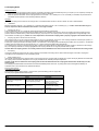
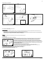
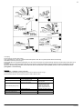
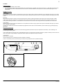
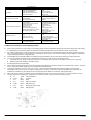
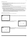
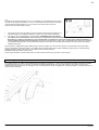
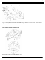
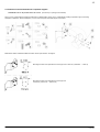
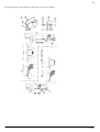
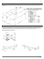
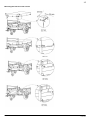
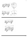
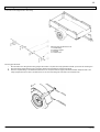
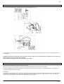
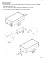
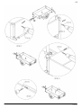
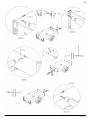
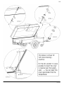
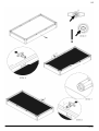
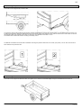
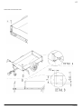
1
D
GB
Operating instructions
Caution: Before starting, please read and note the operating and safety instructions!
Operating and safety instructions for trailers:
Brand:
ANSSEMS
Type:
GT
Fabrikant – Hersteller – Manufacturer – Fabrikant:
ANSSEMS AANHANGWAGENS B.V.
www.anssems.eu
Versie: GT-2
2
Table of contents
Page
2
1. Introduction
2. Safety Precautions, Operation, Servecing and Cleaning (general)
2.1 Trailer (generel)
2.2 Coupling Head
2.3 Overrun Assembly (braked trailer)
2.4 Axle(s)
2.5 Electrical connection of the lighting system
2.6 Wheel and tyre
2.7 Jockey wheel
2.8 Opening/closing of the side boards
2.9 Charging of the trailer
2.10 Van Trailer / HT-and VT- versions
2
2
3
4
6
7
8
8
8
9
9
3. Mounting the mudgards
10
4. Mounting the wheel and tyre
4.1 For a central pole beam
4.2 For a V-pole beam
4.3 Fixation at the frontboard with separate support
11
11
11
12
5. Mounting the high cover
14
6. Mounting the flat cover
14
7. Mounting the ladderrack
17
8. Mounting the steel railing
18
9. Mounting the schockabsorbers (braked versions)
19
10. Mounting the hard top (opening at the side)
19
11. Mounting the protection sideways
26
12. Mounting the extension sides
25
13. Spare Parts
29
1 Introduction
Dear customer,
We congratulate you on purchasing a trailer with the brand Anssems. However, in the interests of safety, before using your trailer it is most important
that you familairize yourself with the operation of the trailer.
If there are any questions about the operation instructions please contact your dealer. Also for servecing and selling from accessories please contact
your dealer. For more information you can fill in the formulaire at our website www.anssems.eu
Please note
It is possible that the pictures in this operation instructions are not the same than the delivered trailer.
When we are talking about left, right, for and behind, we mean that you are standing behind the trailer.
2 Safety Precautions, Operation, Servecing and Cleaning (general)
2.1 Trailer (general)
•
•
•
•
•
•
No welding is permitted on the hot galvalised parts.
Other materials (like aluminium and cables) could be infuence, hereby there is a change on lasting damaging or remodelling.
There is a permit allowing the trailer to be used on roads in your country. This means that the vehicle has been formally offered to the inspection
authority in your country for approval when your trailer was manufactured in our factory. No modifications of any kind (for example different
lighting, wheel rims/tyres or coupling or the addition of an accessory not provided when the vehicle leaves our factory, and due to which the mass
and dimensions may change), may be made.
Maintenance and cleaning of hot-dip galvanised parts of the vehicle:
The formation of white rust is only a cosmetic fault. The following measures may be taken to avoid this to the extent possible:
•
Ensure that there is sufficient air circulation when parking and in connection with the storage of hot-dip galvanised components.
•
After driving in winter, the hot-dip galvanised surfaces may be cleaned with clean water in connection with salt/brine (for example using
steam jets).
For the safety instructions, operation, maintenance and cleaning of trailer component, please refer to items further discussed below, which apply
to your trailer.
Check whether driving with the trailer is officially allowed. Can the towing vehicle drive with the trailer, and does your driving licence permit you to
drive the combination?
Ensure conformity with the applicable laws relating to what the load may or may not consist of (such as hazardous substances and passengers).
Fabrikant – Hersteller – Manufacturer – Fabrikant:
ANSSEMS AANHANGWAGENS B.V.
www.anssems.eu
Versie: GT-2
3
2.2 Coupling Head
Safety Precautions:
•
Always ensure that the coupling head is properly connected to the towing vehiclis towball every time you couple up. If not coupled up correctly the
trailer may become detachted from the towing vehicle and cause an accident!
•
Maximum possible articulation of the coupling head must not exceed +/- 25° vertically and +/- 20° horizontally. If exceeded, components will be
overloaded and the operation of the assembly adversely affected.
Operation:
Operation of couplings of the brand AL-KO and type AK7 on unbraked trailers and AK75 / AK160 / AK300 / AK 350 on braked trailers:
•
Articulation:
Maintain articulation angle at +/- 25° (vertically Fig. 1) Maintain articulation angle at +/-20° horizontally (Fig. 1) Caution: If the articulation angle is
exceed, components will be overloaded. The function si no longer ensured!
•
Coupling Up ( AK 7):
Push the safety lever (afb. 4/1) up with the index finger and lift the handle up and forwards.
Put the openen coupling onto the towball with the handle pulled up and in addition press down by hand. The coupling will close by applying a light
pressure. Press the handle down by hand untill the catch (Fig. 4/3) snaps out. The coupling head is correctly engaged when the green edge of the
visual indicator is visible (Fig. 4/2) Caution: It is most important to check that the coupling head is properly engaged on the towball each time.
•
Coupling Up (AK75 / AK160 / AK 300 / AK 350):
Open coupling head. To do this pull the coupling handle up (Fig. 2/1) in the direction of the arrow. The coupling mechanism had fixed open position, i.e.
as long ad the coupling head is not placed on the ball the coupling handle will remain open.
Put the open coupling on the ball of the towing vehicle. The nose load on the coupling head automatically and audibly clics into position. In the interests
of safety press the handle down by hand as well (Fig. 2/1). Locking and securing takes place automatically.
The coupling ball is correctly connected when the green cylinder of the safety indicator is visible when the trailer coupling is viewed from the side (Fig.
2/2). The coupling mechanism is correctly engaged when the coupling handle can no longer be pressed down by hand.
Caution: When the coupling head is not correctly hitched onto the towball then the trailer can become disconnected from the towing vehicle.
•
Uncoupling:
Lift coupling handle fully and remove the coupling head from the towball of the towing vehicle. Where there are higher nose loads, coupling and
uncoupling can be made easier bu use of the jockey wheel.
•
Wear indicator (AK 7):
If the handle reaches back to the cutaway portion of the housing when the coupling head is engaged (Fig. 5) there wil be play between the towball and
the coupling head! Automatic readjustment is no longer possible and the assembly will require inspection.
Caution: Under these circumstances the coupling head can become detached from the coupling ball and the trailer break away from the
towing vehicle.
The coupling head and towball must therefore be checked immediately before future use. Any faulty patrs must be charnged immediately. All
mainenace work is to be carried out by specialist workshops.
Servicing and Cleaning:
Lubricationg points (Fig. 6)
Clean towball coupling. Lightly grease, or oil ball socket, jonts and bearing points as appropriate.
General purpose grease to DIN 51825 KTA 3K.
Troubleshooting
Fault
Cause
Coupling does not engage when
placed on ball.
Ball diameter grater than 50 mm.
Inner parts of the coupling are dirty
or are not funtioning correctly.
Elimination
Trailer cannot be uncoupled
Ball deformed.
Too much play in the coupling
danger of the trailer becomming
unhitched.
Coupling worn out.
Articulation angle exceeded. Rivet
bent.
Change ball
Clean and grease coupling,
replace as neccesarry.
Align trailer and car and
uncouple.
Grease/lubricate coupling
mechanism.
Have coupling changed.
Have towball changed.
Fabrikant – Hersteller – Manufacturer – Fabrikant:
ANSSEMS AANHANGWAGENS B.V.
www.anssems.eu
Versie: GT-2
4
Pictures chapter: 2.2 Coupplung
2.3 Overrun Assembly (braked trailer)
Safety Precautions:
•
When parking your vehicule and trailer on site you must applly the trailer parking brake. If the trailer is parked and then diconnected from the
towing vehicle it is recommended that each wheel is chocked using suitable wheel chocks.
Caution: Please note when parking the trailer that the wheelbrake auto-reverse mechanism will allow the trailer to travel backwards for
approximately 25 cm. (Please allow sufficient clearance when parking.)
Operation:
AL-KO overrun devices are of the mechanical overrun type using and hydraulic damper.
•
Coupling Up
Manoeuvre towing vehicle or trailer to couplingpoint.
Fully open coupling head handle and securely hitch onto the towball of the towing vehicle. -> See operating instructions for 50 mm coupling head.
Thread the breakaway cable through the breakaway cable guide provided (Fig. 2) and connect it to
attachment point provided on towing brecket (Fig. 1). Only for Scandinavian countries (see fig 1a).
The breakaway cable operates the hand-brake (emergency brake) in the event of the trailer becoming
detached from the towing vehicle during towing. For this emergency brake to work correctly it is absolutely
necessary that the breakaway cable runs through the breakaway cable guide and is not resticted in any way
Caution: The Brake-away cable must be of sufficient length to avoid applying the emergency brake
in advertently when conering.
Overrun device fitted with 50 mm coupling head/ eye end
Connect trailer electric plug controlling lights & indicators etc. to towing vehicle socket.
Wind the jockey wheel up fully clamp securely in position ensuring that it does not foul brake rod or
breakaway cable. (See operating instructions for jockey wheel.)
Ensure handbrake is in the fully of position by pushing it right down. (See Figures 3-6)
Caution Failure to comply with this could result in the brakes overheating!
For details on the hand-brake see section on Uncoupling.
Remove wheel shocks and store or stow safely.
Fabrikant – Hersteller – Manufacturer – Fabrikant:
ANSSEMS AANHANGWAGENS B.V.
www.anssems.eu
Versie: GT-2
5
Uncoupling
Secure trailer by chocking both wheels.
Apply hand-brake fully. There are 4 different hand-brake systems. With all four systems please observe the following:
Hand-Brake lever with gas strut (Fig 3)
Enure handbrake is fully applied (as highlighted). This will ensure that the gas strut will automatically reapply the wheel brakes if trailer starts to roll
backwards.
To release: Press the hand-brake push button fully home and firmly press the handbrake lever back into the off position (handbrake horizontal)
Attention: Do not put any presssure on the brake rod when the hand brake is opend (OPEN) because in this case hand brake or the
parkingbrake is not functioning.
Servicing:
Every 10 000 – 15 000 km or every 12 months:
Lubricate/grease all sliding and moving parts of the overrun device as shown in Fig. 7.
Recommended lubricant: General purpose grease to DIN 51825 KTA 3KA
Troubleshooting
Fault
Poor Breking
Cause
Elimination
Overrun shaft/linkages tight
Overrun shaft corroded
Damage to body housing
Hand-brake not fully released
Wheel fouls brake rod
Gas strut defective
Axle shock absorbers defective
Release hand-brake
Check transmission system
operates smoothly. Check
overrun lever moves freely
Slacken locking handle and
repossition accembly correctly
Replace gas strut
Replace schock absorbers
Overrun damper defective
Replace overrun damper
Brake overheating during towing
Handbrake force low
Uncomfortable ride
Trailer brakes applied during
decleration or downhill travel
Grease transmission system and
all moving parts
Fabrikant – Hersteller – Manufacturer – Fabrikant:
ANSSEMS AANHANGWAGENS B.V.
www.anssems.eu
Versie: GT-2
6
2.4 Axle
Safety Precautions:
•
No welding is permitted on AL-KO axles.
•
It is most important that the wheel and hub/brake drum are dimensionally compatible. This means that the P.C.D., wheel bolts and inset must all
be compatible with both the hub/brake drum and the wheel rim. Particular attention must be paid to the recommended torque figures for the
wheels bolts.
Operation Instructions:
Function:
Service brake:
When the towing vehicle is braking or travelling down hill the overrun device shaft is pushed in (dependent on the magnitude of the thrust on the shaft)
and presses on the overrun lever. This acts on the bowden cables an expander mechanism which in turn expands the brake shoes applying the wheel
brakes.
Reversing:
When the towing vehicle is reversing, the overrun device shaft is pushed in, applying the brakes via the overrun lever, brake rod system, bowden
cables and the expander mechanism. The backwards rotation of the brake drum causes the secondary brake shoe to collapse cancelling out the
braking effect allowing the trailer to move backwards. At the same time the transmission lever swings back and compensates for the entire travel
Parking Brake:
With the gas strut version pull the hand-brake lever over top dead centre. With the spring cylinder version pull the hand-brake lever right up to the last
tooth. The trailer is then braked.
Important note: Please note that with the handbrake fully applied the trailer is able to move backwards by 25cms until the spring cylinder/gas spring
takes effect.
Maintenance and cleaning:
Braked axle:
The axels comes fitted with maintenance tree wheel bearings (greased and seled for life) and no adjustment is necessary. The hub bearing is not
protected against water ingress.
Check wheel brake linings for wear every 10 000 kilometres or every 12 months via the inspection hole (Fig.2/1) Adjust if necessary. Where continuous
travel in hilly regions or high mileage is experienced earlier inspection and adjustment may be necessary.
Unbraked axle:
After 1500 km or 6 months;
Have the axial play of the hub bearing checked an adjusted, if necessary.
Caution: All necessary service work should only be carried out by trained personnel in specialist workshops
Fabrikant – Hersteller – Manufacturer – Fabrikant:
ANSSEMS AANHANGWAGENS B.V.
www.anssems.eu
Versie: GT-2
7
Troubleshooting
Fault
Cause
Elimination
Poor braking
Linings are not fully bedded in.
Linings are damaged/dirty
Friction losses too high, overrun
device shaft corroded.
Reversing heavy or blocked
Only occurs when the braking system
is set too thightly.
Auto-reverse lever is stuck.
Brakes overheating when driving
Incorrect setting.
Braking system not fully released
during forward travel.
Overrun lever stuck
Wheel brake dirty.
Cable or Bowden cable kinked.
Release springs defective or broken.
Rust deposit in brake drum(s)
Handbrake force low
Incorrect setting – friction losses too
great.
Linings are not run in.
Friction losses too high.
Uncomfortable ride or jerky
braking
Too much play in the braiking system.
Shock absorber defective.
Will pass after braking a few
times.
Have set replaced.
Ensure smooth action of
transmossion
Equipment including brake cable.
Re-adjust braking system.
Restore to working order and
lubricate.
Check brake adjustment.
Release hand-brake. Check
transmission equipment (ensure
smooth action).
Check overrun lever.
Clean.
Renew Bowden cable.
Renew springs.
Replace brake drum(s) and
shoes, if necessary.
Check stting.
Will pass after braking a few
times.
Ensure smooth action of
transmission equipment including
Bowden cable. (Oil)
Check setting.
Have shock absorber checked
and if necessary change.
2.5 Electrical connection of the lighting system
•
When coupling the trailer, the proper working of the lighting system should be checked after inserting the plug into the vehicle plug. If the working
is not satisfactory, the cause of the problem should first be identified and repaired before the combination is driven on public roads.
•
Your trailer is equipped with a 7-pole plug as per ISO 1724. If the towing vehicle is not equipped with a plug socket of this type (but is equipped
with a 13-pole plug as per ISO 11446 for example), the lighting will not work properly. This can be remedied by using an adapter for connecting a
13-pole vehicle plug socket to a 7-pole trailer plug.
•
•
These adapters are commercially available. This adapter will be placed between the plug of the towing vehicle and the plug of the trailer.
You may check whether the towing vehicle is equipped with the same type (7-pole) of plug in the following manner:
•
If the words “ISO 1724” appear on the plug, it means it is a 7-pole plug; if the words “ISO 11446“ appear, it means it is a 13-pole plug.
•
•
Please enquire with the supplier of the towing vehicle.
No extra lighting fixtures need be added.
•
When replacing (incandescent) lamps, it should be ensured that the replacement (incandescent) lamp is in accordance with (12V/5W – 12V/21W).
For this, check the information appearing on the replacement (incandescent) lamp.
•
The trailer is permitted for use on the road in your country. This means that the vehicle has been offered for inspection to the authority
responsible for the same, as soon as your trailer is manufactured in our factory, and therefore fulfils the applicable permit requirements. No
modifications or additions may be made to the same (extra lighting and the addition of for example, "lighting safety grills").
•
After coupling, the 7-pole plug of the trailer should be immediately inserted in the plug of the towing vehicle. This is only possible in one way.
The plug connection is as follows (with, in sequence, the connection number / code, colour of the wiring and function):
•
•
•
•
•
•
1/L
Yellow
Left turn indicator
2 / 54G
3 / 31
Blue
White
Fog lamp
Earth
4/R
Green
Right turn indicator
•
5 / 58R
6 / 54
Brown
Red
Rear lamp, right
Braking light, left and right
•
7 / 58L
Black
Rear lamp, left
Fabrikant – Hersteller – Manufacturer – Fabrikant:
ANSSEMS AANHANGWAGENS B.V.
www.anssems.eu
Versie: GT-2
8
2.6 Wheel & Tyre
•
Ensure that the tyres are at the correct tyre pressure and have an adequate tyre tread (as regards safety and uniformity of wear-and-tear). The
tyre pressure should be applied in the "cold" condition with the vehicle in an unloaded condition.
Tyre
Tyre Pressure
[bar]
175/70 R13
185/70 R13
145 R13
145/80 R13
155 R13
155/80 R13
2.5
2.5
ATTENTION: You cannot ensure that your tyres have a minimum pressure of 6.25 bars in all places. If tyres have a tyre pressure less the values
mentioned in the table, there is a chance of punctures. The tyre pressure should be checked regularly.
For information about the minimum tyre tread, please abide by the applicable regulations.
•
The following applies to a new trailer: After 50 km, tension the wheel nuts with a suitable tool. This should be done with a tightening
torque of 90-120 Nm.
If a trailer is regularly used, it should also be regularly checked later on.
2.7 Jockey Wheel
•
•
•
•
•
•
•
•
•
•
•
•
•
The jockey wheel is for coupling, uncoupling and shunting of the trailer.
Ensure that the maximum permissible coupling pressure is not exceeded through the loading of the trailer. At this load, where the jockey
wheel is used, a permissible load of the jockey wheel will arise.
Operation of the jockey wheel, Version 1 (unbraked trailer)
Uncoupling of unbraked trailer:
Open the jockey wheel holder by releasing the clamping handle (1), lower the jockey wheel as far as possible and tighten the
clamping handle (1) again.
Uncouple the auxiliary coupling and the lighting plug from the towing vehicle. Use the wheel stops for the unbraked trailer.
Open the coupling head, and simultaneously turn out the jockey wheel by turning the handle (2) to the left, until the coupling
of the towing hook ball is detached from the towing vehicle.
Coupling of unbraked trailer:
The coupling must be done in reverse order:
Turn up the jockey wheel until the wheel flanges are fixed in the recess of the outer tube (3). The clamping handle (1)
must be firmly tightened.
The jockey wheel is thereby secure against accidental detachment during motion.
The jockey wheel should be pulled-up to the maximum possible extent using the clamping bracket. While doing this, the
wheel should be more or less parallel to the pole.
2.8 Opening and closing of the side boards
•
When opening and closing the side boards, ensure that persons present near the boards are not exposed to danger, or risk getting entrapped, or
injured in any other manner whatsoever.
While opening the tailboards on public roads, the applicable laws should be duly followed. If the applicable laws require this, use the pull-out
beams present in the trailer. When the tailboard is resting on the pull-out beams, the lighting fittings remain visible. The lock for the pull-out beam
is placed behind the lighting box. The pull-out beam is unlocked on pulling down the lock, and can be pushed out backwards. The tailboard can
thereby be laid horizontally on the pull-out beams. The lighting and reflectors will therefore remain visible during loading and unloading.
ATTENTION: Ensure that you are visible during loading/unloading on public roads. This is for your safety and that of other road users.
NEVER ride with the opened sides.
•
Ensure regular lubrication of the lock mechanism. This can be done from the top using a Teflon or silicone spray.
•
•
Fabrikant – Hersteller – Manufacturer – Fabrikant:
ANSSEMS AANHANGWAGENS B.V.
www.anssems.eu
Versie: GT-2
9
2.9 Charging of the trailer
•
•
•
•
•
•
The cargo should be properly secured in place. This is to prevent loss and shifting of the cargo during motion. The shifting of the cargo may lead
to a sudden change in the handling characteristics of the vehicles.
Furthermore, while loading the vehicle on public roads, follow all the applicable regulations (among others, the visibility of the lighting and
maximum length of projecting cargo).
Check whether it is permissible to drive with the trailer.
•
Does the towing vehicle allow driving with the trailer?
•
Is the combination in accordance with your Driving Licence?
It is preferable to load and unload your trailer in the coupled condition. If this is not done, check whether the trailer may "topple" (the jockey wheel
lifts off the ground) during loading or unloading.
Follow the applicable laws concerning what the load may consist of (such as hazardous substances and persons).
While loading the trailer, keep in mind the net loading capacity of the axle(s) and the coupling. Distribute the loading in such a manner over the
loading floor that the correct coupling pressure is achieved. This coupling pressure should never exceed the maximum permissible level, and
should also be in accordance with the possible coupling pressure for the towing vehicle. For the correct information, please contact your (towing)
vehicle supplier, or check the user manual of the towing vehicle.
•
ATTENTION: The coupling pressure should never be negative (this would mean that the coupling is pulling vertically on the towing
hook ball of the towing vehicle). For the minimum coupling pressure, duly follow the applicable laws and regulations.
•
ATTENTION: Your trailer is designed, calculated and tested (through a life test) for the loads as mentioned in the documents
relating to your trailer, and for the maximum speed applicable on public roads for a towing vehicle with trailer. The permissible
loads may be found on the construction plate (or the type plate) installed on the trailer. Overloading may lead to permanent
damage to some components. We accept no liability for the same as manufacturers.
2.10 Van Trailer / HT- en VT-versions
We can deliver the GT-trailer also as a van trailer. Below you can see the different versions.
HT:
The standard trailer is equipped with a hard top which opens at the frontside. The internal hight is
now 48 cm. The hard top can remain open with a shock absorber.You can load the trailer very easy.
VT1:
The hight of the side and frontboard is 65 cm. The tailboard is similar to the tailboard of the
standard open version. A remouvable tailboard is extra. The internal hight is now 83 cm. The hard
top can remain open with a shock absorber.You can load the trailer very easy
VT2:
The hight of the side and frontboard is 100 cm. The tailboard is one complete board which opens
from below. The length of this board is ca. 100 cm. In combination with the hard top which opens at
the frontside the internal hight is 118 cm. The hard top can remain open with a shock absorber.You
can load the trailer very easy
Fabrikant – Hersteller – Manufacturer – Fabrikant:
ANSSEMS AANHANGWAGENS B.V.
www.anssems.eu
Versie: GT-2
10
VT3:
The hight of the side and frontboard is 135 cm. The tailboard is one complete board which opens
from below. The length of this board is ca. 135 cm. In combination with the hard top which opens
at the frontside the internal hight is 153 cm. The hard top can remain open with a shock
absorber.You can load the trailer very easy
•
When opening and closing the boards, ensure that persons present near the boards are not
exposed to danger, or risk getting entrapped, or injured in any other manner whatsoever.
•
The hard top cover is equipped with a shock absorber. ATTENTION: By the mechanicem
the hard top cover must be pulled “over the zero point”. The pressure of the shock absorber is determed by a “empty” hard cover.
When there is a loading on the hard cover, the shock absorber can function less. (hard cover remains open) The shock absorber in a
closed condition gives also more closing power. While opening the tailboards on public roads, the applicable laws should be duly followed. If
the applicable laws require this, use the pull-out beams present in the trailer. When the tailboard is resting on the pull-out beams, the lighting
fittings remain visible.
When the trailer is equipped with dismountable hinge pins below the tailgate, you can move the hinge pins to the side after removing the hairpin
springs. The tailgate is now dismountable. In this situation also the lighting fittings remain visible. ATTENTION: Ensure that you are visible during
loading/unloading on public roads. This is for your safety and that of other road users.
NEVER drive with the boards or hard top open
Ensure regular lubrication of the lock mechanism. This can be done from the top using a Teflon or silicone spray.
3. Mounting the mudgards
For logistique raisons your trailer is being deliverd without mudgards from the factory. In many cases your dealer has already mounted the mudgards
as descriped below. When not you can do it yourself with the fixationmaterials before you go into public roads with your trailer. The holes in the
sideboard are already there so it is not necessary to bore. The example below shows a mudgards from a single axle trailer. For a double axle you can
follow the same instructions.
Fabrikant – Hersteller – Manufacturer – Fabrikant:
ANSSEMS AANHANGWAGENS B.V.
www.anssems.eu
Versie: GT-2
11
4. Mounting the wheel and tyre
4.1 For a central drawbar (platform width 101 cm)
Your trailer can be equipped with a spare wheel. The cental profile is already prepared for this. When this is not the case, your dealer can do it for you.
You can can mount the wheel with the fixationmaterial with the outside of the rim up. With the bolts you can fasten the wheel. The parts needed are
being deliverd with the spare wheel. Please follow the instructions on the drawing at the side.
Detail for the fixation for trailers with a central drawbar. (platform width 101 cm).
4.2 For a drawbar V (platform width 126/151 cm)
.
Detail for the fixation for trailers with a V drawbar. (platform width 126 cm)
Fabrikant – Hersteller – Manufacturer – Fabrikant:
ANSSEMS AANHANGWAGENS B.V.
www.anssems.eu
Versie: GT-2
12
4.3 Fixation on the frontboard with a separate support
ATTENTION: This is not possible with a HT version. (The hard top is opening at the frontside)
When you buy a spare wheel and support a description is delivered also. When you buy a sparewheel including a separate support a mounting
description is attached. With this description you can mount the spare wheel and support on the trailer.
Materials for fixation needed and detail for fixation off the spare wheel on the support.
Mounting the bolts of the spare wheel on the support for 4-holes rim (145/80 R13 / 145 R13)
Mounting the bolts of the spare wheel on the support for
5-holes rim (175/70 R13 / 185/70 R13)
Fabrikant – Hersteller – Manufacturer – Fabrikant:
ANSSEMS AANHANGWAGENS B.V.
www.anssems.eu
Versie: GT-2
13
Mounting the support on the frontboard. The place where you must bore is indicated.
Fabrikant – Hersteller – Manufacturer – Fabrikant:
ANSSEMS AANHANGWAGENS B.V.
www.anssems.eu
Versie: GT-2
14
5. Mounting the High Cover
When you buy a high cover a description is deliverd also. With this description you can mount the high cover.One dimension is shown. Different sizes
are possible.
Opgave van de meeverpakte onderdelen:
Opgave van de hoofdonderdelen:
6. Mounting the flatcover
Your trailer can be equipped with a flatcover. You can mount the flatcover on the following way. See drawings below. It is depending from the length
and the width of the trailer if there must be fixed extra straps at the sideboards or at the front- or tailgate of the trailer. To determine the precise spot for
the straps you first must fit the flatcover over the trailer. After boring the holes you can mount the flatcover with the rivets. See below.
Mounting the flatcover (old version)
Fabrikant – Hersteller – Manufacturer – Fabrikant:
ANSSEMS AANHANGWAGENS B.V.
www.anssems.eu
Versie: GT-2
15
Mounting the flatcover new version
Fabrikant – Hersteller – Manufacturer – Fabrikant:
ANSSEMS AANHANGWAGENS B.V.
www.anssems.eu
Versie: GT-2
16
Fabrikant – Hersteller – Manufacturer – Fabrikant:
ANSSEMS AANHANGWAGENS B.V.
www.anssems.eu
Versie: GT-2
17
7. Mounting the ladderrack
Your trailer can be equipped with a ladderrack.
Remove the plastic caps in the corners.
You can bore the holes in the left and right corner like described below.
1 x Left and 1 x Right.
Mounting the ladderrack like described below.
Fabrikant – Hersteller – Manufacturer – Fabrikant:
ANSSEMS AANHANGWAGENS B.V.
www.anssems.eu
Versie: GT-2
18
8. Mounting the steel railing
Your trailer can be equipped with a steel railing.
Following parts are deliverd in a set.
1. 2x Profile railing
2. 8x Railing uprights
3. 32x Rivets
4. 4x Plastic caps
Mounting goes as follows:
1.
2.
3.
Bore the holes in the railing and the railing uprights with ø6.5mm. The parts are hot dip galvinized. Herewith you remove the remaining zinc.
Mount the railing uprights with the rivets to the railing. Please note that these are mounted at 90 degres.
Place the complete railing on the sideboard between the front cornerpièce and the upright profile at the backside. Adapt the holes of the
railing uprights and bore the holes in the side board. You can mount the railing with rivets and mount the plastic caps.
Fabrikant – Hersteller – Manufacturer – Fabrikant:
ANSSEMS AANHANGWAGENS B.V.
www.anssems.eu
Versie: GT-2
19
9. Mounting the shock absorber (Braked version)
Your trailer can be equipped with shock absorbers. (only possible for the braked trailers)
From the first axle hole the distance between the holes must be drilled at ø11mm. Please follow the pictures for mounting the shock absorber and the
mounting plate.
ATTENTION: Bolt heads should always point in the direction of the tyre and the axle shock absorber will be installed on the "inner side" only
with the 750 kg types. Please check the previous pages
After installation, check that the tyres have sufficient play (min. 16 mm).
10. Mounting the hard top (opening at the side)
Your trailer can be equipped with a hard top with aluminium railing.
When you buy a hard top a fitting description is attached. With this description the hard top can be fitted on the trailer.
The opening side indicated in the manual is based on opening the hard top to pavement side. When you change the assembly / drilling images the
opening side at the other side can be chosen.
ATTENTION:
The hard top cover is equipped with a shock absorber. By the mechanicem the hard top cover must be pulled “over the zero point”. The pressure of the
shock absorber is determed by a “empty” hard cover. When there is a loading on the hard cover, the shock absorber can function less. (hard cover
remains open) The shock absorber in a closed condition gives also more closing power.
Fabrikant – Hersteller – Manufacturer – Fabrikant:
ANSSEMS AANHANGWAGENS B.V.
www.anssems.eu
Versie: GT-2
20
Opening and closing the hard top
While opening and closing the hard top ensure that persons present near the boards are not exposed to danger, or risk getting entrapped, or injured in
any other manner whatsoever.
•
•
•
•
While opening the tailgate on public roads, the applicable laws should be duly followed (only possible with an open hard top) ATTENTION:
Ensure that you are visible during loading/unloading on public roads. This is for your safety and that of other road users.
NEVER drive with a hard top which is open.
Ensure regular lubrication of the lock mechanism. This can be done from the top using a Teflon or silicone spray.
You can load on the hard top till 100 kg equelly. Ensure that the load is properly fastend on the hard top.
ATTENTION: When there is a loading on the hard cover, the shock absorber can function less.
Fabrikant – Hersteller – Manufacturer – Fabrikant:
ANSSEMS AANHANGWAGENS B.V.
www.anssems.eu
Versie: GT-2
21
Fabrikant – Hersteller – Manufacturer – Fabrikant:
ANSSEMS AANHANGWAGENS B.V.
www.anssems.eu
Versie: GT-2
22
Fabrikant – Hersteller – Manufacturer – Fabrikant:
ANSSEMS AANHANGWAGENS B.V.
www.anssems.eu
Versie: GT-2
23
Fabrikant – Hersteller – Manufacturer – Fabrikant:
ANSSEMS AANHANGWAGENS B.V.
www.anssems.eu
Versie: GT-2
24
Fabrikant – Hersteller – Manufacturer – Fabrikant:
ANSSEMS AANHANGWAGENS B.V.
www.anssems.eu
Versie: GT-2
25
Fabrikant – Hersteller – Manufacturer – Fabrikant:
ANSSEMS AANHANGWAGENS B.V.
www.anssems.eu
Versie: GT-2
26
11. Mounting the protection sides
Your trailer can be equipped with protection sides.
The protection sides are being deliverd with all fixation material needed. Before mounting the protection sides you must determine the right place. This
is against the vertical strip below the sideboard and also you should be aware off an distance of max. 300 mm from the front of the wheel. You can use
the protection sides as an example for the holes you must bore. The diameter for the holes is 11 mm.
The chassis beam contains the holes for the fixing of the safety covers.
ATTENTION: the reflektor which becomes invisible after mounting the protection sides has to be moved. (see picture). You can also chose to fixe an
extra reflector at the protection side.
12. Mounting the extension sides
Your trailer can be equiped with extension sides. The hight is 35 cm. With the remountable tailgate the hight of the sideboard becomes 65 cm.
Fabrikant – Hersteller – Manufacturer – Fabrikant:
ANSSEMS AANHANGWAGENS B.V.
www.anssems.eu
Versie: GT-2
27
Please follow the instructions below.
Fabrikant – Hersteller – Manufacturer – Fabrikant:
ANSSEMS AANHANGWAGENS B.V.
www.anssems.eu
Versie: GT-2
28
Fabrikant – Hersteller – Manufacturer – Fabrikant:
ANSSEMS AANHANGWAGENS B.V.
www.anssems.eu
Versie: GT-2
29
13. Spare Parts
Spare parts are very important for the safety of the trailer. When you do not use original spare parts, we are not longer responsible for the product and
if other than the original spare parts are being used, then the warranty and product liability expires. Meaning that we as a manufacturer no longer
responsible for any errors occurring or the consequences. Consequential damages and injuries on public roads may not be underestimated, keep this
in mind when using spare parts!
Fabrikant – Hersteller – Manufacturer – Fabrikant:
ANSSEMS AANHANGWAGENS B.V.
www.anssems.eu
Versie: GT-2