1
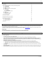
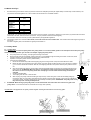
1
GB
Operating instructions
Caution: Before starting, please read and note the operating and safety instructions!
Operating and safety instructions for trailers:
Brand:
ANSSEMS
Type:
AMT
Fabrikant – Hersteller – Manufacturer – Fabrikant:
ANSSEMS AANHANGWAGENS B.V.
www.anssems.eu
Versie: AMT-1
2
Table of contents
Pagina
2
1. Introduction
2. Safety Precautions, Operation, Servecing and Cleaning (general)
2.1 Trailer (generel)
2.2 Coupling Head
2.3 Overrun Assembly
2.4 Axles
2.5 Electrical connection of the lighting system
2.6 Wheel and tyre
2.7 Jockey Wheel
2.7.1 Jockey Wheel
2.7.2 Tipping the jockey wheel
2.8 Winch
2.9 Wheel wedge
2.10 Ramps (i.c.m. supports)
2.11 Charging the trailer
2
2
3
4
6
7
8
8
8
9
10
11
11
14
3. Mounting the mudgards
14
4. Mounting the Wheel and Tyre (option)
15
5. Mounting the shock absorber (option)
17
6. Using accessoiries (option):
6.1 Front and Tailgate (option)
6.2 Wheel stop (option)
18
18
19
7. Spare parts
19
1 Introduction
Dear customer,
We congratulate you on purchasing a trailer with the brand Anssems. However, in the interests of safety, before using your trailer it is most important
that you familairize yourself with the operation of the trailer.
If there are any questions about the operation instructions please contact your dealer. Also for servecing and selling from accessories please contact
your dealer. For more information you can fill in the informationformulaire at our website. www.anssems.eu
Please note
It is possible that the pictures in this operation instructions are not the same than the delivered trailer.
When we are talking about left, right, for and behind, we mean that you are standing behind the trailer.
2 Safety Precautions, Operation, Servicing and Cleaning (general)
2.1 Trailer (general)
•
•
•
•
•
•
No welding is permitted on the hot galvalised parts.
Other materials (like aluminium and cables) could be infuence, hereby there is a change on lasting damaging or remodelling.
There is a permit allowing the trailer to be used on roads in your country. This means that the vehicle has been formally offered to the inspection
authority in your country for approval when your trailer was manufactured in our factory. No modifications of any kind (for example different
lighting, wheel rims/tyres or coupling or the addition of an accessory not provided when the vehicle leaves our factory, and due to which the mass
and dimensions may change), may be made.
Maintenance and cleaning of hot-dip galvanised parts of the vehicle:
The formation of white rust is only a cosmetic fault. The following measures may be taken to avoid this to the extent possible:
•
Ensure that there is sufficient air circulation when parking and in connection with the storage of hot-dip galvanised components.
•
After driving in winter, the hot-dip galvanised surfaces may be cleaned with clean water in connection with salt/brine (for example using
steam jets).
For the safety instructions, operation, maintenance and cleaning of trailer component, please refer to items further discussed below, which apply
to your trailer.
Check whether driving with the trailer is officially allowed. Can the towing vehicle drive with the trailer, and does your driving licence permit you to
drive the combination?
Ensure conformity with the applicable laws relating to what the load may or may not consist of (such as hazardous substances and passengers).
Fabrikant – Hersteller – Manufacturer – Fabrikant:
ANSSEMS AANHANGWAGENS B.V.
www.anssems.eu
Versie: AMT-1
3
2.2 Coupling Head
Safety Precautions:
•
Always ensure that the coupling head is properly connected to the towing vehiclis towball every time you couple up. If not coupled up correctly the
trailer may become detachted from the towing vehicle and cause an accident!
•
Maximum possible articulation of the coupling head must not exceed +/- 25° vertically and +/- 20° horizontally. If exceeded, components will be
overloaded and the operation of the assembly adversely affected.
Operation
•
Articulation:
Maintain articulation angle at +/- 25° (vertically Fig. 1) Maintain articulation angle at +/-20° horizontally (Fig. 1) Caution: If the articulation angle is
exceed, components will be overloaded. The function is no longer ensured!
•
Coupling Up:
Open coupling head. To do this pull the coupling handle up (Fig. 2/1) in the direction of the arrow. The coupling mechanism had fixed open position, i.e.
as long ad the coupling head is not placed on the ball the coupling handle will remain open.
Put the open coupling on the ball of the towing vehicle. The nose load on the coupling head automatically and audibly clics into position. In the interests
of safety press the handle down by hand as well (Fig. 2/1). Locking and securing takes place automatically.
The coupling ball is correctly connected when the green cylinder of the safety indicator is visible when the trailer coupling is viewed from the side (Fig.
2/2). The coupling mechanism is correctly engaged when the coupling handle can no longer be pressed down by hand.
Caution: When the coupling head is not correctly hitched onto the towball then the trailer can become disconnected from the towing vehicle.
•
Uncoupling:
Lift coupling handle fully and remove the coupling head from the towball of the towing vehicle. Where there are higher nose loads, coupling and
uncoupling can be made easier bu use of the jockey wheel.
•
Wear indicator:
A wear indicator on the coupling head (Fig. 3) shows whether the wear limit of the towing vehicle’s towball or the trailing coupling has been reached or
not. For this purpose hitch up the trailer to the towing vehicle (see Coupling Up) and drive the car and trailer approx. 500m. This will set the coupling
head adjustment. Following this check wear as follows: If the green indicator is visible on the coupling head with the coupling engaged (see Fig. 3/2)
the coupling head is in a new condition or the wear on the towball is within permissible limits.
When the green indicator on the coupling handle is completely covered over and only the red indicator visible (Fig. 3/1) this could be caused by the
following:
•
The towball has reached the lowest wear limit of dia. 49
•
Both coupling head and the towball are showing sings of wear
•
Towball is in a new condition with dia. 50 but the coupling head is showing an excessive level of wear
Caution: Under these cicumstances the coupling head can become detached from the coupling ball and the trailer break away from the
towing vehicle! The coupling head and towball must therefore be checked immediately befor future use! Any fauly parts must be changed
immediately! All maintenace word must be carried out by specialist workshops.
Servicing and Cleaning:
Clean towball coupling. Lightly grease, or oil ball socket, jonts and bearing points as appropriate.
General purpose grease to DIN 51825
Troubleshooting
Fault
Cause
Coupling does not engage when
placed on ball.
Ball diameter grater than 50 mm.
Inner parts of the coupling are dirty
or are not funtioning correctly.
Solution
Trailer cannot be uncoupled
Ball deformed.
Too much play in the coupling
danger of the trailer becomming
unhitched.
Coupling worn out.
Articulation angle exceeded. Rivet
bent.
Change ball
Clean and grease coupling,
replace as neccesarry.
Align trailer and car and
uncouple.
Grease/lubricate coupling
mechanism.
Have coupling changed.
Have towball changed.
Fabrikant – Hersteller – Manufacturer – Fabrikant:
ANSSEMS AANHANGWAGENS B.V.
www.anssems.eu
Versie: AMT-1
4
Pictures paragraphe: 2.2 Coupling
2.3 Overrun Assembly
Safety Precautions:
•
When parking your vehicule and trailer on site you must applly the trailer parking brake. If the trailer is parked and then diconnected from the
towing vehicle it is recommended that each wheel is chocked using suitable wheel chocks.
Caution: Please note when parking the trailer that the wheelbrake auto-reverse mechanism will allow the trailer to travel backwards for
approximately 25 cm. (Please allow sufficient clearance when parking.)
Operation:
AL-KO overrun devices are of the mechanical overrun type using and hydraulic damper.
•
Coupling Up
Manoeuvre towing vehicle or trailer to couplingpoint.
Fully open coupling head handle and securely hitch onto the towball of the towing vehicle. -> See operating instructions for 50 mm coupling head.
Thread the breakaway cable through the breakaway cable guide provided (Fig. 2) and connect it to attachment point provided on towing brecket (Fig.
1). Only for Scandinavian countries (see fig 1a).
The breakaway cable operates the hand-brake (emergency brake) in the event of the trailer becoming detached from the towing vehicle during
towing. For this emergency brake to work correctly it is absolutely necessary that the breakaway cable runs through the breakaway cable guide
and is not resticted in any way
Caution: The Brake-away cable must be of sufficient length to avoid applying the emergency brake in advertently when conering.
Overrun device fitted with 50 mm coupling head/ eye end
Connect trailer electric plug controlling lights & indicators etc. to towing vehicle socket.
Wind the jockey wheel up fully clamp securely in position ensuring that it does not foul brake rod or breakaway cable. (See operating instructions for
jockey wheel.)
Ensure handbrake is in the fully of position by pushing it right down. (See Figures 3-6)
Caution Failure to comply with this could result in the brakes overheating!
For details on the hand-brake see section on Uncoupling.
Remove wheel shocks and store or stow safely.
Fabrikant – Hersteller – Manufacturer – Fabrikant:
ANSSEMS AANHANGWAGENS B.V.
www.anssems.eu
Versie: AMT-1
5
•
Uncoupling
Secure trailer by chocking both wheels.
Apply hand-brake fully. There are 4 different hand-brake systems. With all four systems please observe the following:
Hand-Brake lever with gas strut (Fig 3)
Enure handbrake is fully applied (as highlighted). This will ensure that the gas strut will automatically reapply the wheel brakes if trailer starts to roll
backwards.
To release: Press the hand-brake push button fully home and firmly press the handbrake lever back into the off position (handbrake horizontal)
ATTENTION: The brake rod can not be in open position from the handbrake lever, because in that case the brake or parkingbrake does not
function.
Servicing:
Every 10 000 – 15 000 km or every 12 months:
Clean towball coupling. Lightly grease, or oil ball socket, jonts and bearing points as appropriate.
General purpose grease to DIN 51825
Troubleshooting
Default
Poor Breking
Cause
Solution
Overrun shaft/linkages tight
Overrun shaft corroded
Damage to body housing
Hand-brake not fully released
Wheel fouls brake rod
Gas strut defective
Axle shock absorbers defective
Release hand-brake
Check transmission system
operates smoothly. Check
overrun lever moves freely
Slacken locking handle and
repossition accembly correctly
Replace gas strut
Replace schock absorbers
Ovverrun damper defective
Replace overrun damper
Brake overheating during towing
Handbrake force low
Uncomfortable ride
Trailer brakes applied during
decleration or downhill travel
Grease transmission system and
all moving parts
Fabrikant – Hersteller – Manufacturer – Fabrikant:
ANSSEMS AANHANGWAGENS B.V.
www.anssems.eu
Versie: AMT-1
6
2.4 Axles
Safety Precautions:
•
No welding is permitted on AL-KO axles.
•
It is most important that the wheel and hub/brake drum are dimensionally compatible. This means that the P.C.D., wheel bolts and inset must all
be compatible with both the hub/brake drum and the wheel rim. Particular attention must be paid to the recommended torque figures for the
wheels bolts.
Operation Instructions:
Function:
Service brake:
When the towing vehicle is braking or travelling down hill the overrun device shaft is pushed in (dependent on the magnitude of the thrust on the shaft)
and presses on the overrun lever. This acts on the bowden cables an expander mechanism which in turn expands the brake shoes applying the wheel
brakes.
Reversing:
When the towing vehicle is reversing, the overrun device shaft is pushed in, applying the brakes via the overrun lever, brake rod system, bowden
cables and the expander mechanism. The backwards rotation of the brake drum causes the secondary brake shoe to collapse cancelling out the
braking effect allowing the trailer to move backwards. At the same time the transmission lever swings back and compensates for the entire travel
Parking Brake:
With the gas strut version pull the hand-brake lever over top dead centre. With the spring cylinder version pull the hand-brake lever right up to the last
tooth. The trailer is then braked.
Important note: Please note that with the handbrake fully applied the trailer is able to move backwards by 25cms until the spring cylinder/gas spring
takes effect.
Maintenance and cleaning:
The axels comes fitted with maintenance tree wheel bearings (greased and seled for life) and no adjustment is necessary. Attention: The hub bearing is
not protected against water ingress.
Check wheel brake linings for wear every 10 000 kilometres or every 12 months via the inspection hole (Fig.2/1) Adjust if necessary. Where continuous
travel in hilly regions or high mileage is experienced earlier inspection and adjustment may be necessary.
Caution: All necessary service work should only be carried out by trained personnel in specialist workshops.
Fabrikant – Hersteller – Manufacturer – Fabrikant:
ANSSEMS AANHANGWAGENS B.V.
www.anssems.eu
Versie: AMT-1
7
Troubleshooting
Default
Cause
Solution
Poor braking
Linings are not fully bedded in.
Linings are damaged/dirty
Friction losses too high, overrun
device shaft corroded.
Reversing heavy or blocked
Only occurs when the braking system
is set too thightly.
Auto-reverse lever is stuck.
Brakes overheating when driving
Incorrect setting.
Braking system not fully released
during forward travel.
Overrun lever stuck
Wheel brake dirty.
Cable or Bowden cable kinked.
Release springs defective or broken.
Rust deposit in brake drum(s)
Handbrake force low
Incorrect setting – friction losses too
great.
Linings are not run in.
Friction losses too high.
Uncomfortable ride or jerky
braking
Too much play in the braiking system.
Shock absorber defective.
Will pass after braking a few
times.
Have set replaced.
Ensure smooth action of
transmossion
Equipment including brake cable.
Re-adjust braking system.
Restore to working order and
lubricate.
Check brake adjustment.
Release hand-brake. Check
transmission equipment (ensure
smooth action).
Check overrun lever.
Clean.
Renew Bowden cable.
Renew springs.
Replace brake drum(s) and
shoes, if necessary.
Check stting.
Will pass after braking a few
times.
Ensure smooth action of
transmission equipment including
Bowden cable. (Oil)
Check setting.
Have shock absorber checked
and if necessary change.
2.5 Electrical connection of the lighting system
•
When coupling the trailer, the proper working of the lighting system should be checked after inserting the plug into the vehicle plug. If the working
is not satisfactory, the cause of the problem should first be identified and repaired before the combination is driven on public roads.
•
Your trailer is equipped with a 7-pole plug as per ISO 1724. If the towing vehicle is not equipped with a plug socket of this type (but is equipped
with a 13-pole plug as per ISO 11446 for example), the lighting will not work properly. This can be remedied by using an adapter for connecting a
13-pole vehicle plug socket to a 7-pole trailer plug.
•
•
These adapters are commercially available. This adapter will be placed between the plug of the towing vehicle and the plug of the trailer.
You may check whether the towing vehicle is equipped with the same type (7-pole) of plug in the following manner:
•
If the words “ISO 1724” appear on the plug, it means it is a 7-pole plug; if the words “ISO 11446“ appear, it means it is a 13-pole plug.
•
•
Please enquire with the supplier of the towing vehicle.
No extra lighting fixtures need be added.
•
When replacing (incandescent) lamps, it should be ensured that the replacement (incandescent) lamp is in accordance with (12V/5W – 12V/21W).
For this, check the information appearing on the replacement (incandescent) lamp.
•
The trailer is permitted for use on the road in your country. This means that the vehicle has been offered for inspection to the authority
responsible for the same, as soon as your trailer is manufactured in our factory, and therefore fulfils the applicable permit requirements. No
modifications or additions may be made to the same (extra lighting and the addition of for example, "lighting safety grills").
•
After coupling, the 7-pole plug of the trailer should be immediately inserted in the plug of the towing vehicle. This is only possible in one way.
The plug connection is as follows (with, in sequence, the connection number / code, colour of the wiring and function):
•
•
•
1/L
Yellow
Left turn indicator
2 / 54G
3 / 31
Blue
White
Fog lamp
Earth
4/R
Green
Right turn indicator
•
5 / 58R
6 / 54
Brown
Red
Rear lamp, right
Braking light, left and right
•
7 / 58L
Black
Rear lamp, left
•
•
•
Fabrikant – Hersteller – Manufacturer – Fabrikant:
ANSSEMS AANHANGWAGENS B.V.
www.anssems.eu
Versie: AMT-1
8
2.6 Wheel and Tyre
•
Ensure that the tyres are at the correct tyre pressure and have an adequate tyre tread (as regards safety and uniformity of wear-and-tear). The
tyre pressure should be applied in the "cold" condition with the vehicle in an unloaded condition.
Tyre
Tyre Pressure
[bar]
175/70 R13
185/70 R13
145 R13
145/80 R13
155 R13
155/80 R13
165 R13
195/50 R13
185/60 R12
2.5
2.5
4.5
6.5
6.5
ATTENTION: You cannot ensure that your tyres have a minimum pressure of 6.25 bars in all places. If tyres have a tyre pressure less the values
mentioned in the table, there is a chance of punctures. The tyre pressure should be checked regularly.
For information about the minimum tyre tread, please abide by the applicable regulations.
•
The following applies to a new trailer: After 50 km, tension the wheel nuts with a suitable tool. This should be done with a tightening torque of
90-120 Nm.
If a trailer is regularly used, it should also be regularly checked later on.
2.7 Jockey wheel
2.7.1. Jockey wheel
This dicription only concerns the jockey wheel. The jockey wheel is in a vertical (normal) position. The discription off how to tip the jockey
wheel in a horizontal position you can find in the chapter "tipping the jockey wheel ".
•
•
•
•
The jockey wheel is for coupling, uncoupling and shunting of the trailer.
Ensure that the maximum permissible coupling pressure is not exceeded through the loading of the trailer. At this load, where
the jockey wheel is used, a permissible load of the jockey wheel will arise.
Operation of the jockey wheel version 2 (braked trailer)
Uncoupling the braked trailer:
•
Disconnect the break-away cable and the lighting plug of the towing vehicle. Pull-up the hand brake of the trailer.
•
Before the trailer is uncoupled from the towing vehicle, the jockey wheel should be turned out. The first step for unfolding
(1) is to turn the handle anti-clockwise. After this, the wedge (2) reaches its end position and the jockey wheel is turned
out.
•
Open the coupling head and turn out the jockey wheel to the desired height, due to which the coupling arises above the
towing hook ball. ATTENTION: When the trailer is uncoupled, the jockey wheel will be placed under load (3). For
this reason, never turn-in the jockey wheel after uncoupling to such an extent that the folding mechanism is
operated!
Coupling of braked trailer:
The coupling must be done in reverse order:
•
•
•
•
After coupling, the jockey wheel should be again fully turned up. When doing this, ensure that the folding wedge (2)
touches the collar (4) of the jockey wheel and when the handle is turned further clockwise, moves over the collar/flange
of the jockey wheel. The jockey wheel will then automatically be folded upwards. ATTENTION: The jockey wheel is only
fully turned-up when it is fully folded upwards.
ATTENTION: When turning-up the jockey wheel, ensure that the brake rod of the trailer does not touch any part of the
jockey wheel. If it touches the brake rod, the brake will no longer work optimally.
ATTENTION: This applies for the jockey wheel: Regular cleaning and lubrication of the moving parts.
Fabrikant – Hersteller – Manufacturer – Fabrikant:
ANSSEMS AANHANGWAGENS B.V.
www.anssems.eu
Versie: AMT-1
9
2.7.2. Tipping the jockey wheel
You can tip the jockey wheel when you wish to make room for the vehicle. You do not need to uncouple the trailer for loading or unloading
the vehicle.
Tipping from vertical/up to horizontal/down
Turn the handle to the left (1). The position of the handle can be removed and so you can put it in the position which is the most conviened for you.
Turn the handle so far that the breast of the handle comes free from the base plate. The handle and jockey wheel together can be turned backwards
(90 degrees) (2) till the jockey wheel is in a horizontal position. Turn till the handle is tightened in the big hole. (3). Be aware that the handle is
sufficiently tightened. Now you can set the requered position.
ATTENTION: Check weather the handle is sufficiently fastend
Tipping from horizontal/down to vertical/up
Turn the handle to the left (5).
The position of the handle can be removed and so you can put it in the position which is the most conviened for you. Turn the handle so far that the
breast of the handle comes free from the base plate. The handle and jockey wheel together can be turned forewards (90 degrees) (6) till the jockey
wheel is in a vertical position. Turn till the handle is tightened in the big hole. (7). Be aware that the handle is sufficiently tightened. Now you can set the
requered position.
ATTENTION: Check weather the handle is sufficiently fastend
Fabrikant – Hersteller – Manufacturer – Fabrikant:
ANSSEMS AANHANGWAGENS B.V.
www.anssems.eu
Versie: AMT-1
10
2.8 Winch
The winch is installed on an adjustable console. This
console is to be placed at two different locations in the
breadth direction in the front cross bar and in three
different positions in the longitudinal direction.
When the winch is not used it is possible to put the hook
of the winch trough the tie eye on the front beam. You
put the winch a little bit under pressure. With this there
is no tolerance between the console and the frame.
Scope of application
The winch is suitable for use as a trailer winch for the easy and shock-proof pulling of various loads. The maximum tractive force of the winch in the
lowest cable layer is 330 kg and 900 kg in the topmost cable layer. Only cables according to the regulations should be used.
Safety Information
Friction disk brake:
Minimum tractive force for perfect brake function: 25daN. If this minimum load does not exist the braking function does not take place!
Not approved for motor-driven operation!
Only touch the wire cables when wearing protective gloves!
The rope (belt) must only be wound up so far under load that a flanged wheel overhang of at least 1.5 x cable diameter is guarateed!
The cable must be wound round the drum an least twice under load!
Determine the fitting position so that when the winch is used the fleet angle is no more than 4˚.
Do not oil of grease the brake mechanism!
The cable winch must not be used for securing loads! (e.g. cars) Here the load requires separate lashing as the cable winch friction disk brake can be
loosened by vibration during the journey.
Operation
Lifting, pulling:
Turn the head crank clockwise.
Stopping:
The load can be stopped in any position by simply letting go of the crank.
Lowering:
Turn the cank anti-clockwise to lower the load. The automatic brake prevents the crand from kicking back (load pressure brake)
Attention:
The rope (belt) must only be wound up so far under load that a flanged wheel overhang of at least 1,5 x cable diameter is guarateed. This prevents the
winch from overload and stops the cable from running from the dum sideways. The cable must be wound rouend the drum at least twice under load.
Friction disk brake:
Minimum trative force for perfect brake function: 25daN. If this load does not exist the braking function does not take place! The cable (under load)
must be kept under slight tension for correct winding.
Maintenenance and cleaning
Fabrikant – Hersteller – Manufacturer – Fabrikant:
ANSSEMS AANHANGWAGENS B.V.
www.anssems.eu
Versie: AMT-1
11
Check the wire cables regularly for wear. Removal criteria as per DIN 15020:
E.g. crushing, breakes in the individual wires. Should these cables be damaged, they must be replaced immediately. The winch has already been
lubricated in the works. It is recommended however that the drive shaft bearing bushes and the drum hub be olied regularly. Grease the toothed wheel
rim regularly. Ensure that the crank gear is always lubricated
Warning:
Do NOT oil or grease the brake mechanism! A competent person must inspect the cable winch at least once a year in accordance with the operating
conditions and the situation in wich it is used. This inspection is required in accordance with the German Accident Prevention Regulations for winches,
Lifting and Pulling Machinery (VGB 8 23)
2.9 Wheel wedges
•
•
•
•
•
Use the wheel stops to uncouple the trailer. This will prevent the trailer from moving.
In the braked version, use the hand brake of the trailer in addition to the wheel stops.
Before placing the wheel stops, check the condition of the base surface on which the wheel stop will be placed. This should be sufficiently sturdy.
Before uncoupling the trailer, first place the wheel stops (depending on the slope of the base surface) in front or behind the tyres (the right and left
tyre). In case of tandem axle versions, select the front or back axle.
Before coupling the trailer once again, you should also actually first uncouple and then remove the wheel stops on the tyres and store them away
in the holder installed on your trailer for this purpose.
2.10 Ramps with supports
The original aluminium ramps supplied and the ramp support have been developed and tested for a maximum axle load of 1250 kg. For each ramp, the
wheel load is max. 625 kg. An exception are the ramps for the AMT 1500-… The maximum axle load is 700 kg. This means that for each ramp the
wheel load is maximum 350 kg.
The ramps are intended to carry a load of rotating wheels (like vehicles) for loading or unloading cargo on/off the KSX tipper.
Never handle the ramps without protective gloves.
The ramps should not be used as a gangplank because they have a grip profile. There is a danger of falling due to the variation in the surface.
The ramps may be stored in the chassis of the trailer. They can be accessed after opening the sides on the rear of the trailer (if the tailboard is closed).
The operating procedure for the lock is similar to that for opening and closing of the towing locks, described in the chapter MSX - "Winch". Take care
that the ramp does not fall out of the storage location as you push it out with safety gloves.
Attention:
Always use the handbrake while loading or unloading the trailer.
The ramps are intended to carry a load of rotating wheels (like vehicles) for loading or unloading cargo on the trailer.
Never handle the ramps without protective gloves.
The ramps should not be used as a gangplank because they have a grip profile. There is a danger of falling due to the variation in the surface.
When the ramps are removed, you may close the locking clamp and open the tailboard. Place the ramp properly. Check the following:
Fabrikant – Hersteller – Manufacturer – Fabrikant:
ANSSEMS AANHANGWAGENS B.V.
www.anssems.eu
Versie: AMT-1
12
-
whether the ramps are at right angles with respect to the rear of the trailer. If not,
the proper positioning cannot be guaranteed.
-
Check whether the ramp is fully on the front tip. If not, the ramp may be lifted out of
its location when vehicles drive up the ramp. This will lead to a hazardous situation.
-
Check whether the hook is touching the vertical edge on the back of the trailer. Dirt
in the channel may lead to an incorrect ramp placement.
-
check whether the ramps are at the correct distance from each other. Keep in mind
the track size of the vehicle being driven up.
check whether the maximum permissible load is being exceeded.
check whether there is visible damage on the ramps
-
-
check that there are no persons in the vicinity of the vehicle being driven up or
down. This would be hazardous. They may be injured in case of an unexpected
situation that may arise if a vehicle does not drive up or down properly.
-
check whether the ramps are free of dirt, ice and snow.
-
Check whether the parking jacks have the right hight and if the clamps are sufficient fastend.
-
Set the hight from the parking jacks that (advice is ca. 7 à 8 cm (see measure "X" in the picture) loose from the ground, depending
the load, coupled hight of the trailer, ...) that the clamps of the parking jacks, after charging the trailer do not have to be unscrewed
when the trailer is loaded. An unsave situation can occure and cause perminante dammage to the trailer. The best situation is
when the trailer is loaded and the parking jack is loose from the ground.
check whether you are conforming to the applicable laws and regulations when on
public roads. If the lighting fittings are no longer visible, you should take appropriate
measures (for example, use the warning triangle). ATTENTION: Ensure that you
are visible during loading/unloading on public roads. This is for your safety and that of other road users.
The ramps should be checked at least once a year by duly trained
personnel in authorised workshops or service centres.
-
ATTENTION: When the back from the trailer moves down, the hook can become so tiny that when vihicles are droven onto the
trailer with a wheelbase bigger than the lenght of the ramp, the hook can lift. This happens when the ramp is not completly on the
nose. When the hook is pushed to the point, the hook can land at the side. The situation is not save like this. The ramp can even
fall on the floor.
correct
Fabrikant – Hersteller – Manufacturer – Fabrikant:
ANSSEMS AANHANGWAGENS B.V.
www.anssems.eu
Versie: AMT-1
13
WRONG!!
Hook comes
loose.
Detail
Fabrikant – Hersteller – Manufacturer – Fabrikant:
ANSSEMS AANHANGWAGENS B.V.
www.anssems.eu
Versie: AMT-1
14
2.11 Charging the trailer
•
•
•
•
•
•
The cargo should be properly secured in place. This is to prevent loss and shifting of the cargo during motion. The shifting of the cargo may lead
to a sudden change in the handling characteristics of the vehicles.
Furthermore, while loading the vehicle on public roads, follow all the applicable regulations (among others, the visibility of the lighting and
maximum length of projecting cargo).
Check whether it is permissible to drive with the trailer.
•
Does the towing vehicle allow driving with the trailer?
•
Is the combination in accordance with your Driving Licence?
It is preferable to load and unload your trailer in the coupled condition. If this is not done, check whether the trailer may "topple" (the jockey wheel
lifts off the ground) during loading or unloading.
Follow the applicable laws concerning what the load may consist of (such as hazardous substances and persons).
While loading the trailer, keep in mind the net loading capacity of the axle(s) and the coupling. Distribute the loading in such a manner over the
loading floor that the correct coupling pressure is achieved. This coupling pressure should never exceed the maximum permissible level, and
should also be in accordance with the possible coupling pressure for the towing vehicle. For the correct information, please contact your (towing)
vehicle supplier, or check the user manual of the towing vehicle.
•
ATTENTION: The coupling pressure should never be negative (this would mean that the coupling is pulling vertically on the towing
hook ball of the towing vehicle). For the minimum coupling pressure, duly follow the applicable laws and regulations.
•
ATTENTION: Your trailer is designed, calculated and tested (through a life test) for the loads as mentioned in the documents
relating to your trailer, and for the maximum speed applicable on public roads for a towing vehicle with trailer. The permissible
loads may be found on the construction plate (or the type plate) installed on the trailer. Overloading may lead to permanent
damage to some components. We accept no liability for the same as manufacturers.
3. Mounting the mudgards
For logistique raisons your trailer is being deliverd without mudgards from the factory. In many cases your dealer has already mounted the mudgards
as descriped below. When not you can do it yourself with the fixationmaterials before you go into public roads with your trailer. The holes in the
sideboard are already there so it is not necessary to bore. The example below shows a mudgards from a double axle trailer. For a single axle you can
follow the same instructions.
Fabrikant – Hersteller – Manufacturer – Fabrikant:
ANSSEMS AANHANGWAGENS B.V.
www.anssems.eu
Versie: AMT-1
15
4. Mounting the wheel & tyre
Fixation under the floor with seperate support.
Fabrikant – Hersteller – Manufacturer – Fabrikant:
ANSSEMS AANHANGWAGENS B.V.
www.anssems.eu
Versie: AMT-1
16
When you buy a spare wheel and support a description is delivered also. When you buy a sparewheel including a separate support a mounting
description is attached. With this description you can mount the spare wheel and support under the floor of the trailer.
Materials for fixation needed and detail for fixation off the spare wheel on the support.
Mounting the bolts of the spare wheel on the support for 4-holes rim (145/80 R13 / 145 R13)
(AMT 1500-...)
Mounting the bolts of the spare wheel on the support for 5-holes rim (other W+T)
(AMT 2000-..., AMT 2500-... en AMT 3000-...)
Fabrikant – Hersteller – Manufacturer – Fabrikant:
ANSSEMS AANHANGWAGENS B.V.
www.anssems.eu
Versie: AMT-1
17
You can mount the support under the floor as follows: (4 holes (pattern of the "square" holes) to bore first, to mount after) :
5. Mounting the shock absorber
Your trailer can be equipped with shock absorbers.
AMT 1500-...
The mounting plate at the side, the supports for shock absorbers (2 x – stitch version per axle) to the schwingarm and the shock absorbers has to be
mounted as below. (See pictures)
AMT 2000-..., AMT 2500-... en AMT 3000-...
The mounting plate at the side, the supports for shock absorbers (2 x – stitch version per axle) to the schwingarm and the shock absorbers has to be
mounted as below. (See pictures) For the shock absorber supports the plastic caps has to be removed at the bottom from both schwingarms (See
below)
Detail
Fabrikant – Hersteller – Manufacturer – Fabrikant:
ANSSEMS AANHANGWAGENS B.V.
www.anssems.eu
Versie: AMT-1
18
The mounting plate at the side, the supports for shock absorbers (2 x – stitch version per axle) to the schwingarm and the shock absorbers has to be
mounted as below. (See pictures)
Detail
ATTENTION: Bolt heads should always point in the direction of the tyre. (See pictures)
After installation, check that the tyres have sufficient play (min. 16 mm).
6. Using accessoiries
6.1 Front-/Tailgate
Your trailer can be equipped with a front-or/and tailgate.
The standard trailer is equipped with holes at the front and the back of the trailer. These holes are made for (see pictures) locking the front-/tailgate.
The tailgate can be fitted or remouved using the zip fasteners with are mounted to the tailgate.
Fabrikant – Hersteller – Manufacturer – Fabrikant:
ANSSEMS AANHANGWAGENS B.V.
www.anssems.eu
Versie: AMT-1
19
6.2 Wheel stop
Your trailer can be equipped with a wheel stop.
The wheel stop may be used to fix a vehicle in position. The use of the wheel stop does not require any modifications to the trailer.
If a particular type of vehicle is transported more often, one may determine the proper place for the vehicle in order to obtain an optimum coupling
pressure. Attention: In addition to placing wheel stops (or a set of two units), secure the vehicle being transported in place with a little extra
firmness.
Place the wheel stop originally supplied with its lock secured on one side in a hole in the side of the MSX multi-transporter. Then push in the other lock
and place the wheel stop flat on the floor with the locking pin in front of a hole. Release the lock and check whether the lock is fully out.
Attention:
The wheel stop should never be held without protective gloves.
7. Spare Parts
Spare parts are very important for the safety of the trailer. When you do not use original spare parts, we are not longer responsible for the product and
if other than the original spare parts are being used, then the warranty and product liability expires. Meaning that we as a manufacturer no longer
responsible for any errors occurring or the consequences. Consequential damages and injuries on public roads may not be underestimated, keep this
in mind when using spare parts!
Fabrikant – Hersteller – Manufacturer – Fabrikant:
ANSSEMS AANHANGWAGENS B.V.
www.anssems.eu
Versie: AMT-1