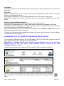
1
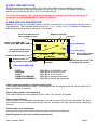
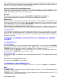
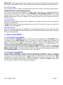
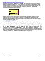
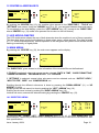
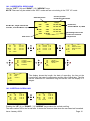
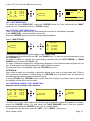
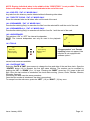
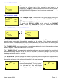
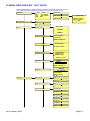
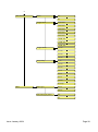
NAGRA ARES-BB
MANUAL
Version: Jun. 2004
WARNING: The ARES-BB has a built-in charger (charge current = 300mA).
NiCd or Ni-Metal-Hydride cells can be used.
WHEN USING THE EXTERNAL POWER SUPPLY, CHECK THAT THE
CHARGER SWITCH INSIDE THE BATTERY COMPARTIMENT IS “OFF”
BEFORE INSTALLING DRY CELLS.
PN 2019 615 150
CONTENTS
Page
1DELIVERED WITH. ....................................................................................... 4
2 INSTALLING THE BATTERIES..................................................................... 4
3 INSTALLING THE FLASHCARD. .................................................................. 4
4 POWER ON, POWER OFF........................................................................... 4
5 CONTRAST. ................................................................................................ 4
6 BUTTONS. .................................................................................................. 5
7 ARES-P II or ARES-BB DIFFERENCES. ....................................................... 5
8 FIRST TIME SWITCH ON. ............................................................................ 6
9 MAIN DISPLAY DESCRIPTION. ................................................................... 6
Status of the ARES-BB ................................................................................ 6
10 RECORD (2), REWIND (3), STOP (4), PLAY (5), FORWARD (6), MARKER
(14) KEYS ...................................................................................................... 7
10.1 RECORD KEY (2) ................................................................................ 7
10.2 REWIND KEY (3) AND FORWARD KEY (6) .......................................... 7
10.3 STOP KEY (4)...................................................................................... 8
10.4 PLAY KEY (5) ...................................................................................... 8
11 LEVEL ADJUSTMENT................................................................................ 8
11.1 OUTPUT LEVEL ADJUSTMENT........................................................... 8
11.2 INPUT LEVEL ADJUSTMENT............................................................... 8
11.3 THRESHOLD ADJUSTMENT ............................................................... 9
12 CENTER & ARROW KEYS........................................................................10
13 LED MODULOMETER...............................................................................10
14 MAIN MENU. ............................................................................................10
14.1 DIRECTORY MENU. ...........................................................................10
14.1.1 HORIZONTAL SCROLLING. .........................................................12
14.1.2 VERTICAL SCROLLING. ..............................................................12
14.1.3 QUIT DIRECTORY. ......................................................................13
14.1.4 TITLING, “NFS” MODE ONLY........................................................13
14.1.5 ERASING TAKE(S), “NFS” MODE ONLY. ......................................13
14.1.6 DELETE, “FAT 16” MODE ONLY. ..................................................14
14.1.7 DELETE TO END, “FAT 16” MODE ONLY......................................14
14.1.8 RENUMBER, “FAT 16” MODE ONLY. ............................................14
14.1.9 RENUMBER ALL, “FAT 16” MODE ONLY. .....................................14
14.2 LOUDSPEAKER. ................................................................................14
14.3 TOOLS. ..............................................................................................14
14.3.1 DATE AND TIME. .........................................................................14
14.3.2 CARD FORMATTING, “NFS” MODE ONLY. ...................................15
14.3.3 CARD FORMATTING, “FAT 16” MODE ONLY................................15
14.3.4 FORMAT REPAIRING, “NFS” MODE ONLY. ..................................15
14.3.5 PROGRAM SELECT. ....................................................................15
14.3.6 CONTRAST. .................................................................................16
14.3.7 VERSION. ....................................................................................16
14.4 TEMPLATES, “FAT 16” MODE ONLY...................................................16
14.5 SETTINGS MENU. ..............................................................................17
Issue: January 2004
Page 2
14.5.1 INPUT FILTER. .............................................................................17
14.5.2 ALC..............................................................................................17
14.5.3 ALC THRESHOLD. .......................................................................17
14.5.4 ALC REACTION SPEED. ..............................................................18
14.5.5 BEEP. ..........................................................................................18
14.5.6 COMPRESSION, “NFS” MODE ONLY. ..........................................18
14.5.7 FILE FORMAT, “FAT 16” MODE ONLY. .........................................18
14.5.8 BACKLIGHT. ................................................................................18
14.5.9 OUTPUT MODE. ..........................................................................19
14.5.10 OUTPUT LEVEL. ........................................................................19
14.6 AUTO RECORD, “FAT 16” MODE ONLY..............................................19
14.7 MIKE ..................................................................................................20
14.7.1 48V PHANTOM MIKE POWER. .....................................................20
14.7.2 MIKE TYPE, “FAT 16” MODE ONLY. .............................................20
15 LOCKING THE SETTINGS. .......................................................................21
16 LOCKING THE KEYPAD. ..........................................................................21
17 AUTO POWER OFF ..................................................................................21
18 MESSAGES..............................................................................................21
18.1 IN “NFS” MODE ..................................................................................21
18.2 IN “FAT 16” MODE ..............................................................................22
19 SOFTWARE UPDATE ...............................................................................22
20 MENU TREE ARES-BB, “NFS” MODE .......................................................23
21 MENU TREE ARES-BB, “FAT 16” MODE ...................................................25
22 INPUTS, OUTPUTS & SPECIFICATIONS ..................................................29
22.1 LEFT SIDE .........................................................................................29
22.2 OUTPUT SIDE ....................................................................................29
22.3 SPECIFICATIONS ..............................................................................30
23 ARES-BB “NFS” MODE, PC SOFTWARE & INSTALLATION.......................31
23.1 ARES-BB SOFTWARE, “NFS” MODE, USING A PC PCMCIA SLOT .....31
23.2 ARES-BB SOFTWARE, “NFS” MODE, USING A PC USB PORT...........31
24 ARES-BB “FAT 16” MODE, PC DRIVERS & INSTALLATION.......................32
25 SAFETY/COMPLIANCE ............................................................................33
Issue: January 2004
Page 3
1DELIVERED WITH.
1 Jack 6.3 mm (90 degrees) connector, 1 user manual, 1 USB cable, 1 CDR with Ares Import and
Digigram Import software.
2 INSTALLING THE BATTERIES.
On the rear side of the machine, loose the 2 “thumb” screws until the battery box can be removed. To
open the battery compartment, slide the inner cover until it is fully open. If dry cells are used verify that
the battery compartment switch is in the OFF position. Install the 6 “AA” cells observing the polarity
and replace the inner cover. Lock the battery compartment back to the machine.
Important note:
When using the external power supply, check that the switch on the battery compartment is set to
“OFF” before installing dry cells.
In the OFF position, the charger circuitry is not activated and if an external power supply is connected,
the machine will run from external supply and not from the batteries.
When an external power supply is connected to the Ares-BB, the green led turns on. During charge,
the yellow led turns on. The Ares-BB charges with approx. 300 mA. Charging stops automatically
(yellow led starts blinking slowly and finally turns off). If the charger switch is turned on and no
batteries are installed while the machine receives external power, the yellow led starts blinking fast.
3 INSTALLING THE FLASHCARD.
Insert the flashcard on the right side of the machine and push it fully home (eject button fully out).
Compact flash cards must be installed using an adapter.
NOTE: The software version, for the Ares -BB V2.00 and higher allows using linear and Strata flash
cards, ATA cards, compact flash cards and Micro-drive cards.
Important note:
When running the machine in the FAT 16 mode, only ATA, Compact flash cards and Micro-drive cards
can be used.
4 POWER ON, POWER OFF.
Press the “POWER ON” button (1) for 1 second and the machine switches on. To switch “OFF” the
machine push the same button again for 1 second.
Attention: the machine cannot be switched OFF during RECORD.
5 CONTRAST.
If the display contrast is not set properly at power on, switch off the machine, keep the “RIGHT” arrow
key (12) pressed while turning on the machine. This brings the machine directly to the contrast menu.
Adjust step-by-step with the “UP” (9) or “DOWN” (11) arrow keys to increase or decrease accordingly.
Once the correct contrast is found, press the “CENTER” key (13) to store the new setting in the
machine. Press the “LEFT” arrow key (10) to quit the menus. The factory setting has the value “32”.
Issue: January 2004
Page 4
6 BUTTONS.
1
2
3
4
5
6
7
8
Power ON / OFF
Record, Marker key
Rewind, skip backwards key
Stop key
Play key
Forward, skip forwards key
Reduce input sensitivity or playback
level key
Increase input sensitivity or
playback level key
9
10
11
12
13
14
15
Up arrow key or increase output
level key
Left arrow key
Down arrow key or reduce output
level key
Right arrow key
Other menu or execute key
Marker
Keypad lock
7 ARES -P II or ARES-BB DIFFERENCES.
ARES- P II & ARES-BB: Is equipped with a USB 1.1 connector. In the “FAT 16” mode only, the
machine is recognized as an external removable hard drive. It also has a built-in speaker, Phantom
power, Vortex filter and accepts compact micro-drives up to 2 GB.
The ARES-BB is functionally identical to the ARES- P II. It offers the USER XLR input & output
connectors and an ergonomic table-top operation. It gives a 20% increase in autonomy thanks to the
additional batteries and can offer a Lithium-Ion pack as an alternative. The ARES-BB cannot use the
NP-MICE/NP-MICES Electret microphone capsules.
Without any software options installed, the card is formatted “FAT 16” and is directly compatible with
Windows or Mac O/S. The recorded files are Broadcast Wave Format (xxx.wav). Only PCM can be
recorded (not compressed).
If equipped with the software option I, the machine emulates also an ARES-P. In the “NFS” (Nagra File
System) mode, compressed MPEG files can be recorded. In the “FAT 16” mode, the maximum bit rate
becomes 384kb/s 48kHz stereo.
Only ATA, Compact flash or Micro-drive cards can be used in the “FAT 16” mode.
If equipped with software option I & II, the machine also emulates an RCX220. This means that in the
“NFS” mode, via USB, Windows recognizes the machine as an external soundcard and in the “FAT
16” mode as an external removable hard drive.
Important note: When making linear recordings (WAV) the range of media that can be used is
restricted. The card must be capable of writing data at high speed. A stereo recording at 48kHz
requires a data rate of 2 x 16 bits x 48000 sampling frequency divided by 8 bits per Byte gives a data
rate of 192 kBytes per second.
Issue: January 2004
Page 5
8 FIRST TIME SWITCH ON.
Verify first that the keypad lock switch (15) is in the left position. Once the batteries have been
installed and turning on, the machine will sw itch on in the FAT 16 mode. The display will show a
picture of a cylinder with the word “FAT” for several seconds.
To change the mode to “NFS” mode (if the software #1 package is included) jump to page 15
Paragraph 14.3.4 PROGRAM SELECT before continuing.
9 MAIN DISPLAY DESCRIPTION.
Attention: At power on, the display below is shown, but without the level bargraph indicator on the
right-hand side. This bargraph appears when the “+” or “-” button (8 or 7) is pressed. It disappears
after a few seconds to improve the clarity of the display.
Input level indication for
Left and Right channel
Headroom indicator
Input level
1
2
Status of the ARES-BB
STOP, PLAY, REC, FWD, RWD
-21
-9
Battery status
Total number of recorded takes
+9
In
007
Level adjustment
0:00
- 20dB
Take number and position
in minutes and seconds
Status of the flashcard
0
12 Takes
R:
Low Battery
Level setting
Stop or play position
on the flashcard
4:08:26
Messages
Remaining time on the card
in minutes and seconds
Status of the ARES- BB
“STOP”
“RECORD”
“PLAY”
“SEARCH FORWARD”
“SEARCH BACKWARD”
ARES-BB is in STAND BY mode
ARES-BB is in RECORD mode
ARES-BB is in PLAY mode
ARES-BB is playing fast forwards
ARES-BB is playing fast backwards
Take number and position in minutes and seconds
This is the physical playback position. The example shows that playback will start at the beginning of
take 7 (0 minutes, 0 seconds).
Stop or play position on the flashcard
The marker shows the exact playback position, take 7 at 0 minutes, 0 seconds.
Status of the flashcard
The full length of the bargraph corresponds to the total memory of the inserted flashcard. The black
area shows how much memory was already used for recording. The clear area shows the remaining
memory.
Total number of recorded takes
This area shows the total number of takes already recorded on the flashcard.
Remaining time on the card in minutes and seconds
Issue: January 2004
Page 6
This indicates how much recording time is left on the card. In this example, it shows 8 minutes, 8
seconds. If the bit-rate is changed, it will automatically be updated. Example 8:08 if 128kb/s was set, it
will become 16:16 if the bit-rate was changed to 64kb/s.
Input level indication for Left and Right channel
In the stereo mode, bargraph 1 corresponds to the left channel and 2 to the right channel. In mono
mode, both bargraphs indicate the input level. From 0dB, the bargraph shows the headroom up to
+9dB. +9dB corresponds to “FF” for the AD converter.
Messages
This is the area for messages, such as “LOW BATTERY”, CARD FULL, NO CARD, etc.
A beep in the headphones corresponds to an arrival of a message on the display.
Battery status
When the battery icon shows full, it indicates the batteries are fully charged. Full corresponds to a
voltage measurement of 7.54V or higher. When the voltage drops below 6V, a warning beep is heard
in the headphones and the message “LOW BATTERY” appears in the display. When the voltage
drops below 5.1V the machine automatically switches off.
When the battery icon disappears during a USB connection in the “FAT 16” mode, it means that the
machine is powered by the PC and not anymore by the internal batteries or external power supply.
Level Adjustment
This bargraph only appears on the screen during the adjustment of the input sensitivity, the output
level or the ALC threshold adjustment. If no adjustment is made it will disappear after a few seconds.
Simultaneously, the level setting in dB’s as well as the kind of adjustment “IN”, “OUT” or “THR” will
appear on the display.
10 RECORD (2), REWIND (3), STOP (4), PLAY (5), FORWARD (6), MARKER
(14) KEYS
10.1 RECORD KEY (2)
For “NFS” mode.
A valid formatted card must be fitted and the machine switched ON. To start recording, the “RECORD”
key (2) can be pressed, even if the machine was in “PLAY” mode or is in one of the sub-menus. The
“RECORD” key will not work if the machine is deleting a take or formatting the card.
If during record the “RECORD” key is pressed again, a new take is automatically created. This
function is used for “MARKING” the audio during record.
For “FAT 16” mode.
During record or play, the “MARKER” key (14) can be pressed on the fly. This will add a marker inside
a single file.
During record, the front red LED turns ON.
During record, the “POWER” key is disabled.
10.2 REWIND KEY (3) AND FORWARD KEY (6)
These keys have two functions called “SKIP” backwards or forwards and “REWIND” or “FORWARD”.
SKIP.
For “NFS” mode.
In “STOP” mode: To jump take-by-take, pressing briefly on the “<<” or “>>” keys will decrement or
increment the take position.
In “PLAY” mode: To jump to other takes on the card, press twice in quick succession the “<<” or “>>”
to decrement or increment the take number.
Issue: January 2004
Page 7
IMPORTANT: Only takes with the same compression as the current settings of the machine can be
played back using the SKIP buttons. All other takes with a different compression cannot be selected.
For “FAT 16” mode.
If the recording contains “markers” then these keys will jump to the next (or previous) marker position.
FORWARD SEARCH & BACKWARD SEARCH.
This function can be executed in “STOP” or “PLAY” mode. Once the “>>” or “<<”key is pressed for
more than 0.5 seconds, the machine starts “FORWARD or BACKWARDS SEARCH” at 4 times
nominal speed. The longer the button is pressed, the search speed increments up to 128 times
nominal speed. When the button is released, the search stops and it returns to its previous function
(STOP or PLAY).
10.3 STOP KEY (4)
When this key is pressed during record or playback, the machine stops recording or playing and
returns to the “EE” mode.
The “EE” mode means that the input signal is fed to the output. This button can also be used as the
“PAUSE” key during playback.
10.4 PLAY KEY (5)
After a record session pressing the “PLAY” key, immediately plays back the last recorded take. After
power on pressing “PLAY” will resume playback from its last position before power down, as long as
the batteries are installed.
11 LEVEL ADJUSTMENT
11.1 OUTPUT LEVEL ADJUSTMENT
During the “STOP” or “RECORD” mode, the output level can be adjusted by the “UP ARROW” key (9)
to increase or the “DOWN ARROW” key (11) to decrease. Once one of these keys is pressed, an
additional bargraph on the right side of the display appears, indicating “OUT”, showing the current
position of the adjustment. “0dB” corresponds to maximum output level, -“59dB” corresponds to
minimum output level and “OFF” corresponds to mute of the output signal.
The setting of the output level can also be stored in the machine in such a way that every time the
machine is switched ON, it will take the same “DEFAULT LEVEL ” output adjustment (See “SETTINGS
MENU, OUTPUT LEVEL ”). During the “PLAY” mode, the output level can be adjusted either by the
“UP & DOWN ARROW” keys (9 & 11) or the “+” and “-“keys (8 & 7).
11.2 INPUT LEVEL ADJUSTMENT
During “STOP” or “RECORD”, the input level can be adjusted by pressing the “+” (8) or “-“ (7) keys to
increase or decrease the input sensitivity. Once one of these keys is pressed, an additional bargraph
on the right side of the display appears, indicating “IN”, corresponding to the current setting. “74dB”
corresponds to maximum input gain, “133dB” corresponds to minimum input gain and “OFF”
corresponds to muting of the input signal. If the input sensitivity is adjusted for “74dB”, it means that if
the input signal at 74dB SPL will be recorded at a 0dB level.
Issue: January 2004
Page 8
Level Adjustment in the stereo mode (FAT 16 only)
When in the sub menus the “MIKE” is set to “STEREO”, the left and right channel can be adjusted
separately. Holding the left arrow key (10) and adjusting the input sensitivity will only adjust the left
channel. Holding the right arrow key (12) and adjusting the input sensitivity will only adjust the right
channel. When the input sensitivity between the 2 channels is not identical, the display will
automatically show both input sensitivity levels.
1
2
-21
-9
0
+9
In
007
0:00
84 dB/94 dB
12 Takes
R:
8:08
As shown on the picture, the red indications correspond to the left channel, the blue indications
correspond to the right channel. If no left or right arrow is pressed during the input sensitivity
adjustment, both channels will be adjusted simultaneously and keep the same delta until one of the
channels is reaching max. or min. level.
11.3 THRESHOLD ADJUSTMENT
The “THRESHOLD” adjustment permits selection of the size of the compression zone. It is the lower
limit setting of the zone that will be automatically amplified during a silent period. The “ALC” works in a
range of 42dB (from 74dB to 116dB). If the “THRESHOLD” is set to 104dB, signals of 104dB and
higher (max. 116dB) will be recorded at 0dB level (between –2dB and –6dB for a stable signal). A
signal of 90dB will be recorded at –14dB (104dB – 90dB). If “ALC” (Automatic Level Control) is “ON”
and the “ALC THRESHOLD” is set to “USING +/- KEYS” (see SETTINGS MENU, ALC
THRESHOLD), the threshold during “RECORD” or “STOP” can be adjusted by pressing the “+” or “-“
keys (8 or 7). Once one of these keys is pressed, an additional bargraph on the right side of the
display, indicating “THR” appears, showing the current position of the adjustment. “74dB” corresponds
to maximum threshold level, “104dB” corresponds to minimum threshold level.
Issue: January 2004
Page 9
12 CENTER & ARROW KEYS
1
2
-21
-9
0
007
+9
0:00
Directory
Tools
12 Takes
R:
Directory
Tools
Settings
4:08:26
By pushing the “CENTER” key (13), the machine gives access to the “DIRECTORY”, “TOOLS” and
“SETTINGS” sub-menus. Using the “ARROW” keys (9 to 12), you navigate between those sub-menus.
To move back to the initial display, press the “LEFT ARROW” key (10) (except in the “DIRECTORY”
where “CENTER” key (13) needs to be pressed first to return to the sub-menus).
13 LED MODULOMETER
The LED modulometer shows the sum of both channels when the machine is set to Stereo operation.
The three leds give a quick visual indication in three colors, green, yellow and red. They light at levels
of – 21, -9 and 0 dB respectively. Normal operation is with the green and yellow led on and the red led
flashing occasionally on signal peaks.
14 MAIN MENU.
By pressing the “CENTER” key (13), the main menu appears on the display.
1
2
-21
-9
0
001
+9
0:00
Directory
Tools
12 Takes
R:
4:08:26
The “DIRECTORY” gives access to all the information of the recorded files on the flashcard.
If “TOOLS” is selected, other sub menus can be selected: “DATE & TIME”, “CARD FORMATTING”,
“FORMAT REPAIRING”, ”PROGRAM SELECT” and “VERSION”.
If “SETTINGS” is selected, several other sub-menus can be selected such as: “OUTPUT LEVEL ”,
“INPUT FILTER”, “BEEP” and “COMPRESSION” etc.
Scrolling through the different sub-menus is done by pressing the “DOWN ARROW” (11) or “UP
ARROW” (9) keys.
Escaping from the sub-menu’s is done by pushing the “LEFT” ARROW” key (10).
Entering a sub-menu is done by pushing the “RIGHT ARROW” key (12).
Inside a sub-menu, execute the selected setting by pressing the “CENTER” key (13).
14.1 DIRECTORY MENU.
1
2
-21
-9
0
001
+9
0:00
Directory
Tools
12 Takes
R:
000
001
002
003
End
000
0.00
1.25
3.48
4.24
4:08:26
0.00
12 / 03 / 00
12 / 03 / 00
13 / 03 / 00
13 / 03 / 00
4:08:26
By using the “UP”, “DOWN”, “LEFT”, “RIGHT ARROW” keys ( 9, 11, 10, 12), once “DIRECTORY” has
been selected, it becomes possible to scroll vertically and horizontaly to view all the recorded files and
their specifications.
Issue: January 2004
Page 10
If the marker has a “
of the machine.
” shape, it means that the take compression is the same as the current settings
If the marker has a “ >” shape, it means that the take compression is different from the current settings
of the machine.
In the latter case, if the “PLAY” button” (5) is pressed, the corresponding compression will be
automatically loaded in the DSP, and play starts.
If the marker is in front of one of the audio takes, the “PLAY”, “STOP”, “FWD” and “RWD” function
keys (3,4,5 &6) become active.
If the “RECORD” button (2 or 2bis) is pressed, the display returns to the main screen and the
recording starts.
Issue: January 2004
Page 11
14.1.1 HORIZONTAL SCROLLING.
Use the ”LEFT” (10) and “RIGHT” (12) “ARROW” keys.
NOTE: Titles can only be added in the “NFS” mode and are not existing in the “FAT 16” mode
Current position
inside the selected file
Selected file No
File No 001, length 1minute 25
seconds, recorded March 12, 2000
000
001
002
003
End
002
0.00
1.25
3.48
4.24
4:08:26
1.30
12 / 03 / 00
12 / 03 / 00
13 / 03 / 00
13 / 03 / 00
Remaining time on the
card at the selected
compression
End of list
000
001
002
003
End
000
0.00
1.25
3.48
4.24
4:08:26
0.00
12 / 03 / 00
12 / 03 / 00
13 / 03 / 00
13 / 03 / 00
000
001
002
003
End
000
001
002
003
End
000
001
002
003
End
002
3.48
12 / 03 / 00 10 : 41
12 / 03 / 00 10 : 55
13 / 03 / 00 11 : 25
13 / 03 / 00 14 : 19
002
3.48
< No title >
FOOTBALL GAME IN
< No title >
ACCIDENT
002
3.48
< No title >
PARIS
< No title >
000
001
002
003
End
Format file,
created March 12, 2000
000
001
002
003
End
002
3.48
Format
MPEG 192 / 48 ST.
MPEG 128 / 24 ST.
G.722
002
3.48
< No title >
GAME IN PARIS
< No title >
The display shows the length, the date of recording, the time at the
record start, the type of compression and the title of each take. The title
can be maximum 31 characters long and scrolls over the display in 3
stages.
14.1.2 VERTICAL SCROLLING.
000
001
002
003
End
000
0.00
1.25
3.48
4.24
4:08:26
0.00
12 / 03 / 00
12 / 03 / 00
13 / 03 / 00
13 / 03 / 00
000
001
002
003
End
000
0.00
1.25
3.48
4.24
4:08:26
0.00
12 / 03 / 00
12 / 03 / 00
13 / 03 / 00
13 / 03 / 00
Pushing the “UP” (9) or “DOWN” (11) “ARROW” keys makes the vertical scrolling.
The take number 000 is the format take. It shows the time and date when the card was last formatted.
Issue: January 2004
Page 12
In the “FAT 16” mode, take 000 does not exist.
000
001
002
003
End
000
0.00
1.25
3.48
4.24
4:08:26
0.00
12 / 03 / 00
12 / 03 / 00
13 / 03 / 00
13 / 03 / 00
1
2
-21
-9
0
002
+9
0:00
Quit directory
Take erasure
3 Takes
R:
4:08:26
14.1.3 QUIT DIRECTORY.
To escape from the “DIRECTORY”, press the “CENTER” button (13) once followed by the “RIGHT”
arrow key (12). The display returns to “STATUS” display.
14.1.4 TITLING, “NFS” MODE ONLY.
Titles can be added to the format file (000) and each sound file for identification purposes.
In the “DIRECTORY”, select the take for a new title.
Press the “CENTER” key once and the following display appears:
Select “TAKE TITLING”.
Title take 036
Stop
Play
>>
Rec.
Quit directory
Take titling
key = Escape
key = Delete
key = Insert
key = Write it
Pressing the “STOP” key returns the display to the “DIRECTORY”.
Characters can be selected with the “UP” and “DOWN” keys. To enter the selected character, press
the “CENTER” key.
To delete a character, highlight the corresponding character with the “LEFT ARROW” or “RIGHT
ARROW” keys and press the “PLAY” key.
To insert a character, highlight the corresponding character for the insertion area and press the “>>”
key. All characters from the highlight position will be shifted one space.
To record the title on the flashcard, press the “RECORD” key once.
ATTENTION:
Once a title is added to a recording, it cannot be altered in any way on a linear flash card. Titles on
ATA cards can be modified. If during titling, the “RECORD” key is pressed twice, the title will be
recorded and the machine starts a new audio record.
If during “TITLING” the “RECORD” button on the side of the machine is pressed, audio record starts
immediately and the title is not recorded.
14.1.5 ERASING TAKE(S), “NFS” MODE ONLY.
Example: take 2 and higher take numbers
000
001
002
003
End
000
0.00
1.25
3.48
4.24
4:08:26
0.00
12 / 03 / 00
12 / 03 / 00
13 / 03 / 00
13 / 03 / 00
Quit directory
Take erasure
Quit directory
Take erasure
To delete one or more takes, select in the directory the lowest take number that needs to be deleted,
press the “CENTER” button (13) and select the “TAKE ERASURE” menu. Once the selection
confirmed by pressing the “CENTER” button (13), the erasing starts.
To escape from the sub-menu, press the “LEFT” (10) or “RIGHT” (12) key onc e.
Issue: January 2004
Page 13
NOTE: Erasing individual takes in the middle of the “DIRECTORY” is not possible. The erase
feature will always erase from the selected take to the end of the card.
14.1.6 DELETE, “FAT 16” MODE ONLY.
Any take from the directory can be deleted without influencing other takes.
14.1.7 DELETE TO END, “FAT 16” MODE ONLY.
Erase the selected take and all takes after until the end of the card.
14.1.8 RENUMBER, “FAT 16” MODE ONLY.
Permits after deleting file(s) to renumber the files from the selected file until the end of the card.
14.1.9 RENUMBER ALL, “FAT 16” MODE ONLY.
Permits after deleting file(s) to renumber all the files from file 1 until the end of the card.
14.2 LOUDSPEAKER.
This switches “ON” or “OFF” the internal loudspeaker.
NOTE: The internal o
l udspeaker can only be used in the playback
mode.
On
14.3 TOOLS.
Tools
Loudspeaker
Off
On
Tools
Date & Time
Card formatting
Format repairing
Program select
Format repairing
Version
“Program select” and “Format
repairing” does not appear if the
machine is not equipped with
software option I.
several sub-menus are available.
14.3.1 DATE AND TIME.
Selecting “DATE & TIME” gives access to change the time and date of the real time clock. Once the
“CENTER” button (13) is pressed, the first digit starts blinking. The number can be modified by
pushing the “UP” or “DOWN” (9 or 11) keys. Pressing the “RIGHT” arrow key (12) jumps to the next
digit. Once the last number is introduced, the clock starts running. (Hours, Hours, Minutes, Minutes,
Seconds, Seconds)
Introducing the date uses the same procedure.
Once the last number is introduced, the date is memorized.
To escape from the sub-menu, press the “LEFT” (10) or “RIGHT” (12) key once.
Issue: January 2004
Page 14
14.3.2 CARD FORMATTING, “NFS” MODE ONLY.
Card formatting
Card present.
PRESS CENTER KEY.
Card formatting
Card formatting
Card present.
Card not empty.
Card present.
Formatting . . .
RIGHT KEY TO CONFIRM.
100%
Format completed.
Execute by pressing the “RIGHT” arrow key (12) and the card formatting will begin.
Once the formatting is finished, the display returns to the previous menu.
To escape from the sub-menu, press the “LEFT” (10) or “RIGHT” (12) key once.
When the format command is executed, “CARD NOT EMPTY” appears if one or more takes are on
the card (including format take 000).
14.3.3 CARD FORMATTING, “FAT 16” MODE ONLY.
Format card
Format card
Format card
Format card (FAT16)?
Format card (FAT16)?
The current content of
Format card (FAT16)?
PRESS CENTER KEY.
the card will be lost!
RIGHT KEY TO CONFIRM.
Formatting.
Execute by pressing the “RIGHT” arrow key (12) and the card formatting will begin.
Once the formatting is finished, the display shows “Done”.
To escape from the sub-menu, press the “LEFT” (10) or “RIGHT” (12) key once.
14.3.4 FORMAT REPAIRING, “NFS” MODE ONLY.
If during record, the card was removed (or batteries removed), an
“UNCLOSED FILE” will be left on the card. This utility allows the user to
close this file correctly.
”FORMAT CORRUPTED” will be shown.
FORMAT REPAIRING
FORMAT REPAIRING
UNCLOSED FILE.
RECOVER ?
UNCLOSED FILE.
RECOVER ?
PRESS CENTER KEY.
RECOVER COMPLETE.
1
2
-21
-9
0
003
+9
0:00
FORMAT CORRUPTED
FORMAT REPAIRING
NO FORMAT PROBLEMS.
Follow the instructions on the display to recover the take. The last recorded file will be closed at the
end of the memory of the card. The remaining time becomes 0 min. 0 sec.
To escape from the sub-menu, press the “LEFT” (10) or “RIGHT” (12) key once.
14.3.5 PROGRAM SELECT.
PROGRAM SELECT
FAT 16 FILE SYST.
NAGRA FILE SYST.
The program select permits to swap between the 2 recording modes
“FAT 16” mode or “NAGRA” mode (“NFS”) compressed files.
This sub menu does not appear if software option I is not installed.
To escape from the sub-menu, press the “LEFT” key (10) once.
NAGRA FILE SYST.
Issue: January 2004
Page 15
14.3.6 CONTRAST.
Contrast
TEST 34
Current contrast = 32
This menu permits to adjust the contrast of the display. Pressing the
“UP” (9) or “DOWN” (11) key changes the current contrast. Pressing the
“CENTER” key (13) stores the contrast settings as a default value at
power on.
Default contrast = 33
To escape from the sub-menu, press the “LEFT” key (10) once.
14.3.7 VERSION.
ARES-BB
S/N : 123456789
Soft (FAT): Vx.xx
Audio board: 2
Software options:
#1 #2
Selecting the “VERSION” sub-menu shows the serial number of the
recorder as well as current version of the software installed. The version
shown in this picture corresponds to the version for the “FAT 16” mode.
Turning on the machine in the “NFS” mode will show the “NFS” version.
To escape from the sub-menu, press the “LEFT” key (10) once.
14.4 TEMPLATES, “FAT 16” MODE ONLY.
The Ares -BB can store and recall 4 different templates.
To have an overview of the different sub-menu settings that can be
stored, refer to the menu tree at the end of this
XXX
manual. Only menu settings with a red square
against it can be stored.
To use a template, setup the machine as required, then go to
“TEMPLATES”, select “STORE 1” and press the execute key (13). The message “DONE” will appear.
If now any changes were made in the setup, you can go to “RECALL 1” and press the execute key
once again. This returns the machine to the settings stored in template 1.
Templates
Recall 4
Store 1
Store 2
Issue: January 2004
Page 16
14.5 SETTINGS MENU.
The settings menu gives access to several sub-menus.
Settings
Settings
Input filter
ALC
ALC threshold
Settings
ALC
ALC threshold
ALC speed
On
ALC threshold
ALC speed
Beep
Normal
Using +/- keys
Settings
Settings
ALC speed
Beep
Compression
Beep
Compression
Backlight
On
Settings
Compression
Backlight
Output level
MPEG 128/48
The current setting of each is always shown at the bottom of the display.
In “NFS” mode, “COMPRESSION” is shown, in the “FAT 16” mode, the
name compression is replaced by “FILE FORMAT”.
Automatic
14.5.1 INPUT FILTER.
Input filter
Two possibilities are available: “FLAT” or “LOW CUT”.
Flat
Low cut
Flat
14.5.2 ALC.
ALC
From this sub-menu, the “ALC” can be switched “ON” or “OFF”.
It is highly recommended to switch on the “LOW CUT” filter if “ALC” is
turned ON.
On
Off
On
14.5.3 ALC THRESHOLD.
ALC threshold
-74 dB
Using +/- keys
The “THRESHOLD” can be adjusted from –104 dB to –74 dB.
In this case the “+”key (8) and the “-“key (7) are disabled. If “USING +/KEYS” is selected, the “+”key (8) and “-“key (7) are enabled during
“STOP” and “RECORD” mode, which allows the “THRESHOLD” level to
be adjusted without returning in the “SETTINGS” menu.
Using +/- keys
Issue: January 2004
Page 17
14.5.4 ALC REACTION SPEED.
ALC speed
Fast
Normal
Slow
The “ALC SPEED” can be set to a “FAST”, “NORMAL” or “SLOW”
reaction time.
Normal
14.5.5 BEEP.
Beep
The beep signal is only available at the output and is not recorded. It
can be switched “ON” or “OFF”.
Off
On
On
14.5.6 COMPRESSION, “NFS” MODE ONLY.
Compression
MPEG 64/16
MPEG 128/48
MPEG 128/24
MPEG 64/48
17 different types of compression can be selected.
Use the “UP” (9) or “DOWN” (11) arrow keys to select the type of
compression to be used and press the “CENTER” key (13) to select
one.
The display returns to the previous menu.
Example : MPEG 64/48 stands for: MPEG 1Layer II MONO compression at a total bit-rate of 64kb/s
using a sampling frequency of 48kHz.
MPEG 192/48 ST stands for: MPEG 1 Layer II STEREO compression at a total bit-rate of 192kb/s
(96kb/s per channel) using a sample rate of 48kHz.
14.5.7 FILE FORMAT, “FAT 16” MODE ONLY.
File format
PCM 48K
PCM 44K1
PCM 32K
The Ares-BB without any soft option can only record in a linear mode
(not compressed). If the soft option I is installed it includes also the
selection of MPEG compression and this time up to 384kb/s.
MPEG 256/48 St.
14.5.8 BACKLIGHT.
The backlight can be set to always “OFF”, always “ON” or “AUTOMATIC”.
In the “AUTOMATIC” mode, the backlight turns on for 15 seconds, each time a key is pressed.
Backlight
Off
On
Automatic
On
Issue: January 2004
Page 18
14.5.9 OUTPUT MODE.
This sub-menu permits to turn on or off the sound to the output
connector in the case that a little speaker is used instead of a
headphone. “ALWAYS” means that the output sound is always present.
“ONLY IN PLAYBACK” means that the output sound is present only
during playback but not present in the record mode or EE mode.
Output mode
Always on
Only in playback
Always on
14.5.10 OUTPUT LEVEL.
The “CURRENT LEVEL ” corresponds to the setting before entering the
sub-menu. To modify this level, press the “UP” or “DOWN” keys (9 or
11).
The “DEFAULT LEVEL ” is the level that has been saved in the memory.
To modify the “DEFAULT LEVEL ” to the value of the “CURRENT
LEVEL ”, press the “CENTER” Key (13). The default value will be
remembered even if the unit loses power.
Output level
Current level =
Default level =
- 6 DB
- 9 DB
14.6 AUTO RECORD, “FAT 16” MODE ONLY.
Auto record
Auto record
Mode
Trigger level
Trigger delay
Trigger level
Trigger delay
Stop delay
50 dB SPL
0.0 sec.
The “AUTO RECORD” menu permits to turn on or off the auto record mode. This mode of recording
permits to start a recording automatically depending on the settings of the different parameters
described below. Once the parameters set, put the machine in the record mode. The recording will
start once the requested level and length of any incoming sound is obtained.
The “TRIGGER LEVEL ” sub-menu permits to adjust the level detection to start the recording and can
be set in steps of 10 dB from 50 dB SPL to 120 dB SPL.
The “ TRIGGER DELAY” menu permits to adjust the continuous duration or length of the sound level
before the recording starts. It can be set from 0.0 seconds to 1 second. Example: if you clap your
hands a single time and the start delay is set to 0.1 second, the recording will not start, as the
handclap was shorter than 0.1 seconds.
The “STOP DELAY” permits to adjust the duration of recording once the sound level drops below the
threshold level and can be set from 5 seconds up to 15 minutes or nonstop. Once the delay is passed,
the machine will return to the waiting position ready for the next recording
1
2
-21
-9
59 dB
007
0
+9
0:00
Auto
12 Takes
R:
8:08:50
Issue: January 2004
The left picture shows the machine ready
to record automatically. The right picture
shows the machine in the record mode.
The Ares-BB can also be stopped
manually by pressing the Stop button (4).
1
2
-21
-9
59 dB
008
0
+9
0:06
Auto
13 Takes
R:
8:08:48
Page 19
14.7 MIKE
Mike
This menu gives access to the selection of the microphone type (routing,
Mono or Stereo) as well as the 48V power supply.
Mike type
48V, Mike power
48
14.7.1 48V PHANTOM MIKE POWER.
If Phantom microphones are used the 48V must be turned on. This
48V. Mike power
selection needs to be confirmed by pressing the right arrow key. On the
Off
main display, the text
will appear next to the battery status.
On
On
14.7.2 MIKE TYPE, “FAT 16” MODE ONLY.
If “MONO” is selected and a stereo pair of microphones is connected
and the “FILE FORMAT” is set to a mono recording, both channels will
Mike type
be mixed and reduced by 3 dB before they are recorded as a mono
Mono
channel.
Stereo
If “STEREO” is selected and a mono microphone is connected and the
“FILE FORMAT” is set to a stereo recording, only the left channel will be
Mono
recorded.
If “MONO” is selected and a mono microphone is connected and the
“FILE FORMAT” is set to a stereo recording, both channels will have the same signal.
Issue: January 2004
Page 20
15 LOCKING THE SETTINGS.
Settings
By pressing a certain combination of keys when turning on the
machine, the settings can then be locked step-by-step. This to prevent,
the user changing the settings inadvertenly or otherwise. To obtain the
combination code, contact your local NAGRA dealer.
Beep
Compression
Backlight
MPEG 128/48
Any sub-menu can be locked by pressing the “STOP” button or unlocked by pressing the “PLAY”
button. When the sub-menu has been locked, a closed padlock appears in front of the selected submenu. When the sub-menu has been unlocked, the closed padlock dissapears. To remove the
password, switch off and on again the machine.
16 LOCKING THE KEYPAD.
During record or playback the keyboard can be locked by setting the keypad switch (15) to ON. To
unlock the keyboard, set the same switch back to OFF. When the keypad is locked, the message
“Keypad lock” appears on the display
17 AUTO POWER OFF
When the machine is left in the “STOP” mode for 10 minutes, it will automatically switch off. During
the last 14 seconds of that period, the beep sounds every second. When any key is pressed, the
power counter will be reset.
To disable the auto power off, from the power off status , press and hold the center key while
pressing the power key.
In the case that the machine is turned on with the auto power disabled, the message “NO AUTO
POWER OFF” appears during a few seconds.
18 MESSAGES
18.1 IN “NFS” MODE
“LOW BATTERY”
“NO CARD”
“FORMAT CORRUPTED”
“CARD FULL”
“INVALID CARD”
“UNFORMATTED CARD”
“CARD WRITE PROTECTED”
“OPEN WRITE ERROR”
“WRITE ERROR”
“CARD NEARLY FULL”
“ERASE COMPLETED”
“FORMAT COMPLETED”
“CARD READ ERROR”
“READ ERROR”
“UNKNOWN FORMAT”
“CARD TOO SLOW”
“BUFFER OVERFLOW”
“AUTO POWER OFF”
“NO AUTO POWER OFF”
Issue: January 2004
The battery voltage has dropped too low
No card is inserted
Occurs if the card was removed during record or power lost
abruptly
No more record memory is available
The card is not recognized by the machine
The card is recognized but not formatted
Write protection switch on the card is ON
Defective card or card error
Defective card or card error
60 seconds recording time left on the card
At the end of erasure of one or several takes
At the end of a card formatting
Impossible to read the directory due to a defective card or
a read error
Read error during playback
The card is recognized but not the type of format
Depending from the selected file format, some cards do not
accept a high recording bit rate
Record buffer is full due to a slow card
The machine will switch of in the next 15 seconds
Auto power off has been disabled
Page 21
18.2 IN “FAT 16” MODE
"WRONG USB VERSION"
"CARD FULL"
"OPEN WRITE ERROR"
"WRITE ERROR"
"READ ERROR"
"CARD TOO SLOW"
"DIRECTORY FULL"
"CARD NEARLY FULL"
"KEYPAD LOCKED"
"AUTO POWER OFF"
"LOW BATTERY"
"NO AUTO POWER OFF"
"INVALID CARD"
"NO CARD"
"UNKNOWN FORMAT"
"DIR UNUSABLE"
"CARD READING..."
"CARD BUSY..."
"USB MODE"
DSP and USB software versions are incompatible
No more memory available on the card
Defective card or card error
Defective card or card error
Defective card or card error
Depending from the selected file format, some cards do not
accept a high recording bit rate
999 takes (files) already recorded
60 seconds recording time left on the card
The full keypad is locked
The machine will switch of in the nex t 15 seconds
The battery voltage has dropped too low
Auto power off has been disabled
The card is not recognized by the machine
No card inserted in the slot
The card is recognized but not the type of format
The “ARESP” folder cannot be created
Example: an ARESP file name was already present
Appears during the directory reading
Appears when the card is busy
Example: delete to end or renumbering
The card is accessed via USB
19 SOFTWARE UPDATE
A small black 6 pin connector is located just under the flashcard. This connector is a RS232
connector. A special adapter “NP-PCA” is needed to connect the RS232 from the machine to a PC or
laptop.
When new software from NAGRA becomes available, it can be delivered by Email or it can be downloaded from the NAGRA web site. By using the PC software called “PuserLoader” the machine can
be updated with the new software version. This takes about 2 to 3 minutes.
Issue: January 2004
Page 22
20 MENU TREE ARES-BB, “NFS” MODE
TREE CONFIGURATION, ARES-BB IN THE CASE OF NFS MODE (NAGRA FILE SYST.)
THIS TREE DOES NOT APPEAR IF SOFWARE OPTION #I IS NOT INSTALLED
Directory
000
0.00
>000
0.00 10/03/03
001
2.34 12/03/03
END
48.40
Quit directory
Take titling
Take erasure
Loudspeaker
Off
Title take 001
Stop key = Escape
Play key = Delete
....... .......ETC.
On
Tools
Date & Time
Date & Time
HH:MM.SS
DD.MM.YY
Card formatting
Card formatting
Card present
PRESS CENTER KEY.
Format repairing
Format repairing
No format problems.
Program select
Program select
FAT16 file syst.
NAGRA file syst.
NAGRA file syst.
Contrast
Contrast
TEST 34
Current contrast = 32
Default contrast = 32
Settings
Version
ARES-P II
S/N: 123456789
Soft (NFS): Vx.xx
Audio board: 2
Software options:
#1 #2
Input filter
Flat
Low cut
ALC
Off
On
ALC threshold
104 dB SPL
98 dB SPL
92 dB SPL
86 dB SPL
80 dB SPL
74 dB SPL
Using +/- keys
Issue: January 2004
Page 23
ALC speed
Fast
Normal
Slow
Beep
Off
On
Compression
G722
MPEG 64/48
MPEG 64/24
MPEG 64/32
MPEG 64/16
MPEG 128/48
MPEG 128/24
MPEG 128/32
MPEG 128/16
MPEG 128/48 st.
MPEG 128/24 st.
MPEG 128/32 st.
MPEG 128/16 st.
MPEG 192/48
MPEG 192/32
MPEG 192/48 st.
MPEG 192/32 st.
Backlight
Off
On
Automatic
Output mode
Always on
Only in playback
Output level
Output level
Current level = -1 dB
Default level = 0 dB
Mike
48V Mike power
Off
On
Issue: January 2004
Page 24
21 MENU TREE ARES-BB, “FAT 16” MODE
TREE CONFIGURATION ARES-BB IN THE CASE OF FAT 16 MODE INCLUDING
SOFTWARE OPTION #I
Directory
001
0.00
>001
0.14 10/03/03
001
2.34 12/03/03
End
48.40
Quit directory
Delete
Delete to end
Loudspeaker
Tools
Off
Renumber
On
Renumber all
Date & Time
Date & Time
HH:MM.SS
DD.MM.YY
Card formatting
Format card
Format card (FAT16)?
PRESS CENTER KEY.
Program select
Program select
FAT16 file syst.
NAGRA file syst.
FAT16 file syst.
Contrast
Contrast
TEST 34
Current contrast = 36
Default contrast = 33
Version
Templates
Recall 1
Recall 2
ARES-BB
S/N: 123456789
Soft (FAT): Vx.xx
Audio board: 2
Software options:
#1 #2
Recall 3
Recall 4
Store 1
Store 2
Store 3
A
Issue: January 2004
Store 4
Page 25
A
Settings
Input filter
Flat
Low cut
ALC
Off
On
ALC threshold
104 dB SPL
98 dB SPL
92 dB SPL
86 dB SPL
80 dB SPL
74 dB SPL
Using +/- keys
ALC speed
Fast
Normal
Slow
Beep
Off
On
File format
PCM 48k
PCM 44k1
PCM 32k
PCM 24k
PCM 16k
PCM 48k st.
PCM 44k1 st.
PCM 32k st.
PCM 24k st.
PCM 22k05 st.
PCM 16k st.
A
Issue: January 2004
B
C
Page 26
A
B
C
MPEG 64/48
OPTION #I
MPEG 64/32
MPEG 64/24
MPEG 64/16
MPEG 128/48
MPEG 128/32
MPEG 128/24
MPEG 128/16
MPEG 128/48 st.
MPEG 128/32 st.
MPEG 128/24 st.
MPEG 128/16 st.
MPEG 192/48
MPEG 192/32
MPEG 192/48 st.
MPEG 192/32 st.
MPEG 256/48 st.
MPEG 256/32 st.
MPEG 384/48 st.
MPEG 384/32 st.
Backlight
Off
On
Automatic
Output mode
Always on
Only in playback
Output level
Output level
Current level = -1 DB
Default level = 0 DB
Issue: January 2004
Page 27
A
Auto record
Mode
Off
On
Trigger level
50dB SPL
60dB SPL
70dB SPL
80dB SPL
90dB SPL
100dB SPL
110dB SPL
120dB SPL
Trigger delay
0.0 sec.
0.1 sec.
0.3 sec.
1.0 sec.
Stop delay
5 sec.
15 sec.
30 sec.
1 min.
2 min.
5 min.
15 min.
Nonstop
Mike
Mike type
Mono
Stereo
48V mike type power
Off
On
Issue: January 2004
Page 28
22 INPUTS, OUTPUTS & SPECIFICATIONS
22.1 LEFT SIDE
Mic. / Line Inputs
Microphone Powering
Microphone Sensitivity
Sensitivity
Line Input
Line Input Sensitivity
External power
Green led
Yellow led
USB connector
2 XLR connectors
48 V Phantom via menus
10 mV, 2mV Pa switchable
From 2 mV to 10 mV for 0 dB recording
Symmetrical transformerless
0.44 V to 1.4 V for 0 dB recording
XLR connector 4 pole or DC connector
External power presence indicator
Charge indicator
USB 1.1
22.2 OUTPUT SIDE
Headphone
Potentiometer
Line Output
Start/Stop remote
Software update
THD at 1 kHz
Frequency response
Total dynamic range
Issue: January 2004
Jack 6.3 mm stereo connector
Adjust the headphone output level
2 XLR connectors, symmetrical transformerless
Mini jack mono 3.5 mm
Small 6 pin connector for NP- PCA adapter
0.1 %
30 Hz – 20 kHz (-3 dB in EE mode)
80 dB
Page 29
For monitoring mono on the headphone input, press the headphone potentiometer.
22.3 SPECIFICATIONS
GENERAL
Data Storage medium
Recording Method
Compression type
A/D & D/A conversion
Sampling Rate
Bit-Rates
Mono/Stereo
Recording Capacity
Max. RecordingCapacity
PCMCIA Slot
Dynamic Range Adjust
Filters
File Format
PCMCIA ATA cards, Compact flash cards, Micro drives
Digital (PCM) or Digital compression (optional)
ISO MPEG Layer II (optional)
20 Bit Sigma-Delta
16, 22.05*, 24, 32, 44.1*, 48 kHz
64, 128, 192, 256*, 384* kb/s
Switchable and input routing
21* minutes on a 256 MB card Stereo 48 kHz, PCM
132* minutes on a 256 MB card Stereo 48 kHz, 256 kb/s
Single type I & II
50 dB for 0 dB record (manual), 40 dB for 0 dB record (ALC)
“Flat”, “LFA”
Broadcast Wave Format (.wav)
POWER SUPPLY
Battery pack
Consumption
6 x “AA” cells or Lithium Ion pack
240 mA during record (no display light)
PHYSICAL
Dimensions
Weight
160 x 168 x 56 mm (6¼ x 6¾ x 2 inch)
900 g, (2 lb)
“*”
Only possible if software option #1 is present
Issue: January 2004
Page 30
23 ARES-BB “NFS” MODE, PC SOFTWARE & INSTALLATION
These programs add several features when the ARES-BB is connected to the USB port of a PC or if
the flashcard from the ARES-BB is inserted in a PC PCMCIA slot:
Display the directory of the flash card
Playback of the recorded files
Import recorded f iles into the computer's hard disk
Edit the recorded files.
Insert the CD in your PC or laptop and follow the instructions.
23.1 ARES- BB SOFTWARE, “NFS” MODE, USING A PC PCMCIA SLOT
Carefully read the text file in the root directory before any installation.
From explorer, double click the NetiaVersion folder followed by the AresImport folder.
Double click “SETUP.EXE” file to start the installation.
If the PCMCIA slot is based on an ISA or PCI bus or buit-in to a laptop, the Elan drivers need also to
be installed. If the PCMCIA slot is connected via SCSI, the Elan drivers may not be installed.
23.2 ARES- BB SOFTWARE, “NFS” MODE, USING A PC USB PORT
This only works if both software options I & II are installed on the Ares -BB
Carefully read the text file in the root directory before any installation.
From explorer, double click the DigigramVersion folder followed by setup.exe.
Issue: January 2004
Page 31
AresImport:
AresImport permits to read the directory from the flash card as well as playback and or import and
conversion.
RCXLoad:
Display the files located on the memory card with their characteristics (date, duration, encoding
format) in an MS explorer fashion.
Playing back a selected file, using the ARES-BB audio output or the local PC sound card.
Using Drag and Drop, import one or several files with format conversion to MPEG Layer 2 or PCM
format.
XtrackLE (a Limited Edition of Xtrack):
Uses the physical I/O of the RCX220 as well as any other standard device.
Offers two fully independent mono or stereo tracks where records can be uploaded via RCXload.
Provides you with of a complete set of tools to cut, copy, paste, trim any portion of a track, as well as
level editing functions such as fade in and fade out.
Once the edit finished, it can be processed into a single sound file (MPEG or PCM) with automatic
sampling frequency and bit rate conversion.
To obtain full multi-track editing capabilities including mp3 export, the full version of Xtrack software
can be purchased from Digigram.
24 ARES-BB “FAT 16” MODE, PC DRIVERS & INSTALLATION
Turn on the Ares -BB and connect it via the USB cable to the PC or Mac. After a moment, the new
divice will be detected as an external remouvable hard drive.
IMPORTANT: for Windows 98 SE users; connect the Ares-BB (FAT mode) to the PC. Once
Windows asks for the USB drivers to be installed, specify the way to the CDR
“Win98SeUsbDrivers” folder.
The following pictures are an example on PC were the Ares - BB is recognized as disk (F).
On PC, to remove the Ares -BB from the USB connection, double click first the “Unplug or
Eject Hardware” icon and stop the corresponding drive letter before removing the USB
cable.
Issue: January 2004
Page 32
25 SAFETY/COMPLIANCE
DECLARATION DE CONFORMITE
DECLARATION OF CONFORMITY
FABRICANT:
MANUFACTURER:
NAGRAVISION S.A. KUDELSKI GROUP, 1033 CHESEAUX SUISSE
NAGRAVISION S.A.KUDELSKI GROUP 1033 CHESEAUX, SWITZERLAND
APPAREIL :
MODEL:
NAGRA -BB & alimentation secteur NB-PSU
NAGAR-BB & mains power adapter NB-PSU
NORMES APPLICABLES :
APPLICABLE NORMS:
Champ électromagnétique rayonné
Radiated electromagnetic field
EN 55022 CI. B
EN 55022 CI. B
Perturbations conduites sur secteur
Disturbance voltage on mains terminal
EN 55022 CI. B
EN 55022 CI. B
Immunité aux champs électromagnétiques
Immunity to electromagnetic fields
EN 61000-4-3
EN 61000-4-3
Immunité aux décharges électrostatiques
Immunity to electrostatic discharges
EN 61000-4-2
EN 61000-4-2
Immunité aux transitoires électriques
rapides en salves sur câble d’alimentation
Immunity to burst on mains line
EN 61000-4-4 level 2 (1000V)
EN 61000-4-4 level 2 (1000V)
Immunité aux transitoires électriques
rapides en salves sur câbles
d’entrées/sorties signaux
Immunity to burst on input/output line
EN 61000-4-4 level 1 (500V)
EN 61000-4-4 level 1 (500V)
Immunité aux ondes de choc
Immunity to surge
EN 61000-4-5 level 2 (1000V)
EN 61000-4-5 level 2 (1000V)
Cheseaux 1er trimestre 2004
Cheseaux 1st quarter 2004
Issue: January 2004
Page 33
NAGRAVISION SA KUDELSKI GROUP
Route de Genève 22
CH-1033 Cheseaux
Switzerland
Phone +41 (0)21 732-0101
Fax +41 (0)21 732-0100
E-mail [email protected]
All rights reserved-© February 2004