1
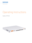
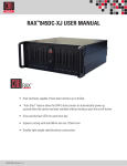
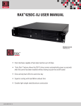
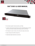
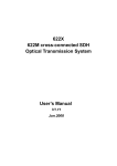
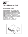
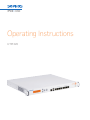
Operating Instructions
UTM 220
Foreword
We are pleased to welcome you as a new customer of our Sophos UTM
hardware appliances.
To install and configure the hardware appliance you can use the following
documents:
ÌÌ H
ardware Quick Start Guide: Connection to the system peripherals in a few
steps
ÌÌ O
perating Instructions: Notes on the security and commissioning of the
hardware appliance
ÌÌ Administration Guide: Installing and configuring the software appliance
The Hardware Quick Start Guide and the Security Notes are also delivered in
printed form together with the hardware appliance. The instructions must be
read carefully prior to using the hardware and should be kept in a safe place.
You may download all user manuals and additional documentation from the
support webpage at: astaro.com/support
Security Symbols
The following symbol and its meaning appears in the Hardware Quick Start
Guide, Security Notes and in these Operating Instructions.
Caution and Important Note. If these notes are not correctly observed:
ÌÌ This is dangerous to life and the environment
ÌÌ The appliance may be damaged
ÌÌ The functions of the appliance will be no longer guaranteed
ÌÌ S
ophos shall not be liable for damages arising from a failure to comply
with the security notes
Designed Use
The hardware appliances are developed for use in networks. The UTM 220
model may be operated as a standalone appliance. The hardware appliance
can be used in commercial, industrial and residential environments.
The UTM 220 model belongs to the appliance group A.
The hardware appliance must be installed pursuant to the current
installation notes. Otherwise failure-free and safe operation cannot be
guaranteed. The EU declaration of conformity is available at the following
address:
Astaro GmbH & Co. KG - a Sophos company
Amalienbadstr. 41/Bau 52
76227 Karlsruhe
Germany
UTM 220 Operating Instructions
CE Labeling, FCC and Approvals
The UTM 220 appliance complies with FCC Class A, CE, C-Tick, VCCI and
UL.
Important Note: For computer systems to remain CE and FCC compliant,
only CE and FCC compliant parts may be used. Maintaining CE and FCC
compliance also requires proper cable and cabling techniques.
Operating Elements and Connections
Sophos UTM 220 (rev.5)
LCD and
control keys
COM
2 x USB
8 x 10/100/1000
VGA
Base-TX ports
LED: power
hard disk
fans
LED:
power
power
switch
hard disk
Controls
Power (LED Display)
Green
Power on
Green
HDD (Hard disk access)
LEDs on each Ethernet connector
Link LED
Activity
LED
Green
Yellow
Constantly
1. The Ethernet port is receiving power.
2. Good connection between the
Ethernet port and hub.
Off
1. T
he adapter and switch are
not receiving power.
2. No connection between
both ends of network.
3. Network drivers have not been loaded
or do not function correctly.
Flashing
Off
UTM 220 Operating Instructions
The adapter is sending or receiving network
data. The frequency of the flashes varies
with the amount of traffic.
No activity
LCD and Control Keys
The Sophos UTM 220 has an LCD and an operating unit with four membrane
keys. In the LCD, 16 characters per line can be displayed. The display
contains in three cycling views information on the hardware and specific
system states.
*** Astaro ***
Security Gateway
ASG ver. 8.000
CPU i686 1001 MB
Busy 27.0%
Load 0.0
10 days 01:43:17
Load 0.0
After the security appliance has booted
this message is displayed.
Sophos UTM version
CPU type and RAM size
CPU load (bar)
OS load (bar)
Uptime
Network load (bar)
With the membrane keys three actions can be executed
ÌÌ Factory reset: All settings are reset to the factory settings. The factory
reset function sets all of the configuration settings and options to their
original state. All data entered after the initial installation will be deleted,
including the HTTP proxy cache, the entire email queue, accounting and
reporting data, passwords, and uninstalled Up2Date packages. The version
of the software will not change. That is, all firmware and pattern updates
that have been installed will be retained.
ÌÌ R
eboot machine: The security appliance is rebooted. The reboot action
will shut down the system completely and reboot.
ÌÌ S
hut down: The security appliance is shut down. The shut down action
allows you to turn off the system, and allows you to cleanly stop all
running services.
The keys have the following functions
The current menu is left. When the key is pressed a couple of times, the
modifications are discarded and the initial state will be displayed.
Those keys are used to switch between the different menus and/or
characters.
Pressing executes the configured action.
UTM 220 Operating Instructions
Starting factory reset
1. Press the Enter key.
2. Press the ▼ key.
The following message will be displayed: All data erased
3. Press the Enter key.
The following message will be displayed: Are you sure?
With the up/down keys you can select Yes (y) or No (n).
4. Press the Enter key to confirm your settings.
The factory reset action will now start.
Starting reboot machine
1. Press the Enter key.
2. Press twice on the ▼ key.
The following message will be displayed: Rebooting
3. Press the Enter key.
The following message will be displayed: Are you sure?
With the up/down keys you can select Yes (y) or No (n).
4. Press the Enter key to confirm your settings.
The reboot machine action will now start.
Starting shut down
1. Press the Enter key.
2. Press triply on the ▼ key.
The following message will be displayed: Shutting down
3. Press the Enter key.
The following message will be displayed: Are you sure?
With the up/down keys you can select Yes (y) or No (n).
4. Press the Enter key to confirm your settings.
The shut down action will now start.
Putting into Operation
Caution: Risk of explosion if battery is replaced by an incorrect type. Dispose
of used batteries according to the instructions.
Scope of Supply
The supplied parts are indicated in the Hardware Quick Start Guide.
UTM 220 Operating Instructions
Mounting Instructions
The UTM 220 appliance is designed for use in racks. Please consider the
following security tips:
Important Note: The appliance is designed for use in rack systems.
Functional reliability outside of a rack cannot be guaranteed.
Warnings and Precautions
The appliance can be operated safely if you observe the following notes and
the notes on the appliance itself.
Rack Precautions
ÌÌ Ensure that the leveling jacks on the bottom of the rack are fully extended
to the floor with the full weight of the rack resting on them.
ÌÌ In single rack installation, stabilizers should be attached to the rack.
ÌÌ In multiple rack installations, the racks should be coupled together.
ÌÌ A
lways make sure the rack is stable before extending a component from
the rack.
ÌÌ Y
ou should extend only one component at a time—extending two or more
simultaneously may cause the rack to become unstable.
General Server Precautions
ÌÌ Review the electrical and general safety precautions that came with the
components you are adding to your appliance.
ÌÌ D
etermine the placement of each component in the rack before you install
the rails.
ÌÌ Install the heaviest server components on the bottom of the rack first, and
then work up.
ÌÌ A
llow the hot plug hard drives and power supply modules to cool before
touching them.
ÌÌ A
lways keep the rack‘s front door, all panels and server components
closed when not servicing to maintain proper cooling.
UTM 220 Operating Instructions
Rack Mounting Considerations
ÌÌ Ambient operating temperature: If installed in a closed or multi-unit rack
assembly, the ambient operating temperature of the rack environment
may be greater than the ambient temperature of the room. Therefore,
you should install the equipment in an environment compatible with the
manufacturer’s maximum rated ambient temperature.
ÌÌ R
educed airflow: Equipment should be mounted into a rack with sufficient
airflow to allow cooling.
ÌÌ M
echanical loading: Equipment should be mounted into a rack so that a
hazardous condition does not arise due to uneven mechanical loading.
ÌÌ Circuit overloading: Consideration should be given to the connection
of the equipment to the power supply circuitry and the effect that any
possible overloading of circuits might have on overcurrent protection and
power supply wiring. Appropriate consideration of equipment nameplate
ratings should be used when addressing this concern.
ÌÌ R
eliable ground: Reliable grounding must be maintained at all times. To
ensure this, the rack itself should be grounded. Particular attention should
be given to power supply connections other than the direct connections to
the branch circuit (i.e., the use of power strips, etc.).
Rack Mounting Instructions
To mount the appliance to the rack you need the delivered rack-mount
brackets. There are a variety of rack units on the market, which may mean
the assembly procedure will differ slightly. You should also refer to the
installation instructions that came with the rack unit you are using.
Important Note: Make sure you use the screws supplied with the rack-mount
brackets. Using the wrong screws could damage the hardware appliance and
would invalidate your warranty. The rack model UTM 220 is not delivered
with rails. Please observe the mounting instructions for your rack.
1. Attach the rack-mount brackets to the appliance
Place the appliance on a hard, flat surface with the front panel facing you.
Attach the rack–mount brackets to the left and right side of the appliance
with the supplied screws.
Make sure the brackets are properly attached to the appliance.
UTM 220 Operating Instructions
UTM 220 Operating Instructions
2. Choose the rack location
Leave enough clearance in front of the rack so that you can open the front
door completely (~60 cm/25 inches).
eave approximately 80 cm/30 inches of clearance in the back of the rack to
L
allow for sufficient airflow and ease in servicing.
his product is for installation only in a restricted access location (no
T
capitalization) (dedicated equipment rooms, service closets and the like).
3. Slide the appliance into the rack.
4. Attach the brackets to the rack with the appropriate screws
(not included).
Connection and Configuration
How to connect the appliance is described in the Hardware Quick Start
Guide. For configuration you can follow the initial setup wizard described in
the WebAdmin Quick Start Guide or cancel it and perform a manual setup
(see the Sophos UTM Administration Guide).
Serial Console
You can connect a serial console to the COM port of the Sophos UTM
hardware appliances. You can use, for instance, the Hyperterminal terminal
program which is included with most versions of Microsoft Windows to log
on to the appliance console. Use the provided RJ45 to DB9 adapter cable to
connect the console to your hardware appliance.
The required connection settings are:
Bits per second: 38,400, Data bits: 8, Parity: N (none), Stop bits: 1. Access via
the serial console is activated by default on ttyS1. The connections of the
appliances and the respective functionality are listed in chapter "Operating
Elements and Connections."
United Kingdom Sales:
Tel: +44 (0)8447 671131
Email: [email protected]
North American Sales:
Toll Free: 1-866-866-2802
Email: [email protected]
Boston, USA | Oxford, UK
© Copyright 2012. Sophos Ltd. All rights reserved.
All trademarks are the property of their respective owners.
Sophos Operating Instructions 02.12v1.dNA
Australia & New Zealand Sales
Tel: +61 2 9409 9100
Email: [email protected]