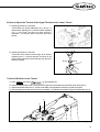
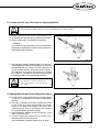
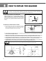
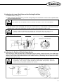
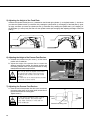
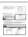
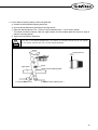
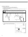
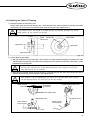
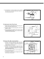
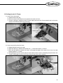
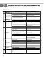
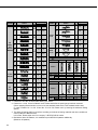
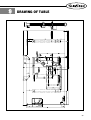
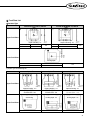
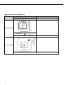
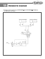
1
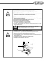
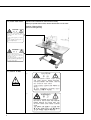
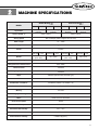
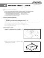
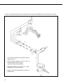
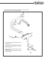
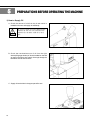
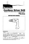
R
USER’S
MANUAL
SPS/ D-B1254 Series
SPS/ D-B1263 Series
Direct Drive, Electronically
Controlled Decorative
Pattern Tacking Machine
(Mechanical Part)
1) FOR AT MOST USE WITH EASINESS,
PLEASE CERTAINLY READ THIS MANUAL
BEFORE STARTING USE.
2) KEEP THIS MANUAL IN SAFE PLACE FOR
REFERENCE WHEN THE MACHINE BREAKS
DOWN.
SUNSTAR MACHINERY CO., LTD.
MME-051130
lity
a
u
tQ
Besst Pricevice
Be st Ser
Be
1. Thank you for purchasing our product. Based on the rich expertise and
experience accumulated in industrial sewing machine production, SUNSTAR
will manufacture industrial sewing machines, which deliver more diverse
functions, high performance, powerful operation, enhanced durability, and
more sophisticated design to meet a number of user’s needs.
2. Please read this user’s manual thoroughly before using the machine. Make
sure to properly use the machine to enjoy its full performance.
3. The specifications of the machine are subject to change, aimed to enhance
product performance, without prior notice.
4. This product is designed, manufactured, and sold as an industrial sewing
machine. It should not be used for other than industrial purpose.
R
SUNSTAR MACHINERY CO., LTD.
Organization of the Pattern Tacking S/M MODEL
SPS / D - B12
HA ⑧ Hook Type
BL : Large Shuttle Hook
① SunStar
Pattern
System
⑦ Option
② Series
TH : Upper Thread
Holding Device
D : Direct Drive Type
⑥ Feed Frame
Driven Type
③ Pattern Tacking
Model Name
54 : 50×40mm
63 : 60×30mm
④ Material Type
H : Heavy Weight Material
M : Medium Weight Material
20 : Mono Lithic Feed
Frame
22 Separately Driven
Feed Frame
⑤ Pneumatic Type
(Standard)
Contents
1. Machine Safety Regulations
6
6
6
7
7
8
8
2. Machine Specifications
9
3. Machine Structure
1) Names of Each Part of the Machine
4. Machine Installation
10
10
11
1) Machine Installation Conditions
2) Electric Installation Conditions
3) How to Install the Table
4) The Assembly of Peripheral Parts
5) Installation Method of Air Pressure Specifications
11
11
11
14
15
5. Preparations Before Operating the Machine
18
1) How to Supply Oil
2) How to Install the Needle Bar
3) How to Thread the Upper Thread
4) Threading the Lower Thread
5) How to Take the Bobbin Case On and Off
6) How to Adjust the Tension of the Upper Thread and the Lower Thread
7) How to Wind the Lower Thread
8) How to Operate a Pedal ( A-20 Type)
9) How to Operate a Pedal ( A-22 Type)
10) Disposing the Waste Oil
11) Compressed Air Input and Air Pressure Adjusting Method
12) Adjusting Method of Upper Thread Holding Device (Option)
4
6
1) Machine Transportation
2) Machine Installation
3) Machine Repair
4) Machine Operation
5) Devices for Safety
6) Caution Mark Position
7) Contents of Marks
18
19
20
20
20
21
21
22
22
22
23
23
6. How to Repair the Machine
1) Adjusting the Height of the Needle Bar
2) Adjusting the Needle and the Shuttle
3) Adjusting the Lower Shaft Gear and the Rocking Shaft Gear
4) Adjusting the Position of Shuttle Upper Spring
5) Adjusting the Height of the Feed Plate
6) Adjusting the Height of the Presser Foot Devices
7) Adjusting the Presser Foot Devices
8) Adjusting the Parts for Thread Release
9) Adjusting the Wiper Parts
10) Adjusting the Parts for Trimming
11) Adjusting the Devices for Main Thread Adjustment
12) Adjusting the Winder Devices
13) Adjusting the Hand Pulley Device
14) Mounting the Direct Motor and Adjusting Method
15) Setting Up the X-Y Origin
7. Cause of Breakdown and Troubleshooting
1) Machine Part
24
24
24
25
25
26
26
26
28
30
31
33
33
34
34
35
36
36
8. Pattern List
37
9. Drawing of Table
39
10. Gauge List
40
11. Pneumatic Diagram
43
1) Drawing of the Pneumatic Hose of SPS/D-B1254 A-20, SPS/D-B1263 A-20 Machine
(for Monolithic Feed Frame)
2) Drawing of the Pneumatic Hose of SPS/D-B1254 A-22, SPS/D-B1263 A-22 Machine
(for Separately Driven Feed Frame)
43
44
5
1
MACHINE SAFETY REGULATIONS
Safety instruction on this manual are defined as Danger, Warning and Notice.
If you do not keep the instructoins, physical injury on the human body and machine damage might be occurred.
Danger : This indication should be observed definitely. If not, danger could be happen during the installation, conveyance
and maintenance of machines.
Warning : When you keep this indication, injury from the machine can be prevented.
Notice : When you keep this indication, error on the machine can be prevented.
1-1) Machine Transportation
Danger
1-2) Machine Installation
Notice
1-3) Machine Repair
Danger
6
Those in charge of transporting the machine should know the safety regulations very
well. The following indications should be followed when the machine is being
transported.
ⓐ More than 2 people must transport the machine.
ⓑ To prevent accidents from occurring during transportion, wipe off the oil on the
machine well.
The machine may not work well or breakdown if installed in certain places, install the
machine where the following qualifications agree.
ⓐ Remove the package and wrappings starting from the top. Take special notice on the
mails on the wooden boxes.
ⓑ Dust and moisture stains and rusts the machine. Install an airconditioner and clean
the machine regularly.
ⓒ Keep the machine out of the sun.
ⓓ Leave sufficient space of more than 50㎝ behind, and on the rigth and left side of the
machine for repairing.
ⓔ EXPLOSION HAZARDS
Do not operate in explosive atmospheres. To avoid explosion, do not operate this
machine in an explosive atomsphere including a place where large quantities of
aerosol spray product are being used or where oxygen is being administered unless it
has been specifically certified for such operation.
ⓕ The machine were not provided with alocal lighting due to the feature of machine.
Therefore the illumination of the working area must be fulfilled by end user.
[Refer]Details for machine installment are described in 4. Machine Installment.
When the machine needs to be repaired, only the assigned troubleshooting engineer
educated at the company should take charge.
ⓐ Before cleaning or repairing the machine, close down the motive power and wait 4
minutes till the machine is completely out of power.
ⓑ Not any of the machine specifications or parts should be changed without consulting
the company.
Such changes may make the operation dangerous.
ⓒ Spare parts producted by the company should only be used for replacements.
ⓓ Put all the safety covers back on after the machine has been repaired.
1-4) Machine Operation
Warning
SPS/D-B1254(B1263) Series is made to sew patterns on fabrics and other similar material for
manufacturing. Follow the following indications when operating the machine.
ⓐ Read through this manual carefully and completely before operating the machine.
ⓑ Wear the proper clothes for work.
ⓒ Keep hands or other parts of the body away from the machine operation parts(needle, shuttle,
thread take-up lever, and pulley etc.) when the machine is being operated.
ⓓ Keep the covers and safety plates on the machine during operation.
ⓔ Be sure to connect the earthing conductor.
ⓕ Close down the electric motive power and check if the switch is turned“off ”before opening
electric boxes such as the control box.
ⓖ Stop the machine before threading the needle or checking after work.
ⓗ Do not step on the pedal when turning the power on.
ⓘ Do not operate the machine with any cooling fan blocked.
The air-filter on control box must be cleaned once a week.
ⓙ If possible, install the machine away from source of strong electrical noise such as high
frequency welding machines
Warning
1-5) Devices for safety
Warning
Belt will crush or amputate finger or hand, keep cover in place before
operating, turn off power before inspecting or adjusting.
Safety label : It describes cautions during operating the machine.
Thread take-up cover : It prevents from any contact between body and take-up lever.
Motor cover : It prevents from insertion of hands.feet or clothes by motor.
Label for specification of power : It describes caution for safety to protect against electric shock
during rotation the motors.
ⓔ Finger guard : It prevent from contacts between a finger and needle.
ⓕ Safety plate : It protect eyes against needle breaks.
ⓐ
ⓑ
ⓒ
ⓓ
ⓐⓑ
ⓔ
ⓒ
ⓕ
ⓓ
7
1-6) Caution Mark Position
Caution mark is attached on the machine for safety.
When you operate the machine, obesrve the directions on the mark.
Position of Warning Mark
[View from the right-front]
CAUTION
주 의
Do not operate without finger guard and
safety devices. Before threading, changing
bobbin and needle, cleaning etc. switch off
main switch.
손가락 보호대와 안전장치 없이 작동하지
마십시오.
실, 보빈, 바늘교환시나 청소전에는 반드시 주
전원의 스위치를 꺼 주십시오.
WARNING
경 고
Hazardous voltage will cause injury.
Be sure to wait at least 360 seconds before
opening this cover after turn off main switch
and unplug a power cord.
고압 전류에 의해 감전될 수 있으므로 커버를
열 때는 전원을 내리고 전원 플러그를 뽑고 나
서 360초간 기다린 후 여십시오.
1-7) Contents of Marks
Caution
1)
CAUTION
주 의
Do not operate without finger guard
and safety devices. Before threading,
changing bobbin and needle, cleaning
etc. switch off main switch.
Warning
손가락 보호대와 안전장치 없이 작동하지 마
십시오.
실, 보빈, 바늘교환시나 청소전에는 반드시
주전원의 스위치를 꺼 주십시오.
2)
WARNING
경 고
Hazardous voltage will cause injury.
Be sure to wait at least 360 seconds
before opening this cover after turn
off main switch and unplug a power
cord.
고압 전류에 의해 감전될 수 있으므로 커버
를 열 때는 전원을 내리고 전원 플러그를 뽑
고 나서 360초간 기다린 후 여십시오.
8
2
MACHINE SPECIFICATIONS
SPS/D-B1254
SPS/D-B1263
MODEL
HA
Application
Sewing Area(X, Y)
HA-BL
For Heavy Weight
Materials
MA
MA-BL
For Medium Weight
Materials
HA
HA-BL
For Heavy Weight
Materials
50mm×40mm
MA
MA-BL
For Medium Weight
Materials
60mm×30mm
Sewing Speed
Max. 2,500spm (Stitch Length is 3mm or Less)
Stitch Length
0.1∼10mm
Feeding System
Feeding by Pulse Motor
Stroke
41.2mm
Hook
Standard Large shuttle Standard Large shuttle Standard Large shuttle Standard Large shuttle
Shuttle Hook
hook
Shuttle Hook
hook
Shuttle Hook
hook
Shuttle Hook
hook
Needle
DP×17 #19
(#19∼#23)
DP×17 #19
(#19∼#23)
DP×5 #16
Lifting Amount of Feeding Frame
Max. 20mm
Lifting Amount of Presser Foot
Max. 20mm
Thread Trimmer
Standard
Emergency Stop Switch
Standard
Wiper
Standard (Electronically Solenoid Type)
No. of Stitches
Max. 10,000 Stitches
Standard No. of Patterns
56 Patterns (Pattern : 24, Bartack : 32)
Number of Patterns
Max. 99 Pattems (Standard 56 Patterns)
Memory
EP-ROM
Enlarging/Reducing
20%∼ 200% (1% Step)
Motor
Direct Drive AC Sero Motor
Power Consumption
600VA
Recommended Temperature
5°C∼40°C
Recommended Humidity
20%∼ 80%
Power
1-Phase: 100V∼240V, 3-Phases 200V∼440V, 50/60㎐
Ariborne Noise Humidity
0.49MPa (5kgf/cm²)
DP×5 #16
9
3
MACHINE STRUCTURE
1) Names of Each Part of the Machine
Motor Cover
Arm
Thread Stand
Emergency
Stop Switch
Safety Plate
Ass’y
Operation Box
Power Switch
Pedal Switch
10
4
MACHINE INSTALLATION
1) Machine Installation Conditions
A. Do not use the machine where the voltage is over regular voltage ±10% to prevent accidents
B. For safe operation of the machine, use the machine under the following conditions.
Surrounding Temperatuer During Operation : 5。~40℃ (41。F~104。F)
Surrounding Temperature During Maintenance : -10。~60℃(14。F~140。F)
C. Humidity : Between 20~80%(Relative humidity)
2) Electric Installation Conditions
A. Power Voltage
· The power voltage must be between regular voltage ±10%
· The frequency of the power should be regular frequency(50/60㎐) ±1%
B. Electromagnetic Wave Noise
Use separate power with strong magnetics of high frequency products, and do not leave the machine near them.
C. Ues low voltage when supplements or accessories are being adhered.
D. Be careful not to have water of coffee be spilled into the Controller and Motor.
E. Do not drop the Controller or Motor.
3) How to Install the Table
A. Please fix the oil tub support ①, the oil support ②, the
control box ③ and the power switch ④ on the table.
②
①
④
③
[ Fig. 1 ]
B. Attach the bed cushion rubber ① and safety switch
supporting rubber ② to the table.
①
②
[ Fig. 2 ]
11
C. Add the hinge metal and hinge rubber to the bed.
Then insert the fixing bolt into the hinge metal hole of
point ① and fix the table as shown in the picture.
Bolt
Hinge Rubber
The machine should be carried by more
2 people for safety
Danger
①
Hinge
[ Fig. 3 ]
D. Stand the machine as shown in the picture, and then fix
the machine on the table after inserting the fixing bolts
into the hinge metal holes of point ①.
①
Danger
Since the machine is not perfectly installed
on the table, extreme care is needed
when you make the machine stand up not
to have any accident occurred.
Bolt
①
[ Fig. 4 ]
E. Assemble the safety switch bracket ① on the bed as in
the figure. Move the safety switch bracket up and down to
make sure that the safety switch supporting rubber ② is
tightly pressed by the safety switch ③, and then fasten the
screw ④.
①
②
④
③
[ Fig. 5 ]
12
F. After the cable connections beween the machine and the control box is finished, fix the cable wiring under the table
as shown in the picture.
(Adjust the length of the wire considering the situation of standing the machine.)
Table
[ Fig. 6 ]
13
4) The Assembly of Peripheral Parts
A. Attach the motor cover on the back side of the machine
(4 positions) by using the 4 joint screws.
Fixing Screw
Motor Cover
[ Fig. 7 ]
B. Attach the safety plate to the left side of machine by using
fixing bolt.
Face Plate
Safety Plate
Ass’y
[ Fig. 8 ]
For safety, motor cover and safety plate should be attached to the machine.
Caution
C. Install the thread stand on the table.
[ Fig. 9 ]
14
5) Installation Method of Air Pressure Specifications
A. Assembly method of filter regulator attach to right side
of the table leg by using a bolt as shown in the figure.
[ Fig. 10 ]
B. Assembly method of solenoid valve
Fix it tightly at the proper location of the table bottom by
using the fixing screw.
[ Fig. 11 ]
15
C. How to connect the pneumatic hoses of monolithic feed frame machine (for SPS/D-B1254 A-20 / B1263 A-20 machine)
②
①
1. Connect filter regulator and solenoid valve by
using the hose ①.
①
2. Insert the hoses labelled“S3F”and“S4F”to
the A and B part as shown in figure.
(Confirm the noses are inserted filly.)
3. Using quick couplings ②, connect “S3L”&“S3R”
to S3F and“S4L”&“S4R”to S4F”
4. Finally, connect the solenoid and the connector of
pressure swith.
[ Fig. 12 ]
16
D. How to connect the pneumatic hoses of the separately driven feed frame machine
(for SPS/D-B1254 A-22 / B1263 A-22 machine)
Air Hose
Cap Net
Hose Nipple
①
1. Connect filter regulator and solenoid valve by
using the hose ①.
2. Assemble the hose with the label of“S3L, S4L,
S3R, S4R”to the attaching part of solenoid as
shown in the figure
3. Finally, connect the solenoid and the connector of
pressure switch.
(Please match the label of solenoid and connector
and connect them.)
[ Fig. 13 ]
17
5
PREPARATIONS BEFORE OPERATING THE MACHINE
1) How to Supply Oil
A. Check the amount of oil left in the oil tank which is
installed on the arm and supply oil stufficiently.
Caution
Be sure to supply oil when operating the
machine for the first time and when the
machine has not been used for a long
time.
[ Fig. 15 ]
B. Check the remained amount of oil from the right
window(Oil gauge window) of oil tank installed on the bed
as seen in the figure, then supply oil enough through the
lubrication hole on the bed cover.
[ Fig. 16 ]
C. Supply oil into the hole in the upper part of the arm.
[ Fig. 17 ]
18
D. Open the hook cover and supply oil till the shuttle race
ring is surrounded by oil. Put the hook cover back on
after finishing.
Caution
For safety, keep the hook cover
covere during operating.
Shuttle Race Ring
Hook Cover
[ Fig. 18 ]
E. Supply sillicon oil into the sillicon oil tank which is installed
on the right side of the arm.
Sillicon Tank
[ Fig. 19]
2) How to Install the Needle Bar
Unfasten the needle fixing screw on the needle bar.
Then, with the needle groove facing forward, push the
needle until the upper end touches the needle hole of the
needle bar. Fix the needle in with the needle fixing screw.
Screw
Needle
[ Fig. 20 ]
19
3) How to Thread the Upper Thread
After placing the thread take-up lever on the top position, hang the upper thread as shown in the Figure.
Concerning the thread guide of the needle bar, hang thread to use for heavy weight material as shown in Fig.① and
hang thread to use for general and thin knit material as shown in Fig. ②.
HA
(Heavy Weight Material)
MA
(Medium Material)
Fig.②
Fig.①
40mm
[ Fig. 21 ]
4) Threading the Lower Thread
A. Insert bobbin ① into bobbin case ② as shown in the
picture.
25mm
Insert the bobbin to turn clockwise when
seen from behind the bobbin case
③
Caution
②
①
B. After setting the lower thread through the crack of the
bobbin case, insert the thread through thread hole ③.
C. Adjust the lower thread to hang 25mm out of thread hole
③.
[ Fig. 22 ]
5) How to Take the Bobbin Case On and Off
Opening the hook cover, hold the knob ① of bobbin case
and push into the shuttle until sounding.
Caution
lf you start operating the machine
when bobbin case is not perfectly
installed, thread can be tangled of the
bobbin case would be protruded.
Bobbin Case
①
[ Fig. 23 ]
20
6) How to Adjust the Tension of the Upper Thread and the Lower Thread
A. Adjusting the tension of the upper
Thread When the tension adjusting nuts ③ and ④, of
thread tension adjusting unit ① and sub-tension adjusting
unit ②, are turned clockwise the upper thread is
tightened. And loosens when turned the other way
around.
②
④
①
③
[ Fig. 24 ]
B. Adjusting the tension of the lower
Thread the lower thread becomes tight when tension
adjusting screw ① is turned clockwise, as shown in the
picture. When the screw is turned the other way the lower
thread is loosened.
Strong
Weak
①
[ Fig. 25 ]
7) How to Wind the Lower Thread
A.
B.
C.
D.
Press SELECT and select
in the operation box.
Insert the thread winder basis ① attached on the upper cap of the bobbin into the thread winder drive shaft ②.
Adhere the thread winder lever ③ closely to the bobbin, and operate the machine by pressing the pedal.
After separating the thread winder lever from the bobbin, cut off thread of the bobbin using the thread winder mes ④.
②
④
Bobbin
③
①
[ Fig. 26 ]
21
8) How to Operate a Pedal (
A-20 Type)
A. After providing with the pedal switch of 2 pressing plates,
install it a proper position to work conveniently.
B. When you are pressing the right pedal the feed plate is
lowering down, and when you press it again, the feed
plate starts rising.
C. In the status that the feed plate is lowered you press the
left pedal, lt starts sewing, and when the sewing is
finished, the feed plate starts rising.
Work the Left Pedal
Work the Right Pedal
[ Fig. 27 ]
9) How to Operate a Pedal (
A-22 Type)
A. It provides with the pedal switch of 2 pressing plates.
Install it a proper position to work conveniently.
B. When you are pressing the right pedal, the right feed
plate is lowering down, and when you press it again, it
starts rising.
C. When you press a step on the left pedal, the left feed
plate starts lowering, and when you take off your foot, it
starts rising again.
D. In the status that the right feed plate is lowered you press
a step on the left pedal, the left feed plate starts lowering,
and when you press a second step, it starts sewing.
When the sewing is finished, the left and right feed plates
start rising automatically.
E. Please refer to Page 18 in the electrical and electronic
manual concerning how to change the parameters of the
separate pedal.
Work the Left Pedal
Work the Right Pedal
[ Fig. 28 ]
10) Disposing the Waste Oil
When the oil receiving oiler at the bottom of the table is full,
take it off to empty.
Caution
Spread out some fabrics of papers on
the floor when you attach or remove
the oil receiving container.
Oiler
[ Fig. 29 ]
22
11) Compressed Air Input Air Pressure Adjusting Method
Please Operate under power-off status for prevention of safety assiden.
Note
A. Please connect quick joint socket ① that pressed air was
connected to the quick joint plug ② attached to the table.
①
③
B. Open the finger valve ③ and input the pressed air.
[ Reference ]
If you close the finger valve after you use it, automatically
dischange the remained air and the remained pressure is
indicated as 0 MPa (0 kgf/cm²)
②
[ Fig. 30 ]
C. After pulling the adjusting handle located on th upper part
of filter regulator as shown in the right figure, if you turn it to
clockwise direction, the pressure rise and if you turn it to
counter clockwise direction, the pressure drops. Therefore,
after adjusting to the proper pressure 0.49∼0.54MPa
(5∼5.5kgf/cm²) indicated on the pressure gauge, press
the adjusting handle to the original location and fix it.
Note
If the air pressure drops while using is (less
than 4kgf/cm²), it shall be indicated as
“error”and operation of the machine shall
stop.[Er07]
[ Fig. 31 ]
12) Adjusting Method of Upper Thread Holding Device (Option)
A. Please confirm if upper thread holder pin cylinder knuckle
① and cap ② are located in the center of upper thread
passage.
B. If they are not located in the center, unfasten two pieces
of joint screw ④ of upper thread holder pin cylinder
bracket ③ and adjust to be located in the center. Then
unfasten two joint screw ④ and adjust to be located in
the center and fasten joint screw ④ tightly.
C. Standard distance between end of knuckle cap ② and
ARM ⑤ should be 4mm.
D. In order to adjust this, unfasten two pin cylinder nut ⑥
and adjust distance of front and back.
Then if adjustment is finished, fasten two nut ⑥ tightly.
②① ③
④
③
⑥
⑤
4mm ⑥
[ Fig. 32 ]
23
6
HOW TO REPAIR THE MACHINE
The machine is set to be the best condition at the factory. Do not make any discrete adjustments
on the machine and replace genuine parts approved by the company only.
Caution
1) Adjusting the Height of the Needle Bar
When the needle bar os at its lowest position, unfasten the
needle bar holder screw ①. Adjust the desired height by
making the specified upper carving line fit in with the needle
bar bushing. Then, tigh tenthe needle bar holder screw back
in firmly.
①
DP×5
DP×17
[ Fig. 33 ]
2) Adjusting the Needle and the Shuttle
Needle Bar
Lower Bushing
A. Have the lower carving line for the needle that is applied
when the needle bar goes up fit in with the lower side of
the needle bar bushing as shown in the picture.
DP×5
DP×17
[ Fig. 34 ]
B. After unfastening the shuttle drive screw ①, open the inner hook pressure bar ② left to right and remove the shuttle
race ring ③ from the (large) shuttle ④.
C. Make the shuttle hook point accord with the center of the needle. And make the needle and the front face of the
shuttle drive connect each other to prevent the needle from curving. Then, tighten the drive screw ① firmly.
D. After unfastening the (large) shuttle scerw ⑤, turn the large hook adjustment shaft ⑥ to the left to right and adjust
the (large) shuttle ④ so that the needle and the shuttle hook point is 0.05∼0.1mm apart from each other.
E. After adjusting the (large) shuttle ④ in place, adjust the rotary direction of the (large) shuttle ④ so the needle and
the (large) shuttle ④ is 7.5mm apart from each other. Then, tighten the (large) shuttle screw ①.
For safety, make sure all the screws are tightened firmly after adjusting the (large) shuttle.
Caution
0mm
7.5mm
②
0.05∼0.1mm
②
③
⑤⑥
④
①
[ Fig. 35 ]
24
3) Adjusting the Lower Shaft Gear and the Rocking Shaft Gear
A. Unfasten screws ① and ②, ③
B. While having the upper shaft turning, move the rocking shaft gear in the direction of the arrow to the position where
it will move easily without load.
The machine may not operate when the rocking shaft gear in not in the right position.
Caution
C. Have the oscillator shaft collar (right) stick to the bed surface
, and then tighten the collar screw.
D. Turn the oscillator shaft collar (right), still sticking to the bed surface , in the direction of the arrow and make
adjustments so the end of the shuttle drive will rotate smoothly with the backlash of under 0.1mm.
If there is too much backlash the machine may make more noise than usual during
operation. And if there is not enough backlash, the machine may not operate.
Caution
E. Tighten screw ① and ③ back on firmly.
Oscillator Shaft Collar(R)
③
Backlash 0.1mm and Below
①
②
[ Fig. 36 ]
4) Adjusting the Position of Shuttle Upper Spring
After removing the lower feed plate and the needle plate from the machine, unfasten the screw of the shuttle upper
spring. Then, adjust the shuttle upper spring so that the backside of the needle and comes to point
in the vertical
direction, and the center of the needle will come to the middle of interval
horizontally. After the adjustment is done,
tighten the screw back on firmly.
Caution
The thread may be disconnected or the thread strand may be unfastened if there are
scratched or if the surface is rough around the shuttle upper spring. Always check the
surface of the spring before operating the machine.
①
①
①
[ Fig. 37 ]
25
5) Adjusting the Height of the Feed Plate.
Unfasten the cylinder knuckle joint nut ③ attached on the left and right cylinders ② on the feed bracket ①. And when
you raise the cylinder knuckle ⑤ to direction A by rotating the cylinder shaft ④, the height(T) of the feed plate ⑥ is set
up highly, and when you lower the cylinder knuckle ⑤ to direction B by rotating the cylinder shaft ④, the height(T) of
the feed plate ⑥ is set up lowly. Be sure to fix the cylinder knuckle joint nut tightly after adjusting the height of the feed
plate ⑥.
⑤
①
T
③
A
④
S
B
②
⑥
[ Fig. 38 ]
6) Adjusting the Height of the Presser Foot Devices
A Unfasten the presser foot joint screw ① at the lowest
position of the needle bar.
B. Adjust the height of the presser foot to correct the
distance between the presser foot bottom surface and
the sewing material to be 0.5mm (the thickness of using
thread) and then fasten the joint screw.
→
→
Caution
①
Make sure to check the position of the wiper
after adjusting the height of the presser foot.
·A flipping away shall be caused by a wide
interval.
·A malfunction of the thread adjusting shall be
caused by a narrow interval
0.5mm
[ Fig. 39 ]
7) Adjusting the Presser Foot Devices
A. Have the end of the presser foot drive cam accord with
the carving point center of the upper shaft, and the line of
the cam accord with the carving point.
Tighten screw ①.
Caution
lf the presser foot drive cam is not in
the rigth position, the presser foot
may move vertically in time and run
into needle bar.
①
Carving
Point
Upper
Shaft
Presser Foot Drving Cam
[ Fig. 40 ]
26
B. Height Adjustment of Presser Bar
Adjust the presser bar that end of presser bar should
come out about 17mm from presser bar handle and
check if the needle passes through center of presser
bar.If checking ends, fasten joint screw ①.
Caution
Fasten joint screw ① of presser bar
with the pressure about 40∼45kgf/cm².
If connection pressure is excessive,
it becomes cause of deformation of
presser bar and cause trouble to
machine operation.
Presser
Bar
①
Presser
Bar Holder
Presser Foot
[ Fig. 41 ]
C. Adjustment of Presser Foot Adjusting Arm
a) Unscrew location link stopper screw to make space between location link stopper ④ and fixing stud screw of
presser foot motion link ③.
b) After unscrewing fork link joint screw ① and placing stud screw of presser foot link to the right side of presser
foot adjusting arm, fasten stud screw ② of presser foot link tightly.
c) Place the needle bar to the lowest point by turning the hand pulley.
d) Raise the presser bar so that the distance between presser bar handle and presser bar bush is to be 4mm and
fasten the joint screw ① of fork link tightly.
Caution
If there is space between presser bar handle and presser bar bush, interference and noise is
occurring during machine operation, screws are not fastened tightly after adjustment; it can cause
breakage during operation.
e) Adjust so that location link stopper ④ and fixing stud screw of presser foot motion link ③ get close by turning
stopper screw of location link.
Caution
If fixing stud screw ③ of presser foot motion link and end of the location link stopper ④
did not get perfectly close, trembling phenomenon occurs during operation and noise can
increase.
f) After fastening fork link joint screw ① tightly, check if there is play to vertical direction in presser foot adjusting
arm. Checking fastening status of screws, adjust presser foot stroke.
Presser Foot Adjusting Arm
②
①
④
③
9mm
Presser Bar Bush
Presser Bar Holder
[ Fig. 42 ]
27
D. Adjustment of Presser Foot Stoke(Adjustment of Presser
Foot UP/DOWN Motion)
After unfastening stud screw ① of presser foot adjusting
arm, placing it to A direction, presser foot stroke
increases. Placing to direction B, stroke decreases. (It is
set to 4mm at the moment of factory shipping).
B
A
①
[ Fig. 43 ]
8) Adjusting the Parts for Thread Release
A. How to Set the Thread Release Notch
Place the notch so that the right side of the slot of the
thread release notch ① touches circumference of the
notch screw ②, and then fix with a screw.
Caution
②
①
The remaining amount of thread may
not be enough or not be regular and
the thread may be unfasten from the
needle if the notch is not set in the
right position.
Thread
Trimming
Cam
[ Fig. 44 ]
B. How to Set the Thread Release Stopper
ⓐ Remove the thread release return spring.
ⓑ After unfastening the thread release stopper screw, adjust the trimming drive link and the thread release lever
pin 0.3mm apart from each other. Then, attach the arm to the thread delay stopper completely.
When the thread release stopper is pushed to the right, the space between the trimming drive link and the
thread release lever pin is reduced. And it is enlarged when the stopper is pushed to the left.
ⓒ Hang on the thread releasd return spring.
Use a tool when removing or attaching the thread delay spring to prevent accidents.
Caution
Thread Release
Lever Pin
Thread Triming
Driving Link
Return Spring
0.3mm
Widen
Narrow
Screw
Thread Rlelease
Stopper
[ Fig. 45 ]
28
C. How to adjust the opering capacity of the thread guide disk
ⓐ Unfasten the thread release adjusting plate screw.
ⓑ Open the thread guide disk by operating the trimming devices.
ⓒ Adjust the opening capacity to 0.6∼0.8mm for normal material and 0.8∼1mm for heavy material.
To increase the opening capacity, widen the angle between the thread release plate and narrow the angle to
reduce the opening capacity.
ⓓ Tighten the screw after the adjustment.
If the disk is not opened appropriately, the amount of remaining thread may be not enough
or not regular, and the disk may not be closed completely.
Caution
Widen
Floating Amount
Narrow
Upper Shaft
Screw
Thread Tension Adjusting Plate
To Tension Release Link
To Thread Tension Adjusting Ass’y
[ Fig. 46 ]
29
9) Adjusting the Wiper Parts
A.
B.
C.
D.
Unfasten the crank fixing screw ① when a needle is stopped upward.
Adjust the wiper crank ② for wiper and needle to be apart from about 40mm
Fasten the wiper crank fixing screw ①
Unfasten the wiper fixing screw ③ and adjust it for wiper tail and needle tip to be apart from about 1mm, then fasten
the wiper fixing screw ③.
If a position of wiper is not proper, the wiper can be interfered with needle or inverting
clamp devices during operating, therefore, precise operation can not be a chieved.
Caution
③
①
②
②
1mm
40mm
[ Fig. 47 ]
E. For using the wiper, press the wiper operation switch
① and for not using it, press the wiper operation
switch ①.
Wiper On/Off Switch ①
Wiper Off
Wiper On
[ Fig. 48 ]
30
10) Adjusting the Parts for Trimming
A. Setting the position of the trimming Cam
Set the upper shaft collar and the trimming cam 1.7mm apart from each other and place the trimming cam where
the trimming cam carving line accords with the upper shaft carving point. Then, tighten screw ①.
If the trimming cam is not placed in the right position, the trimming operation may not be
made correctly or the machine may be lock.
Caution
1.7mm
Carving Line
Thread
Trimmer Cam
Upper Shaft
Carving Point
Upper Shaft
Upper Shaft Collar ①
[ Fig. 49 ]
B. How to adjust the link stopper
ⓐ With the needle bar in its lowest position, check of there is enough clearance between the trimming cam roller
and both ends of the trimming cam when the trimming drive link is pushed in the direction of the arrow( ) within
the trimming cam moving part.
Caution
If there is not enough clearance between the trimming cam roller and both ends of the
trimming cam, trimming may not be operated correctly or the machine may be lock
when beginning to sew or trimming
ⓑ Make the end of the link stopper screw touch part
of the trimming link stick when the trimming cam roller is
inserted into the trimming cam moving part. Then, tighten the nut.
Thread Trimmer
Cam Roller
Thraed Trimming Driving Link
Clearance
Clearance
⇒
Caution
If the position is not set appropriately, the return to the previous point after trimming
may be delayed and the first stitch may not be tight enough.
Thread Trimmer Cam
Link Stopper Screw
Link Stopper Screw
Thread Trimmer
Connecting Bar
Thead Trimmer
Connecting Bar
Nut
[ Fig. 50 ]
31
C. Setting the trimming shaft in place
ⓐ Unfasten the trimming drive link screw and the
trimming shaft collar screw.
ⓑ Make the trimming shaft tip accord with part of the
arm.
ⓒ Tighten the screws.
Caution
Thread
Timmer Shaft
Thread
Trimmer Cam
If the position is not adjusted
appropriately, trimming may not be
operated correctly or the machine
may be lock.
Screw
Thread Trimming Collar for Thread
Driving Link Trimmer Shaft
[ Fig. 51 ]
D. Settion up the link stopper position
ⓐ Unfasten the joint screw of the thread trimmer drive
link stopper in a status the thread trimmer is not
operated. And then adjust to correct the notch
intervals between the thread driving link and the
thread driving link stopper to be 0.3mm each.
ⓑ And fasten the joint screw .
Caution
Screw
0.3mm
Thread
Trimmer
Driving
Link
An improper setting up of the
position could cause a malfunction
of the thread trimmer of a machine
sticking.
0.3mm
Thread Trimmer
Driving Link Stopper
[ Fig. 52 ]
E Setting the thread trimming solenoid in place
ⓐ After unfastening the thread trimming solenoid bracket screw, have the trimming shaft and the thread trimming
solenoid rotary link 0.5mm apart from each other and tighten the screw back on.
ⓑ Unfasten the thread trimming solenoid rotary link screw and drive the thread trimming solenoid rotary link
manually to move the trimming shaft collar 6.8mm in the direction of the arrow.Then, tighten the screw back on.
ⓒ Check if the trimming shaft collar retums to its place when the thread trimming solenoid rotary link returns.
Caution
If the position is not set right, the trimming return or the thread delay may be delayed
to bring poor sewing quality.
Screw
Thread Trimmer Solenoid Bracket
Solenoid
Screw
0.5mm
Thread Trimming
Rotation Link
6.8mm
Thread Trimming Thread Trimmer Shaft
Rotation Link
[ Fig. 53 ]
32
F. Adjusting the Moving Mes and the Fixed Mes
ⓐ When the meedle bar stops at the upper position, use the trimming lever adjustment screw to adjust space A
between the thread separation point of the moving mes and the throat plate hole as indicated in the table.
ⓑ Use the fixed mes screw to adjust space B between the fixed plate and the throat plate cover as indicated in the
table.
ⓒ after the adjustment, check the position of the mes by manual trimming operation.
Caution
Trimming may not be operated or there may not be enough remaining thread if the mes
is not set appropriately.
Needle Plate Cover
B
A
B
4.5mm
0.5mm
Moving Mes
Fixed Mes
A
[ Fig. 54 ]
11) Adjusting the Devices for MainThread Adjustment
A. When the tension control nut ① of the thread control
device is turned clockwise, the upper thread is tightened
and becomes loose as the nut is turned counter
clockwise. Adjust the tension according to the sewing
conditions such as material, thread, number of stitches
etc.
Weak
B. To tighten the take-up lever spring, use a driver to turn
the groove ② on the edge face of the thread tension
control device shaft clockwise.
And to make the spring relax, turn it counerclockwise.
Thread Take-up Spring
Strong ①
②
(Standard operating quantity 6∼8mm, and tension is
about 30∼50g.)
12) Adjusting the Winder Devices
A. To adjust the winding capacity of the bobbin, use the
beginning position of the winding control plate, an after
unfastening the screw, turn the plate in direction A for
large winding capacity and turn in direction B for small
winding capacity.
[ Fig. 55 ]
Bobbin
A
B
Bobbin Winder Adjusting Plate
[ Fig. 56 ]
33
B. After adjusting to correct the distance from the presser
foot drive cam to the thread winder drive wheel to be
1mm, fasten the joint screw.
Thread Winder
Drive Wheel
Upper Shaft
1mm
Upper Shaft front
Boothing
[ Fig. 57 ]
13) Adjusting the Hand Pulley Device
Upper Shaft
A. Tighten the screw after putting the hand pulley gear
and the hand pulley shaft tip in accord.
B. Adjust the clearance of hand pulley gears
tighten the screws.
and
Hand Pulley
Bushing
and
C. Move the bushing in the direction of the arrow to reduce
the backlash between gears and when the roller is
on the end of the pulley bushing.
Hand Pulley Shaft
Roller
[ Fig. 58 ]
14) Mounting the Direct Motor and Adjusting Method
A. When you mount the coupling on the servo motor, fit the
screw No. 1 of coupling to the flat surface of the servo
motor shaft and make the clearance between the
coupling and servo motor 0.7mm.
Screw No.1
O-Ring
Upper Shaft
B. When you mount the coupling on the upper shaft, fit the
screw No. 1 of coupling to the flat surface of the upper
shaft and make the clearance between the coupling and
upper shaft bushing(R) 2mm.
C. After mounting both couplings, check the positions of
each screws to the aligned.
※ If the positions of each screws are not aligned, the needle
does not stop normal position.
Servo Motor
Cutting Position
Upper Shaft Rear
Bushing
ARM
2 Coupling 0.7
[ Fig. 59 ]
34
15) Setting Up the X-Y Origin
A. How to set up X-axis origin
ⓐ Separate a bed cover (left).
ⓑ Move the center of work clamp foot to be placed on the center of X-axis.
ⓒ As seen in the figure, unfasten the bolts of X-sensor plate and let the end of X-sensor plate locate on the center
of sensor, then fasten the bolts with screw-driver.
Screw
X-Sensor Plate
Sensor
[ Fig. 60 ]
B. How to set up the O-point of the Y-axis
ⓐ Separate the bed cover (on the right).
ⓑ Adjust the distance ③ between the Y-transfer arm ① and the bed surface ② to 24mm.
ⓒ Move the feed bracket to position the center of the upper feed plate at the center of the Y-axis. You shall
keep the distance ③ to 24mm.
ⓓ After adjusting the end of Y-sensor plate to correct with the sensor center by unfastening the joint screw in the
Y-sensor sensing plate as shown in the Figure, fasten the joint screw using a spanner.
Sensor
Screw
②
Y-Sensor
①
Plate
③
mm
24
[ Fig. 61 ]
35
7
CAUSE OF BREAKDOWN AND TROUBLESHOOTING
1) Machine Part
No.
1
2
3
4
5
6
7
36
Condition of
Breakdown
Error on operation
or drive of machine
Bad position of
stopping position
Needle bent
Thread is cut
Stitich skipping
Errorin thread
tightening
Error in trimming
Cause of Breakdown
Troubleshooting
Loosing of belt tension and damage on belt.
Adjust the belt tension or exchange it.
Fuse shortage for main power or circuit
Check the fuse shortage of main shaft drive motor in
a controller box or exchange it
Deviation from Y and Y limit of feed bracket
Move the feed bracket to normal place
(inside limit switch)
Slackness of main drive belt
Adjsut the belt tension
Due to improper synchro position
Adjsut setting position of synchro
Damage on needle.(Bending of needle, cracks on
needle hole or groove, and, abrasion or
transformation of needle tip)
Exchange the needle
Wrong installation of needle
Install the needle properly
Contact of needle with shuttle
Adjust the distance properly between a needle and shuttle
Wrong insertion of therad
Insert the thread properly
Wrong installation of needle (Height of needle or
direction of needle tip)
Reinstall the needle
Damage on needle(Bending of needle, cracks on
needle hole of groove, and abrasion or
transformation of needle tip)
Exchange the needle.
Excessive tension of upper thread and under thread
Adjust the tension
Excessive tension and stroke of take-up lever spring
Adjust the tension and stroke of take-up lever spring
Crack on the controlling hole of shuttle surface
spring
Exchange the shuttle surface spring
Use of bending needle
Exchange the needle
Use of improper sized needle compared with using thread
Exchange the needle
Wrong installation of needle
Reinstall the needle.
Improper timing for needle and shuttle
Readjust the timing for needle and shuttle
Improper gap between groove and shuttle point
Readjust the timing for needle and shuttle
Excessive tension of take-up lever spring and stroke
Adjust the tension of take-up lever spring and stroke
Weak tension of upper thread
Readjust the tension of upper thread.
Weak tension of lower thread
Readjust the tenson of lower thread.
Improper timing for needle and shuttle
Readjust the timing for needle and shuttle
Laxity of exchanging tension between movable mes and fixed mes
Readjust the tension of fixed mes.
Abrasion and crack on blade of movable mes and fixed mes
Exchange the movable mes and fixed mes
Wrong position of trimmimg cam.
Readjust the position of trimming cam
8
No.
Pattern
PATTERN LIST
Model
Stitch
Number
B1254 75
Range of Sewing
X (mm) Y (mm)
50
No.
40
33
Pattern
Model
Stitch
Number
B1254 59
Range of Sewing
X (mm) Y (mm)
45
No.
29
34
Pattern
Model
Stitch
Number
Range of Sewing
X (mm) Y (mm)
B1254 59
30
40
35
B1263 75
60
30
B1263 59
45
25
B1263 51
30
30
B1254 139
50
30
B1254 159
50
40
B1254 155
30
35
36
38
37
B1263 153
60
30
B1263 121
45
25
B1263 145
30
30
B1254 219
50
40
B1254 229
50
40
B1254 335
45
40
41
40
39
B1263 193
60
30
B1263 223
60
30
B1263 349
60
30
B1254 397
50
40
B1254 84
30
30
B1254 147
35
40
43
42
44
B1263 373
60
30
B1263 84
30
30
B1263 133
35
30
B1254 56
33
30
B1254 56
35
35
B1254 74
36
36
46
45
47
B1263 56
33
30
B1263 48
30
30
B1263 63
38
30
B1254 78
8
35
B1254 116
31
31
B1254 109
28
28
49
48
50
B1263 70
8
30
B1263 113
30
30
B1263 109
28
28
B1254 136
28
28
B1254 122
40
28
B1254 152
34
31
51
53
52
B1263 136
28
28
B1263 122
40
28
B1263 152
32
30
B1254 142
40
24
B1254 65
30
8
B1254 65
8
30
B1263 65
8
30
54
55
B1263 142
40
24
56
B1263 65
30
8
37
Application No.
Pattern
Stitch Range of Sewing
Number X (mm) Y (mm)
1
10
Application No.
2
Stitch Range of Sewing
Number X (mm) Y (mm)
Pattern
18
28
2
16
2.5
3
10
2
4
16
5
6
19
25
0
36
25
0
2.5
21
41
25
0
10
2
22
44
35
0
16
2
31
42
11
7
7
16
2.5
32
42
11
7
8
24
3
9
56
24
3
10
64
24
3
11
21
6
2.5
42
Semi
Circle
Vertical
No.
For Thin
12
Materials
28
6
2.5
13
36
6
2.5
14
14
8
2
15
21
8
2
16
28
8
2
21
10
0
Straight 17
Line
23
24
25
26
28
4
20
36
4
20
42
4
20
56
4
20
29
30
0
20
28
0
20
Pattern
Stitch Number
Range of X (mm)
Sewing Y (mm)
Linear Vertical
No.
For
Knit
0
Straight
20
Line
36
For
Heavy
and
General
Materials
10
28
27
28
18
0
20
0
10
Pattern
Stitch Number
Range of X (mm)
Sewing Y (mm)
21
Note) 1. Pattern No. 33 to No. 56 are for label, waving, etc, works.
2. Pattern No. 1 to No. 32 are for Bartack works. Please work after the option gauge has been mounted.
(When operating Bartack works, be sure to use the standard shuttle hook or the standard bobbin case)
(In case of Pattern No. 1 to No. 32 and No. 47 to No. 56, Please use it by lowering the maximum sewing
speed.)
3. The status of sewing shall be not uniform according to the kinde of sewing materials and other conditions in
case of patterns fo Bartack works.
In this case, Please make use of our company’s SPS/C(D)-B1201 series
4. Besides the above 56 Patterns, it is available to provided with 43 patterns additionally.
(Maximum 99 patterns)
38
9
DRAWING OF TABLE
39
10
GAUGE LIST
No.
SPS/D-B1254
Name
MA(Medium)
HA(Heavy)
/ B1263
Large Hook Option(MA) Large Hook Option(HA)
1
Thread Take Up
Lever Ass’y
□
08S001P-306H
2
Link Cam
□
02-102A-120H
3
Needle Bar
□
04S001S-306H
4
Thread Guide of
Needle Bar
◇
04S008S-306G
○
04S007S-306H
◇
04S008S-306G
○
04S007S-306H
5
Needle
♧
DP×5 #16
♧
DP×17 #19
♧
DP×5 #16
♧
DP×17 #19
6
Shuttle Race Ring
♧
07-022A-120M
(Carving Point M)
♧
07-021A-120H
(Carving Point H)
7
Shuttle
♧
07-029A-120M
♧
07-028A-120H
8
Shuttle Upper Spring
9
Thread Tension
Adjusting Ass’y
♧
40S001S-306G
□
40S001S-306H
♧
40S001S-306G
□
40S001S-306H
10
Needle Plate Cover
♧
10-043A-120M
(Ø1.6)
□
10-041A-120H
(Ø2.3)
♧
10S043S-306G
♧
10S042S-306H
11
Fixed Knife
□
10-101A-120H
○
10S045S-306H
12
Moving Knife
□
10-106A-120H
○
10S047S-306H
13
Moving Knife
Shoulder Screw
□
10-048A-120H
○
10S048S-306H
NOTE)
40
:
♧ :
○ :
◇ :
□
07S027S-306H
◇
07S029S-306G
◇
07S028S-306H
□
07S040S-306G
Common Use with SPS/C(D)-B1201H Model (Heavy Weight Material)
Common Use with SPS/C(D)-B1201M Model (General Material)
Common Use with SPS/A(B)-1306HS Model (Heavy Weight Material)
Common Use with SPS/A(B)-1306GS Model (General Material)
◈ Feed Plate List
⊙ Standard Type
SPS/D-B12
HA-20, MA-20
A
SPS/D-B12
HA-22, MA-22
D
Upper Feed Plate
1ea
B1254
B1263
Depth of knurling : 0.7
22-010A-1254, 22-011A-1254
22-009A-1263, 22-010A-1263
1ea
From the screw
holes
B1254
B1263
Depth of knurling : 0.7
22-008A-1254
22-008A-1263
Lower Feed Plate
Knurling depth
B1254
B1263
22-034A-1254
22-032A-1263
1ea
Option E
Option F
Option G
⊙ Option Type for Bartacking Job
E
F
G
Upper Feed Plate
Depth of knurling : 0.5
Depth of knurling : 0.7
Depth of knurling : 0.7
22-044A-1254 : 1ea
22-045A-1254 : 1ea
22-047A-1254 : 1ea
22-048A-1254 : 1ea
22-050A-1254 : 1ea
22-051A-1254 : 1ea
with knurling
Knurling depth : 0.5
Knurling depth : 0.5
22-046A-1254 : 1ea
22-049A-1254 : 1ea
22-052A-1254 : 1ea
Lower Feed Plate
41
⊙ Special Option type for Label Attaching
HA-22, MA-22
Label option for Separately Driven Feed Frame
Upper Feed Plate
Depth of knurling : 0.7
Label Size
Sewing Area
A×B
A-5 × B-5
From the screw holes
Order Made Parts
Lower Feed Plate
with knurling
Order Made Parts
42
PNEUMATIC DIAGRAM
1) Drawing of the Pneumatic Hose of SPS/D-B1254
(for Monolithic Feed Frame)
A-20, SPS/D-B1263
S3L
S4F
S3F
S34F
A
EA
AIR IN
Presser Foot Cylinder(Left)
S4R
S3R
Presser Foot Cylinder(Right)
A-20 Machine
S4L
11
B
P EB
P
R
A
43
2) Drawing of the Pneumatic Hose of SPS/D-B1254
(for Separately Driven Feed Frame)
S34F
A
S34F
P EB
P
R
44
S4L
S3L
B
EA
AIR IN
Presser Foot Cylinder(Left)
S4R
S3R
Presser Foot Cylinder(Right)
A-22, SPS/D-B1263
A
A
EA
B
P EB
A-22 Machine