1
APPENDIX
ESPAÑOL
FRANÇAIS
ENGLISH
LCD
Projector
User Manual
S120
MODEL
LVP-S120A
1
CAUTION
RISK OF ELECTRIC SHOCK
DO NOT OPEN
CAUTION: TO REDUCE THE RISK OF ELECTRIC SHOCK,
DO NOT REMOVE COVER (OR BACK)
NO USER-SERVICEABLE PARTS INSIDE
REFER SERVICING TO QUALIFIED
SERVICE PERSONNEL.
The lightning flash with arrowhead symbol, within an equilateral triangle, is intended
to alert the user to the presence of uninsulated “dangerous voltage” within the
product’s enclosure that may be of sufficient magnitude to constitute a risk of electric
shock.
The exclamation point within an equilateral triangle is intended to alert the user to the
presence of important operating and maintenance (servicing) instructions in the literature accompanying the appliance.
WARNING:
TO PREVENT FIRE OR SHOCK HAZARD, DO NOT EXPOSE THIS APPLIANCE TO RAIN OR
MOISTURE.
CAUTION:
TO PREVENT ELECTRIC SHOCK, DO NOT USE THIS (POLARIZED) PLUG WITH AN EXTENSION CORD, RECEPTACLE OR OTHER OUTLET UNLESS THE BLADES CAN BE
FULLY INSERTED TO PREVENT BLADE EXPOSURE.
NOTE:
SINCE THIS PROJECTOR IS PLUGGABLE EQUIPMENT, THE SOCKET-OUTLET SHALL BE
INSTALLED NEAR THE EQUIPMENT AND SHALL BE EASILY ACCESSIBLE.
WARNING
Use the attached specified power-supply cord. If
you use another cord, it may cause interference
with radio and television reception.
Use the attached RGB cable, RS-232C cable with
this equipment so as to keep interference within the
limit of a Class A device.
2
The projector automatically shuts off
when the lamp is used up in about
2,000 hours, and the projector wont
turn on until lamp is replace.
DO NOT LOOK DIRECTLY INTO THE LENS
WHEN PROJECTOR IS IN THE POWER ON
MODE.
Contents
Important safeguards ...........................................................................4
Overview of the projector ......................................................................6
Overview of the remote control ............................................................8
Battery installation ............................................................................................. 9
ENGLISH
Preparing the projector for operation ............................................... 10
Basic connections ............................................................................... 12
Projector + AV equipment ................................................................................. 12
Cables and adapters .......................................................................................... 12
Projector + IBM PC or IBM PC compatibles .................................................... 13
Projector + Macintosh ........................................................................................ 14
To operate projector power ON..........................................................
Menu operation ..................................................................................
Picture adjustment .............................................................................
Advanced feature for presentation ....................................................
15
17
20
22
Expand ................................................................................................................ 22
Still ..................................................................................................................... 22
PC-CARD ............................................................................................ 23
Advanced feature with PC ................................................................. 25
PCV ..................................................................................................................... 25
Mouse remote control ........................................................................................ 31
Replaccement of a light source lamp ..................................................32
Maintenance ....................................................................................... 34
Troubleshooting .................................................................................. 35
Indicators ............................................................................................ 36
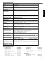
Specifications ...................................................................................... 37
Replacement parts list ....................................................................... 37
Trademark, Registered trademark
Apple, Macintosh are registered trademarks of Apple Computer Inc.
IBM, VGA, PS/2, OS/2 are trademarks or registered trademarks of International Business Machines Corporation.
Microsoft®, Windows®, Windows® 95, Windows NT® are registered trademarks of Microsoft in the U.S. and other countries.
Other brand or product names are trademarks or registered trademarks of their respective holders.
B
3
Important safeguards
PLEASE READ ALL THESE INSTRUCTIONS REGARDING YOUR LCD PROJECTOR AND RETAIN
THEM FOR FUTURE REFERENCE. FOLLOW ALL
WARNINGS AND INSTRUCTIONS MARKED ON
THE LCD PROJECTOR.
10.
Power sources
This projector should be operated only from the
type of power source indicated on the marking
label. If you are not sure of the type of power,
please consult your appliance dealer or local
power company.
1.
Read instructions
All the safety and operating instructions should
be read before the appliance is operated.
11.
2.
Retain instructions
The safety and operating instructions should be
retained for future reference.
Power-cord protection
Power-supply cords should be routed so that they
are not likely to be walked on or pinched by items
placed upon or against them. Pay particular attention to cords at plugs, convenience receptacles,
and points where they exit from the appliance.
3.
Warnings
All warnings on the appliance and in the operating instructions should be adhered to.
12.
Overloading
Do not overload wall outlets and extension cords
as this can result in a fire or electric shock.
4.
Instructions
All operating instructions must be followed.
13.
5.
Cleaning
Unplug this projector from the wall outlet before cleaning it. Do not use liquid aerosol cleaners. Use a damp soft cloth for cleaning.
Objects and liquids
Never push objects of any kind through openings of this projector as they may touch dangerous voltage points or short-out parts that could
result in a fire or electric shock. Never spill liquid of any kind on the projector.
6.
Attachments and equipment
Never add any attachments and/or equipment
without the approval of the manufacturer as
such additions may result in the risk of fire, electric shock or other personal injury.
14.
Servicing
Do not attempt to service this projector yourself.
Refer all servicing to qualified service personnel.
15.
Damage requiring service
Unplug this projector from the wall outlet and
refer servicing to qualified service personnel under the following conditions:
(a)
If the power-supply cord or plug is damaged.
(b)
If liquid has been spilled, or objects have
fallen into the projector.
(c)
If the projector does not operate normally
after you follow the operating instructions.
Adjust only those controls that are covered
by the operating instructions. An improper
adjustment of other controls may result
in damage and may often require extensive work by a qualified technician to restore the projector to its normal operation.
(d)
If the projector has been exposed to rain
or water.
(e)
If the projector has been dropped or the
cabinet has been damaged.
(f)
If the projector exhibits a distinct change
in performance - this indicates a need for
service.
16.
Replacement parts
When replacement parts are required, be sure
that the service technician has used replacement
parts specified by the manufacturer or parts
having the same characteristics as the original
part. Unauthorized substitutions may result in
fire, electric shock or other hazards.
17.
Safety check
Upon completion of any service or repair to this
projector, ask the service technician to perform
safety checks determining that the projector is
in a safe operating condition.
7.
Water and moisture
Do not use this projector near water or in contact with water.
8.
Accessories
Do not place this projector on an unstable cart,
stand, tripod, bracket or table. Use only with a
cart, stand, tripod bracket, or table recommended
by the manufacturer or sold with the projector.
Any mounting of the appliance should follow the
manufacturer's instructions and should use a
mounting accessory recommended by the manufacturer.
An appliance and cart combination should be
moved with care. Quick stops, excessive force and
uneven surfaces may cause the appliance and
cart combination to overturn.
9.
4
Ventilation
Slots and openings in the cabinet are provided
for ventilation, ensuring reliable operation of the
projector and to protect it from overheating. Do
not block these openings or allow them to be
blocked by placing the projector on a bed, sofa,
rug, or bookcase. Ensure that there is adequate
ventilation and that the manufacturer's instructions have been adhered to.
Do not operate if smoke, strange noise or odor comes
out of your projector. It might cause fire or electric
shock. In this case, unplug immediately and contact
your dealer.
Never remove the cabinet.
This projector contains high voltage circuitry. An
inadvertent contact may result in an electric shock.
Except as specifically explained in the Owner's
Guide, do not attempt to service this product
yourself. Please contact your dealer when you want
to fix, adjust or inspect the projector.
Do not modify this equipment.
It can lead to fire or electric shock.
If you break or drop the cabinet.
Do not keep using this equipment if you break or
drop it. Unplug the projector and contact your dealer
for inspection. It may lead to fire if you keep using
the equipment.
Do not face a lens to the sun.
It can lead to fire.
Use correct voltage.
If you use incorrect voltage, it can lead to fire.
Do not place the projector on uneven
surface. Level stable surface only.
Please do not place equipment on unstable surfaces.
Do not look into the lens when it is operating. It may
hurt your eyes.
Never let children look into the lens when it is on.
Do not turn off the main power
abruptly or unplug the projector
during operation.
It can lead to lamp breakage, fire, electric shock or
other trouble.
Place of installation
For safety sake, refrain from setting the projector at any
place subjected to high temperature and high humidity.
Please maintain an operating temperature, humidity, and
altitude as specified below.
• Operating temperature: between +41°F (+5°C) and
+95°F (+35°C)
• Operating humidity: between 30 and 90%
• Never put any heat-producing device under the projector so that the projector does not overheat.
• Do not attach the projector to a place that is unstable or subject to vibration.
• Do not install the projector near any equipment that
produces a strong magnetic field. Also refrain from
installing near the projector any cable carrying a
large current.
• Place the projector on a solid, vibration free surface: otherwise it may fall, causing serious injury
to a child or adult, and serious damage to the product.
• Do not stand the projector: it may fall, causing serious injury and damage to the projector.
• Place the projector within a slope of ±15˚. Slanting
the projector more than ±15˚ may cause trouble or
explosion of the lamp.
• Do not place the projector near air-conditioning unit
or heater to avoid hot air to the exhaust and ventilation hole of the projector.
COMPLIANCE NOTICE OF FCC
This equipment has been tested and found to comply with the limits for a Class A digital device, pursuant to Part 15 of the FCC Rules. These limits are designed to provide reasonable protection against
harmful interference when the equipment is operated in a commercial environment. This equipment
generates, uses, and can radiate radio frequency energy and, if not installed and used in accordance
with the instruction manual, may cause harmful interference to radio communications. Operation of
this equipment in a residential area is likely to cause harmful interference in which case the user will
be required to correct the interference at his own expense.
This digital apparatus does not exceed the Class A limits for radio noise emissions from digital apparatus as set out in the interference-causing equipment standard entitled “Digital Apparatus”, ICES-003 of
the Department of Communications.
Changes or modifications not expressly approved by Mitsubishi could void the user's authority to operate this equipment.
COMPLIANCE NOTICE OF INDUSTRY CANADA
This Class [A] digital apparatus meets all requirements of the Canadian Interference-Causing Equipment Regulations.
5
ENGLISH
WARNING:
Unplug immediately if there is
something wrong with your projector.
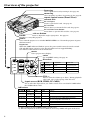
Overview of the projector
focus ring
Use to adjust the focus by turning it. See page 16.
zoom ring
Use to magnify (or reduce) by turning it. See page 16.
remote control sensor (Front / Rear)
exhaust slits
PC card eject
Press to eject the PC card. See page 23.
PC card slot
This is where you insert the PC card. See page 23.
PC card slot cover button
Press down to open the PC card slot. See page 23.
release button
Press to adjust the angle of projection. See page 11.
handle
Hold here to carry this projector.
power
Use to turn the projector on or off when MAIN POWER is on. To turn the projector off, press
this button twice.
Important:
When the LAMP indicator blinks in green, the power switch cannot be used to switch
ON and OFF. Begin operation only after the indicator has stopped blinking.
See indicator table below for more information.
menu
Use to project menu display.
enter
Use for MENU setting. See page 17.
LAMP
direction
MENU
SOURCE
Normal
RGB
ENTER
TEMP
VIDEO
CARD
PC CARD
On Menu
On PC card
Adjust FINE (-)
Set item
Select previous image (Left)
Adjust FINE (+)
Set item
Select next image (Right)
—
Select item (up)
Select INDEX or FILE
—
Select item (down)
Select INDEX or FILE
VOL
VOL +, -
Press to turn the volume up or down. During playback
of PC card, use to select group of the PC card.
input source (RGB, VIDEO, PC CARD)
Use to select the input source you wish to watch. You can select PC CARD when
the CARD indicator ON.
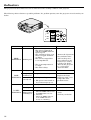
indicators
POWER( )
LAMP
TEMP
Steady red
Steady green Brinking green
} Steady green
Steady green Steady green Blinking red
Steady red
Steady red
Steady green Blinking red /green
Steady red Steady red
Steady green Steady green
CARD
Condition
Stand-by.
Power is ON.
Abnormal temperature warning (high temperature).*1
Abnormal temperature-OVER (high temperature).
The source lamp will be also turned off.
Lamp duration warning. (Lightning duration total about 1,500 hours.) *2
Lamp duration-OVER. (Lightning duration total about 2,000 hours.)
Steady green PC card inserted, off then no PC card.
*1 : In the condition, the sign of TEMP!! blinks red on the screen.
*2 : When the lamp has been used for about 1,900 hours, the message LAMP!! will appear on the screen.
6
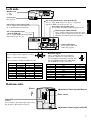
MAIN power
RGB-OUT
LINE-OUT
I : ON
O : OFF
RGB-IN
S-VIDEO
LINE-IN
VIDEO
INPUT
RS-232C
Left side
L-AUDIO-R
(MONO)
PC analog RGB input (mini D-SUB 15P)
Use to input RGB signal for PC or component
signal for DVD etc. See pages 12 - 14.
line input (stereo mini jack)
Use to input PC audio signals. See pages 13, 14.
line output (stereo mini jack)
Use to output PC audio if PC line
in, or Audio input is connected.
RGB-OUT
LINE-OUT
RGB-IN
S-VIDEO
11
PC analog RGB input
Use to input video signals (analog
RGB) of a personal computer.
(Pin assignment of Mini D-SUB 15P jack)
SPEC
R(RED)/C R
G(GREEN)/Y
B(BLUE)/C B
GROUND
GROUND
GROUND
GROUND
GROUND
PIN NO.
9
10
11
12
13
14
15
VIDEO
INPUT
video/audio input
Use to input video and
audio. See page 12.
L-AUDIO-R
(MONO)
15
RS-232C input
1
PIN NO.
1
2
3
4
5
6
7
8
LINE-IN
RS-232C
RS-232 input (Mini DIN 8P)
Use to connect with personal computer when
using the remote control as mouse, or control
the projector with the personal computer.
PC analog RGB output
(mini D-SUB 15P)
Use to output RGB signal from RGB
input. See pages 12 - 14.
SPEC
–
GROUND
GROUND
–
HD/CS
VD
–
ENGLISH
power jack
See page 11.
5
21
Use to control the projector with the
personal computer, or control the personal computer with remote control. Use
the provided RS-232C cable (Mini DIN
8P– D-SUB 9P) for the connection.
5
3
6 8
PIN NO.
NAME
I/O
1
2
3
4
5
6
7
8
TXD
RTS
DTR
GND
CTS/5V
DCD/CLOCK
RXD
RI/DATA
IN
IN
IN
–
IN/OUT
OUT
OUT
OUT
Bottom side
Front
adjustment foot (up and down)
filter cover
lamp lid
Caution:
Do not replace the lamp right after using
the projector. The lamp is very hot.
adjustment foot (right and left)
7
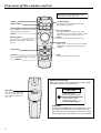
Overview of the remote control
The buttons with *mark work as same
as the buttons on the projector.
POWER
* power
card auto play
RGB
VIDEO
PC CARD
AUTO
POSITION
RELEASE
AUTOPLAY
* input source
Press to start auto play function of the
PC CARD. See page 24.
auto position
Use to adjust the position of Personal
computer image. See page 16.
* menu
PC card release
MENU
LASER
Press this button to be able to eject PC
card. Make sure to press this button all the
time to eject the PC card. See page 23.
mouse pointer
laser
Use to move the cursor on the image,
instead of the computer mouse. See
page 31.
Pressing the button emits laser beam.
right click
R-CLICK
This operates in the same way as the right
button on the computer mouse. See page 31.
* enter
* direction
ENTER
EXPAND
expand
Use to expand the image. See page 22.
STILL
VOLUME
still
Use to freeze the image. See page 22.
* +, - (volume)
About laser beam
This remote control is the class 2 (max. output 1mW
laser diode 645nm) laser equipment.
left click
This operates in the same
way as the left button on
the computer mouse. See
page 31.
CAUTION
LASER RADIATION
DO NOT STARE INTO BEAM
WAVE LENGTH : 645nm
MAX OUTPUT : 1mW
CLASS II LASER PRODUCT
CAUTION :
Pressing the LASER button provided remote control emits laser beam. Do not look into the beam
light directly. Do not point the laser beam to people.
Looking the laser beam directly may lose eyesight.
8
Battery installation
Use two AA size batteries.
1. Remove the back cover of the remote control by pushing the battery compartment door in the direction of the
arrow.
2. Load the batteries making sure that they are positioned correctly (+ to +, and - to -).
3. Replace the back cover.
2
3
ENGLISH
1
Important:
• Do not use a new battery with an old one.
• Load batteries in the correct position.
• Do not heat, take apart, or throw batteries into fire.
• Do not try to recharge batteries. Do not use rechargeable batteries.
• If the alkaline solution of alkaline batteries comes in contact with your skin or clothes, rinse with water. If
the solution comes in contact with your eyes, rinse them with water and then consult your doctor.
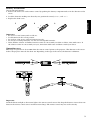
Operation area
The range for operation is about 10m when the remote control points to the projector. The distance to the screen
back to the projector must be less than 7m. Depending on the type of the screen, the distance is different.
30˚
20˚
20˚
15˚
15˚
30˚
20˚
20˚
Important:
Avoid the direct sunlight or fluorescent light to the remote control sensor. Also keep the distance of more than 2 m
between the remote control sensor and fluorescent lamp. The remote control may not work correctly.
9
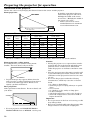
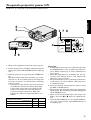
Preparing the projector for operation
Orientation of the projector
Picture size can be set by changing the distance between the screen and the projector.
Front projection
To find the approximate distance
screen
between the projector and screen:
Multiply the width of the screen
✕ 2.0 (max.) , Multiply the width of
the screen ✕ 2.5 (min.).
• Refer to the chart to recommended distances in maximum
zoom and minimum zoom.
the screen and head of
L (between
the projector)
Screen
Diagonal size
(inch)
23 "
40 "
60 "
80 "
100 "
150 "
200 "
245 "
Height inches
(inch)
13.8 "
24 "
36 "
48 "
60 "
90 "
120 "
147 "
Width feet
(inch)
18.4 "
32 "
48 "
64 "
80 "
120 "
160 "
196 "
Distance from screen (L) / (approximate)
Maximum
Minimum
zoom (min.)
zoom (max.)
(cm)
(inch)
(cm)
(inch)
112
44.1 "
–
–
201
79.1 "
155
61.0 "
305
120 "
236
92.9 "
410
161 "
317
125 "
513
202 "
399
157 "
774
305 "
602
237 "
1034
407 "
805
317 "
–
–
988
389 "
• The above numbers are the design numbers, and may be slightly different from the actual numbers.
Front projection, ceiling mount
For ceiling mount, you need the ceiling mount
bracket. For more detail, ask your dealer.
SCREEN
• Projected images may appear darker when the
unit is used as a ceiling installation than when it
is used in the tabletop position. This does not
signify a product malfunction.
Rear projection
Ask a specialist for installation. For more detail, ask
your dealer.
SCREEN
Caution:
• Placing the projector on a carpet reduces ventilation from the fan on the bottom and might cause
problems. Place a hard board or similar item
under the projector to facilitate ventilation of the
unit.
• Place the projector more than 20 in. from the wall
to prevent blocking the intake, exhaust slots and
ventilation of this projector because hot air comes
out of it.
• Do not use the projector under the following
circumstances, which may cause fire or electric
shock.
• in a dusty or humid place
• while the projector is lying sideways or upside
down.
• near a heater
• in a kitchen or oily, smoky or damp place
• in direct sunlight
• with high temperature, such as the closed car
• where the temperature is lower than 41°F or
higher than 95°F
Important:
• Do not put stress on the lens or focus ring, as this
may damage them.
• Keep your room dark while using the projector. The
image cannot be seen clearly in a bright place.
• For rear projection, set IMAGE REVERSE in
INSTALLATION menu to MIRROR. See Page 18.
10
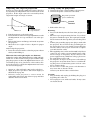
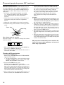
Adjusting the angle of projection
Getting ready for projection
Screen on a flat wall with a 90 degree angle to the floor
by adjusting two Adjustment feet on the bottom of the
projector. If the angle cannot be corrected by them,
adjust the height and angle of screen.
1. Connect the power cord provided to the projector.
2. Connect the power cord to the wall outlet.
ground
terminal
3. Take off the lens cap.
screen
Adjustment foot
(up and down)
1. Lift the projector to the right angle.
2. Press the release button for angle adjustment to take
the Adjustment foot (up and down) out of the projector.
3. Release the button and keep your hands away from
the projector.
4. Turn the foot to right or left to adjust for proper
angle.
After using the projection,
5. Press the release button to take the projector down
slowly with holding it.
When the left and right angles are different
Adjust the angles with adjustment feet (right and left),
which are on the bottom of the projector. When shipping the projector at first, the Adjustment feet are covered with sponge to be parallel on a flat surface. Remove the sponge to adjust the Adjustment feet lower.
Do not lose the sponge.
• Screen on a flat wall with a 90˚ angle to the floor.
• Align projector to produce a full screen display as
illustrated on page 10.
• Distance from projector to screen must be
compatible with screen size chart on page 10. Note
distance from screen chart.
Warning:
• Do not look directly into the lens when projector is
“ON”.
• The lens cap is for protecting the lens. If you leave
the power on with the cap on, the cap may be warped.
Please remove the lens cap when you turn the power
on.
• A three-pin grounding type power plug is used with
the projector. Do not remove the grounding pin on
the power plug. If you are unable to insert the plug
into the outlet, contact your electrician to replace
your A/C obsolete outlet.
• The supplied power cord is used for 120V only. Never
connect to any outlet or power supply having a different voltage or frequency. If you connect to the
power supply having a different voltage, please use
the appropriate power cord.
• Do not place an object on the power cord and keep
the projector away from heat source to avoid breaking the power cord. A broken power cord can cause
fire or electric shock.
• Do not revise or alter the power cord otherwise it
may cause fire or electric shock.
Contact your dealer if the cord is broken.
Caution:
• Plug in firmly and unplug by holding the plug, not
by pulling the cable out.
• Do not plug in or out with wet hands. It may cause
an electric shock.
11
ENGLISH
Plug in the provided
power cord directly.
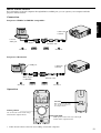
Basic connections
This projector can be connected to equipment such as VCRs, video cameras, videodisc players, and personal computers having analog RGB input.
Important:
• Make sure that your equipment is turned off before connection.
• Match the color of video and audio plugs on the AV cable with each terminal.
• Plug in firmly and unplug by holding the plug, not by pulling the cable out.
• If connected units are set too close to one another, the image may be affected.
• Refer to the owner's guide of each component for details of connections.
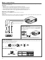
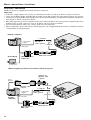
Projector + AV equipment
Make sure that your equipment is turned off before connection.
Important:
S-video signals take priority over video signals. If you input both S-video signals and normal video signals at the
same time, the normal video input automatically is inhibited.
to audio input
to S-video
input
to video input
Connect either one of these.
Projector + DVD player
Some DVD players have output terminal for 3 line fitting (Y, CB,
CR). When connecting them to the projector, connect to RGB IN
of the projector. In this case, set “Y, CB, CR” for RGB INPUT setting in SIGNAL menu.
DVD player
CB
Y
to audio to S-video to video
output
output output
G
CR
B
No connection
to RGB IN
VD
HD/CS
R
VCR, others
• Use mini D-SUB 15 pin-BNC conversion cable for connection.
• Some DVD player may not project the image correctly.
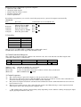
Cables and adapters
To connect personal computers to this projector, the following cables and adapters are necessary. The overview
might be different from the picture below.
RGB cable for PC (mini D-SUB 15P plug)
PIN NO.
1
2
3
MINI D-SUB 15P
Note:
PIN NO.
1
2
3
•
•
•
•
•
•
13
14
15
13
14
15
MINI D-SUB 15P
The pins numbered 9, 12 and 15 are not connected.
MAC adapter for RGB cable
(mini D-SUB 15P plug - D-SUB 15P plug)
Note: Set the dip switch to the appropriate position.
ON
1
2
3
4
5
6
DIP
%
MINI D-SUB 15P
12
D-SUB15P
Display
mode
13 inch
16 inch
19 inch
21 inch
Resolution
640 ✕ 480
832 ✕ 624
1024 ✕ 768
1152 ✕ 870
1
ON
OFF
OFF
ON
Dip switch
2 3 4 5
ON OFF OFF OFF
ON OFF ON OFF
ON ON OFF OFF
ON ON ON OFF
6
OFF
OFF
OFF
OFF
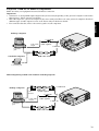
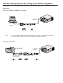
Projector + IBM PC or IBM PC compatibles
Make sure that your equipment is turned off before connection.
ENGLISH
Important:
• Connectors or analog RGB output adapters may be necessary depending on the personal computer connected to
this projector. Please contact your dealer.
• The audio input for a personal computer is the stereo mini-jack. There are some personal computers that have
different types of audio outputs or none at all. Please ask your dealer for details.
• For connection details, refer to the owner's guide of each component.
desktop computer
to LINE IN
to PC audio
output
PC audio
cable (option)
to RGB IN
to monitor
port
notebook computer
RGB cable for PC
to monitor port
When outputting to both a PC monitor and the projector
to RGB OUT
desktop computer
to PC
monitor
to PC audio
output
RGB cable
for PC (option)
to LINE IN
PC audio
cable (option)
to RGB IN
to monitor
port
RGB cable for PC
13
Basic connections (continue)
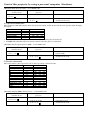
Projector + Macintosh
Make sure that your equipment is turned off before connection.
Important:
• A monitor output adapter is necessary for a Macintosh if it has no video port. Please contact your dealer.
• If you use the MAC adapter for RGB cable provided, set the dip switch to the appropriate position. See page 12.
• Connectors or analog RGB output adapters may be necessary depending on the personal computer connected to
this projector. Please contact your dealer.
• The audio input for a personal computer is the stereo mini jack. There are some personal computers that have
different types of audio outputs or none at all. Please ask your dealer for details.
• For connection details, refer to the owner's guide for each component.
• When outputting to both a PC monitor and the projector, use an Apple Macintosh monitor or multiscan monitor
corresponding to Composite Sync.
desktop computer
to LINE IN
to PC audio
output
PC audio
cable (option)
to RGB IN
ON
Power Book
6
1
2
3
4
5
DIP
to video port
MAC adapter for
RGB cable
RGB cable for PC
to video port
When outputting to both a PC monitor and the projector
Adapter for
Monitor cable
(option)
to PC
monitor
Monitor cable
(option)
to PC audio
output
to LINE IN
PC audio
cable (option)
to RGB IN
ON
1
2
3
4
5
6
to video port
DIP
desktop
computer
to RGB OUT
MAC adapter for
RGB cable
14
RGB cable for PC
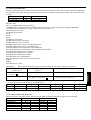
To operate projector power ON
6
5
ENGLISH
Numbers 1 - 9 correspond to the instruction numbers below.
3 7 8
RGB-OUT
LINE-OUT
RGB-IN
S-VIDEO
LINE-IN
VIDEO
INPUT
RS-232C
SOURCE
4
L-AUDIO-R
(MONO)
LAMP
RGB
TEMP
VIDEO
CARD
PC CARD
MENU
ENTER
VOL
2 9
1. Turn on the equipment connected to the projector.
2. Put the projector into standby mode by pressing the
main power switch. The POWER indicator lights up
red.
3. Turn the projector on by pressing the POWER button.
The light source lamp starts warming up, eventually turn on. In cases where light source lamp does
not come on, wait for one minute before switching
power on again.
• If the main power switch to the unit is turned
off within two minutes of turning off the light
source lamp, power will not be applied to the
lamp for one minute the next time the main
unit power switch is turned on. When this
happens, the indicator lamp will blink for one
minute.
condition
indicator
LAMP POWER
stand-by
green
when light source lamp is on
when light source lamp does not light up
-
red
green
red
Important:
• A darkened image may be seen right after pressing
the POWER button due to warming up of this projector. While warming up, no other commands can
be accepted.
• When the lamp indicator is blinking red, the service life of the lamp is about to end. Replace the
lamp. See pages 32 and 36.
• The picture might not be of optimum performance
in extreme hot or cold conditions. (The projector is
not malfunctioning.)
4. Select the desired external input source by using
the RGB or VIDEO button.
• The projector automatically selects the appropriate
signal format. The selected signal format is displayed
on the SIGNAL menu.
• When selecting the RGB input, the image may
flicker. Press the $ or % button to adjust the image.
• Press the PC CARD button to see the PC CARD images. (You cannot select it when CARD indicator is
not lighting up.)
15
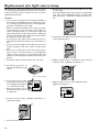
To operate projector power ON (continue)
AUTO POSITION button
When the source is selected to RGB and the image is
not in the right place, set to display as blight signal
as possible, then press the AUTO POSITION button
on the remote control. If the image is still not in the
right place.
• Set screen to the brightest display as possible
(e.g., full-screen display of the “Trash” window)
before deploying the automatic adjustment
function.
• If the screen saver is running, turn off the screen
saver before using the automatic adjustment
button.
5. Adjust the focus with the focus ring by turning it.
6. Adjust the image size with the zoom ring by turning it.
focus ring
zoom ring
tele
wide
near
far
The volume from the speaker
Press the volume + or – button to change the volume
from the speaker.
30
• The volume buttons do not work when MENU selection bar or MENU is displayed.
• The volume buttons do not work when the source is
selected to PC CARD.
Turning off the projector
7. Press the POWER button.
The message “POWER OFF? YES : PRESS AGAIN”
appears on the screen.
• To exit from this mode, press any button except
POWER, LASER, mouse pointer, R/L-click,
STILL and VOLUME + and - button.
8. Press the POWER button again.
The light source lamp will be turned off.
Pressing the POWER button again will shut off the
light source lamp, but the exhaust fan continues to
operate for 120 seconds to cool down the light source
lamp and LCD panels. In this time, the lamp indicator will be turned off from flashing.
9. Turn off the main power switch. When turning off
the main switch, the POWER indicator turns off.
16
• In cases where the main power switch is accidentally turned off when either the intake/exhaust
fan or the power source lamp is in operation, allow
the unit to cool down for 10 minutes with the
power turned off. Repeat step 3 when turning on
the power source lamp. If the lamp does not turn
on immediately, repeat this step two or three
times. Replace the lamp if it should still fail to
turn on.
Caution:
• When you have finished using this equipment, wait
120 seconds for the exhaust fans to stop. Then turn
off the main switch and unplug the power cable from
the wall outlet, for safety purposes.
• After the lamp is turned off, the lamp cannot be
switched on again for 60 seconds as a precautionary measure. It will take another 60 seconds before
the lamp indicator goes off. If you wish to turn on
the projector again, wait until the indicator is off
then press the POWER button.
• The exhaust fan runs rotate faster automatically
when the temperature around the projector becomes
high.
• When the temperature around the projector becomes
much higher, the sign of “TEMP!!” blinks red on the
screen. If the temperature stays in high, the lamp will
be shut off automatically .
The projector automatically shuts off when the
lamp is used up in about 2,000 hours and not used
until lamp replacement.
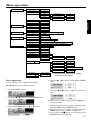
Menu operation
PICTURE
CONTRAST
BRIGHTNESS
COLOR TEMP
± 10
± 10
STANDARD
HIGH
LOW
USER
CONTRAST R
CONTRAST B
BRIGHTNESS R
BRIGHTNESS B
± 10
± 10
± 10
± 10
± 10
± 10
± 10
PRESENTATION
ZOOM MODE
POSITION
AUTO SLIDE TIME
REPEAT
1-4
1-4
3 - 99sec
ON/OFF
INSTALLATION
IMAGE REVERSE
AUTO POWER ON
TEST SIGNAL
OFF/MIRROR/INVERT/MIRROR INVERT
ON/OFF
OFF/1 - 4
OPTION
SXGA PICTURE
MENU POSITION
AUTO POWER OFF
VIDEO SIGNAL
LANGUAGE
MOTION/STILL
UPPER LEFT/LOWER RIGHT
OFF/5/10/15/30/60min.
AUTO/NTSC/PAL/SECAM/4.43NTSC/PAL-M/PAL-N/PAL-60
/English/Español/Deutsch/Français/Italiano/
SIGNAL
AUTO
HORIZ.POSITION
VERT.POSITION
FYNE SYNC.
TRACKING
RGB INPUT
HOLD
ENGLISH
TINT
COLOR
SHARPNESS
AUTO/USER1/USER2
0 - 999
*
0 - 999
*
0 - 32
0 - 9999
*
RGB/YCBCR,YPBPR
ON
OFF
AUTO
BEGIN
END
CLAMP POSITION
CLAMP WIDTH
HORIZ.PIXELS
VERT.LINES
PLL
VERT.SYNC.
SQUEEZE
USER
MEMORIZE
DELETE
RESET
USER1/USER2
USER1/USER2
Basic operation
Several settings can be adjusted using Menu.
-1 - -99
1 - 99
*
*
0 - 63
*
0 - 63
*
0 - 9999
*
0 - 9999
*
AUTO/FAST/NORMAL/SLOW
AUTO/ON/OFF
ON/OFF
* : Setting range is different according
to the type of the signal.
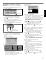
4. Press the{ or } button to select AUTO POWER
OFF.
EXAMPLE: Auto power off time setting
1. Press the MENU button.
5. Press the $ or % button to adjust auto power off
time.
2. Press the $ or % button to select OPTION menu.
6. Exit the menu system by pressing the MENU button several times.
3. Press the ENTER button (or { or } button).
• If the menu operation is not working, simultaneously
press the MENU and POWER buttons.
• The input source can not be changed when the
MENU selection bar or MENU is displayed.
• The settings with 2 mark, you should press the
ENTER button after selecting.
17
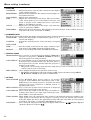
Menu setting (continue)
1 PICTURE
CONTRAST ........ Adjusts the picture contrast. The contrast becomes higher
as the number increases.
BRIGHTNESS .... Adjusts image brightness. The image becomes brighter as
the number increases.
COLOR TEMP .... Adjusts color temperature.
TINT .................... Adjusts the color balance in the image. The color balance
of the image shifts green as the number increases and
shifts to purple as the number decreases (only when
NTSC or 4.43 NTSC is selected).
COLOR ................ Adjusts the color intensity of the image (only when the
source is selected to VIDEO).
SHARPNESS ...... Adjusts the picture sharpness. The sharpness becomes sharper as the number increases
(only when the source is selected to VIDEO).
2 PRESENTATION
This menu appears when either the display enlargement and PC card play functions are used.
ZOOM MODE ..... Selects the desired type of expand mode, type1, 2, 3 or 4
(Actual size display).
POSITION .......... Selects the desired position of the sub image in expand
mode.
AUTO SLIDE
TIME ................... Sets the length of time before the image switches to the
next image in PC CARD automatic playback mode.
REPEAT .............. Sets to repeatedly playback the PC CARD presentation.
3 INSTALLATION
IMAGE REVERSE Use to reverse or invert the projected image. MIRROR is
used for rear projection. MIRROR INVERT is effective
when the projector is ceiling-mounted.
AUTO POWER ON .... To select whether to boot up automatically when the power
is turned on by a breaker. In this case, the main power of
the projector has to be ON. Set this when the projector is
hanging on the ceiling.
• The projector is in stand-by mode when the lamp does not come on. In this case, use the
remote control to turn on the lamp.
TEST SIGNAL .... Use to display the built-in test patterns on the screen.
• The display will disappear when the setting is OFF or press the button except MENU,
{ ,}, STILL, LASER, mouse pointer and R/L-click.
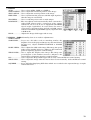
4 OPTION
SXGA PICTURE . Select MOTION when motion images are mainly
projected. Select STILL when still images such as PCCARD images are mainly projected. It works only when
inputting personal computers of SXGA signals or
inputting video signal.
MENU POSITION . Use to select the position where the menu is displayed
(upper left or lower right on the screen).
AUTO POWER OFF .. Use to select the length of time the projector switches to
standby when there is no input signal selected source.
Select OFF to cancel this function.
VIDEO SIGNAL . When AUTO is set, the appropriate video format is automatically selected according to the
input signal. If the image does not appear correctly, select the desired video format
manually. Adjust the unit to the appropriate format when the unit either is not projecting
normally in auto mode or is inputting PAL-M/PAL-N signals.
LANGUAGE ....... Use to select the language for the projector display such as menu. (
/ English / Español
/ Deutsch / Français / Italiano /
)
18
5 SIGNAL
AUTO .................. Use to select AUTO, USER 1 or USER 2.
HORIZ. POSITION .... Use to adjust the horizontal position of the image.
VERT. POSITION ..... Use to adjust the vertical position of the image.
FINE SYNC. ....... Use to synchronize the projector with PC input signals so
that the image is not blurred.
ENGLISH
TRACKING ......... Use to avoid image noise such as wide stripes.
RGB INPUT ........ The unit adjusts itself automatically when connected to
either DVD players with a component video output
terminal (Y, CB, CR or Y, PB, PR) or equipment with HDTV
signal output capabilities. In cases where the unit is
connected to equipment that include an RGB output
terminal and which output HDTV signals, adjust the unit
to RGB mode.
HOLD .................. Adjusts the image which upper side is awry.
6 SIGNAL - USER (Normally, there is no need for adjustments.)
CLAMP POSITION/
CLAMP WIDTH ......... If you use a PC video card or something similar, the
brighter colors of the projected image may become blurred.
In this case, adjust CLAMP POSITION or CLAMP
WIDTH.
HORIZ. PIXELS .... Use to adjust the width of the image. The image size grows
wider as the number increases. (Adjust to the horizontal
pixels of inputting signal for normal setting.)
VERT. LINES ..... Use to adjust the height of the image. The image size
grows higher as the number increases. (Adjust to the
vertical lines of inputting signal for normal setting.)
PLL ...................... Use to adjust the image which upper side is awry. Select AUTO for normal setting.
VERT. SYNC. ..... Use to adjust the image when its motion does not run naturally. Select AUTO for normal
setting.
SQUEEZE ........... Set to ON when displaying DVD discs which are recorded as the squeezed image (in right
and left direction).
19
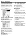
Picture adjustment
Adjustment from personal computer
Although this projector sets proper signal settings set
automatically for the image signal from personal
computers. But, at times, there can be dome
diferences in timings. In this case, press AUTO
POSITION button. If the images are still not projected correctly, use MENU display to adjust the
projected images from personal computers. After
adjustments are made, the new settings can be saved
in user function.
Adjusting the images form personal
computers in MENU display
Adjust as below for the following symptoms.
HOLD ... Select ON, and adjust BEGIN or END for
image which top part is the least curved.
PLL ....... Select FAST, NORMAL, or SLOW for
image which top part is the least curved.
Select AUTO for normal setting.
Image does not move naturally :
Adjust VERT. SYNC. of the menu in SIGNAL - USER
menu. Select AUTO for normal setting.
• Do not change each menu setting in SIGNAL USER menu for normal setting.
Memorizing the setting
1. Select MEMORIZE in SIGNAL menu, and press
the ENTER button.
2. Press the $ or % button to select the memory
which you wish to record (USER 1 or USER 2).
3. Press ENTER button.
Initializing the setting which has been changed
Select RESET in SIGNAL menu, and press ENTER
button.
• When initializing, selection buttons will not work
for about 2 - 18 seconds.
Seeing images in recorded setting.
Select AUTO in SIGNAL menu, and press the$ or
% button to select the memory (USER1 or USER2).
Image moves to right or left :
Adjust HORIZ. POSITION in SIGNAL menu. Press
the % button to move the image to left. Press the $
button to move the image to right.
Image moves to up or down :
Adjust VERT. POSITION in SIGNAL menu. Press
the % button to move the image to upward. Press
the $ button to move the image to down.
Image flickers / Image is out of focus :
Adjust FINE SYNC. in SIGNAL menu.
Wide stripes appear :
Adjust CLAMP POSITION or CLAMP WIDTH of
each menu in SIGNAL - USER menu.
Noise etc. appears on right or left side of image:
Adjust HORIZ. PIXELS of the menu in SIGNAL USER menu.
Noise etc. appears on top or bottom part of image :
Adjust VERT. LINES of the menu in SIGNAL USER menu.
Top part of image curves :
Change the setting of HOLD in SIGNAL menu or
PLL in SIGNAL - USER menu.
20
Resetting the recorded setting
1. Select DELETE in SIGNAL menu, and press
ENTER button.
2. Press the$ or % button to select the memory
which you wish to reset (USER 1 or USER 2).
3. Press ENTER button
The recorded setting will be reset.
The simple way of adjustment
1. Select HORIZ. POSITION in SIGNAL menu.
2. Press the$ or % button to adjust the horizontal
start position (the left end).
3. Select TRACKING in SIGNAL menu.
4. Press the$ or % button to adjust the horizontal
end position (the right end).
5. Repeat steps 1 to 4 for fine adjustment.
6. Select VERT. POSITION in SIGNAL menu.
7. Press the$ or % button to adjust the vertical
start position (the top end).
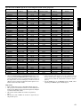
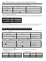
Specification of RGB signals in each computer mode of the projector
TV60
TV50
HiVision
PC98
CGA70
CGA84
CGA85
VGA60
VGA72
VGA75
VGA85
SVGA56
SVGA60
SVGA72
SVGA75
SVGA85
XGA43i
XGA60
XGA70
XGA75
XGA85
SXGA70a
SXGA75a
SXGA85a
SXGA60a
SXGA75a
SXGA43i
SXGA60
SXGA75
MAC13
MAC16
MAC19
MAC21
HP75
HP72
SUN66a
SUN76a
SUN66
SUN76
SGI72
SGI76
IBM60
resolution
(H x V)
–
–
–
640 x 400
640 x 400
640 x 400
640 x 400
640 x 480
640 x 480
640 x 480
640 x 480
800 x 600
800 x 600
800 x 600
800 x 600
800 x 600
1024 x 768
1024 x 768
1024 x 768
1024 x 768
1024 x 768
1152 x 864
1152 x 864
1152 x 864
1280 x 960
1280 x 960
1280 x 1024
1280 x 1024
1280 x 1024
640 x 480
832 x 624
1024 x 768
1152 x 870
1024 x 768
1280 x 1024
1152 x 900
1152 x 900
1280 x 1024
1280 x 1024
1280 x 1024
1280 x 1024
1280 x 1024
horizontal
frequency (kHz)
15.73
15.63
33.75
24.82
31.47
37.86
37.86
31.47
37.86
37.50
43.27
35.16
37.88
48.08
46.88
53.67
35.52
48.36
56.48
60.02
68.68
63.85
67.50
77.49
60.00
75.00
46.43
63.98
79.98
35.00
49.72
60.24
68.59
62.94
78.13
61.85
71.81
71.68
81.13
76.92
82.00
63.42
• When the ZOOM MODE of PRESENTATION menu is set
to 4, by pressing the EXPAND button on the remote control, it will switch to the screen displaying the picture as
its original size (real screen display). In the real screen
display, pictures will be black-framed when picture resolution is lower than 800 ✕ 600.
Vertical
frequency (Hz)
59.94
50.00
60.00
56.42
70.09
84.13
85.08
59.94
72.81
75.00
85.01
56.25
60.32
72.19
75.00
85.06
86.96
60.00
70.07
75.03
85.00
70.01
75.00
85.06
60.00
75.00
86.87
60.02
75.03
66.67
74.55
75.02
74.96
74.92
72.00
66.00
76.63
66.68
76.11
72.30
76.00
60.00
•
•
Normal
(H x V)
800 x 600
800 x 600
800 x 450
800 x 500
800 x 500
800 x 500
800 x 500
800 x 600
800 x 600
800 x 600
800 x 600
800 x 600
800 x 600
800 x 600
800 x 600
800 x 600
800 x 600
800 x 600
800 x 600
800 x 600
800 x 600
800 x 600
800 x 600
800 x 600
800 x 600
800 x 600
768 x 600
768 x 600
768 x 600
800 x 600
800 x 600
800 x 600
800 x 600
800 x 600
768 x 600
768 x 600
768 x 600
768 x 600
768 x 600
768 x 600
768 x 600
768 x 600
Native
(H x V)
–
–
–
640 x 400
640 x 400
640 x 400
640 x 400
640 x 480
640 x 480
640 x 480
640 x 480
800 x 600
800 x 600
800 x 600
800 x 600
800 x 600
1024 x 768
1024 x 768
1024 x 768
1024 x 768
1024 x 768
1024 x 768
1024 x 768
1024 x 768
1024 x 768
1024 x 768
1024 x 768
1024 x 768
1024 x 768
640 x 480
832 x 624
1024 x 768
1024 x 768
1024 x 768
1024 x 768
1024 x 768
1024 x 768
1024 x 768
1024 x 768
1024 x 768
1024 x 768
1024 x 768
ENGLISH
Signal mode
If the resolution and frequency of your computer are not
shown on the table., change the resolution of your computer. You may find the compatible resolution and frequency.
Set the RGB/Y, CB, CR in SIGNAL menu to RGB, when
inputting the HDTV signal as RGB signal.
Important:
• Some computers may not be compatible with the projector.
• The projector's maximum resolution is 800 ✕ 600 pixel.
It may not be displayed correctly for the pictures of higher
resolutions than 800 ✕ 600.
• The picture with a SYNC on G (Green) signal may
jitter.
• The picture with a SYNC on G (Green) signal may be
tinged with green.
21
Advanced feature for presentation
Expand
Still
By pressing the EXPAND button on the remote control, you can view the detailed image of the picture.
How to stop the picture temporarily (still picture)
1. Press the STILL button on the remote control.
The picture will stop temporaly.
Setting the Expand mode
1. Press the MENU button once to display the onscreen menu.
2. Press the $ or % button to select PRESENTATION
menu.
3. Press the ENTER button.
4. Press the{ or } button to select ZOOM MODE or
POSITION.
5. Press the $ or % button to set the ZOOM MODE
or POSITION.
6. Press the MENU button twice to exit the menu system.
ZOOM MODE
(ZOOM MODE1)
(ZOOM MODE2)
Normal
picture
Zooming picture
Normal picture
Zooming picture
(ZOOM MODE3)
(ZOOM MODE4)
Zooming picture
Actual size picture
Using the Expand mode
1. Press the EXPAND button.
A red frame indicating EXPAND area will appear.
• You can magnify different areas of the active picture by pressing the {, }, $ or % button.
• You can change the magnification of the zoomed
area by pressing the + or - button.
2. Press the EXPAND button again.
• Display enlargement does not work with
video input or S-video input.
• In EXPAND mode, do not display the test pattern.
Indication Mode 4 (actual size display)
• Pressing the $, % buttons is for adjusting fine
adjust.
• The expanding rate cannnot be changed either
pressing + or - button.
22
To stop still picture.
2. Press the STILL button on the remote control
again.
• To release the still picture, any buttons also can
be used.
The projector can play back an image by using the PCCARD.
Play back
1. Insert the prerecorded PC-card.
Using the PC-CARD
Use only the flash memory card of PCMCIA•ATA compatible type II.
• Due to PC-CARD type, some images can not be properly recorded. Please contact your dealer.
2. Press the CARD button.
The PC-CARD index display appears on the screen.
Setting up the PC-CARD
1. Set the projector into standby mode by pressing the
main power switch. The POWER indicator lights up
red.
3. Press the $ or % button to select the desired image.
• If the PC-CARD is recorded by using the personal computer, select the desired group by pressing the + or - button.
4. Press the { or } button to enter the image display mode.
2. Press down the PC card slot cover button to open
the PC card slot cover.
5. Press the $ or % button to display another
image.
3. Make sure the PC card is
going to be inserted in
right side. The PC card
indicator will illuminate.
6. Press the VIDEO or RGB button to quit the PCCARD playback function.
When the input source is set to
PC CARD, do not remove the PC card. The projector
may not work correctly.
8. Press the eject button to take the card out.
Removing the PC-CARD
1. Press the RELEASE button on the remote control.
PC card eject icon will be displayed on the right
end of the screen.
The PC card indicator will auto turn off on the
projector.
2. Press down the PC card slot cover button and press
the eject button simultaneously.
3. Remove the PC card from the PC card slot.
• Upon removing a PC card, wait at least 2 seconds
before inserting another.
• The following manufacturer’s PC cards have been
confirmed to operate within this projector:
EPSON, TDK, Logitec, Panasonic, Verbatim, I-O
DATA, HAGIWARA, IBM, Mitsubishi (MF-Series).
7. Press the RELEASE button on the remote
control.
• During PC-CARD playback, the sound is
switched off.
• Noise may occur momentarily when images are
updated via PC card.
• The images recorded in BMP (not compressed)
will take a long time to playback.
• It takes about 10 seconds to playback JPEG
compressed data.
• When having an access of PC card as you want to
exchage images on PC card, there will be four red
line indicated at the edge of the screen.
• If the PC card is ejected when playing back PC
card, the image will be switched to VIDEO
automatically.
• During PC-CARD playback, if the incorrect
display appears, release and re-insert the PCCARD.
Playback picture taken by the digital camera
• The image which has been recorded in PCMCIA/
ATA card, smart media or compact flash can be
playbacked. The PC card adapter is required to
playback smart media and compact flash.
• Depending on the type of the digital camera, the
picture may not appear correctly. Please contact
your dealer.
• PC card recorded by Digital Camera, the picture
will not be displayed on PC-CARD index display.
23
ENGLISH
PC-CARD
PC-CARD (Continue)
To automatically change the image, follow the steps
as shown below.
1. Press the MENU button.
2. Press the $ or % button to select PRESENTATION.
3. Press the ENTER button.
4. Press the { or } button to select AUTO SLIDE
TIME (3 - 99 sec.)
5. Press the $ or % button to set the time for auto
playback.
6. Press the{ or } button to select REPEAT.
7. Press the $ or % button to select ON or OFF.
8. Press the MENU button twice to exit the menu system.
9. Press the PC CARD button.
10. Press the $ or % button to select the desired image.
11. Press the AUTO PLAY button on the remote control.
The image automatically changes according your
setting.
12. Press the AUTO PLAY button on the remote control to quit the PC-CARD automatic playback function.
24
• A gray frame will appear during auto play.
• Button operation will only work when the gray
frame appears on screen. Button operation is not
possible while the red frame is on-screen.
• Auto play can be stopped by pressing the button
except LASER, mouse pointer and R/L-click.
• Auto play cannot be used either during image
enlargement or when menus are displayed.
Advanced feature with PC
PCV (PC Card Viewer)
Installation of software
PC-CARD viewer (PCV) is a utility software that lets
you record and project an image to a PC-CARD by using a personal computer.
For Windows 95 or Windows NT 4.0
1. Start up Windows.
The following system software and hardware are necessary to use the projector.
When you use a Macintosh
• Macintosh series loading 68030 or higher in
CPU and a video card with which more than
256 colors are available
• System7.1 or newer
• More than 8MB of Random-access memory
(RAM) space
When you use Microsoft® Windows®
• Microsoft ® Windows ® 95 Operating System
(Windows 95) or Microsoft ® Windows NT ®
Operating System Version 4.0 (Windows NT
4.0) or Microsoft® Windows® Operating System
Version 3.1 (Windows 3.1) with the CPU
loading 80486SX or higher and a display card
with more than 256 colors are available.
• 16MB or more of RAM available
• We recommend the following hardware.
• 32MB or more of RAM available
• A video display card with full colors are
available
EXPORT LAW ASSURANCES
You acknowledge and agree that the SOFTWARE is subject
to restrictions and controls imposed by the United States
Export Administration Act (the “Act”) and the regulations
thereunder. You agree and certify that neither the
SOFTWARE nor any direct product thereof is being or will
be acquired, shipped, transferred or reexported, directly or
indirectly, into any country prohibited by the Act and the
regulations thereunder or will be used for any purpose
prohibited by the same.
LIMITATIONS OF REMEDIES
Regardless of whether any remedy set forth herein fails of
its essential purpose, in no event will Mitsubishi be liable
to you for any special, consequential, indirect or similar
3. Start up Program Manager.
Click the [Start] button and select the [Run (R)] command. Then the [Run] dialog box is displayed.
4. If you inserted the CD-ROM to drive D, type [D:
Win95\Pcv\Us\Setup95] (Windows 95) or [D:
Winnt40\Pcv\Us\Setupnt] (Windows NT) in the
"command line" text box and click the "OK" button.
The letter [D] may be different according to the
drive you use.
5. When the setup program starts up, follow the onscreen instructions.
6. When the message “Completed” appears on screen,
click the [Finish] button to complete the installation.
• Installation of Microsoft Internet Explorer 3.02 (or
later) is required for optimum unit operation. Use
the Jaaxdist.exe command should the unit appear
to not be performing normally.
For Windows 3.1
1. Start up Windows.
2. Insert the Projector driver CD-ROM into your CDROM drive.
3. Select the [Run (R)] command on the icon menu so
that the dialog box [Run] is displayed.
4. If you inserted the CD-ROM to drive D, type
[D:Win31\Pcv\Us\Setup] in the "command line"
text box and click the "OK" button. The letter [D]
may be different according to the drive you use.
5. When the setup program starts up, follow the onscreen instructions.
6. When the message “completed” appears on screen,
click the [OK] button to complete the installation.
For Macintosh
1. Start up Macintosh.
2. Insert the Projector driver CD-ROM into your CDROM drive.
3. Copy "PCV for Mac” file in the “PCV” folder to
anywhere on the hard disk.
damages, including any lost profits or lost data arising out
of the use or inability to use the SOFTWARE or any data
supplied therewith even if Mitsubishi or anyone else has
been advised of the possibility of such damages, or for any
claim by any other party.
Some states do not allow the limitation or exclusion of
liability for incidental or consequential damages so the
above limitation or exclusion may not apply to you.
In no case shall Mitsubishi’s liability exceed the price for
the SOFTWARE.
25
ENGLISH
Environment
2. Insert the Projector driver CD-ROM into your CDROM drive.
Advanced feature with PC (Continue)
Starting up PCV (For Windows)
For Windows 95 or Windows NT
1. Start up Windows.
2. Insert the PC card to the PC Card slot on the personal computer.
3. Start up Program Manager.
Click the [Start] button and select the [Program
(P)]➔[Pcv]➔[PCV]command.
For Windows 3.1
1. Start up Windows.
2. Insert the PC card to the PC Card slot on the personal computer.
3. Double click the [PCV] icon in the PCV folder.
Command reference (For Windows 95)
The command references are as shown below:
File
New presentation .... Create a new presentation.
Open presentation... Opens an existing presentation.
Close presentation ... Closes an opened presentation.
Save presentation .... Saves an opened presentation
using the same name.
Save presentation As... Saves an opened presentation
to a specified name.
Delete presentation . Delete an opened presentation.
Exit ........................... Exits PCV.
Edit
Cut ............................ Deletes selected image from
the presentation and moves it
to the clipboard.
Copy .......................... Copies selected image data
from the presentation to the
clipboard.
Paste ......................... Pastes image data from the
clipboard into the presentation.
Image
Add image
Image file ............ Inserts image file to an opened
presentation.
Screen capture .... Captures screen and inserts it
to an opened presentation.
Delete image ............ Deletes the selected image
from an opened presentation.
Image information... Displays information of the
selected image.
View
Tool Bar .................... Shows or hides the toolbar.
Drive Bar .................. Shows or hides the drivebar.
Status Bar ................ Shows or hides the status bar.
Window
Cascade .................... Arranges windows in an overlapped fashion.
Tile Horizontal ......... Arranges windows in nonoverlapped horizontal tiles.
Tile Vertical .............. Arrages windows in non-overlapped vertical tiles.
Arrange Icons ........... Arranges icons of closed windows.
Windows 1, 2, ........... Goes to specified window.
Help
26
Help Topics ............... Offers you an index to topics
on which you can get help.
Advanced settings .... Displays a detail setting of
this application.
About PCV ............... Displays the version information of this application.
Command reference (For Windows 3.1)
The command references are as shown below:
File
New presentation .... Create a new presentation.
Open presentation ... Opens an existing presentation.
Close presentation ... Closes an opened presentation.
Save presentation .... Saves an opened presentation
using the same name.
Delete presentation...Delete an opened presentation.
Open image file ........ Import an image from a file.
Exit ........................... Exits PCV.
Edit
Cut ............................ Deletes selected image from
the presentation and moves it
to the clipboard.
Copy .......................... Copies selected image data
from the presentation to the
clipboard.
Paste ......................... Pastes image data from the
clipboard into the presentation.
Tool
Capture .................... Captures screen and inserts it
to an opened presentation.
Delete image ............ Deletes the selected image
from an opened presentation.
View
Tool Bar .................... Shows or hides the toolbar.
Status Bar ................ Shows or hides the status bar.
Index image size ...... Select the size of index image.
Option
Select card drive ...... Select (or change) the PCCARD drive.
Card drive info ......... Display the information of the
selected PC-CARD drive.
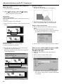
Recording the image (For Windows)
7. Click OK button.
When you wish to record the image of the display to a
PC-CARD.
8. Repeat steps 4 to 7 for other images.
Drive bar
• If you are using Windows 3.1, select ‘Select card
drive‘ in Option menu of PCV main window.
2. Choose [New presentation...] under the [File]
menu.
The new presentation window will open.
3. Choose [Add image] under the [Image] menu and
then choose [Screen capture...].
• The PCV windows disappear and the capture
dialog box appears.
9. Click the return button.
The presentation window will open. The recorded
image appears on the presentation window.
• Depending on the personal computer, the recorded
image can appear incorrectly. In this case, set the
delay time longer by using the Capture setting
dialog box. Then repeat steps 5 to 7 again.
10. Choose [Save presentation...] under the [File]
menu.
• A presentetion which has been recorded
already, Select “Save As...” to save as.
11. Choose [Exit] under the [File] menu to quit from
PCV.
When you wish to record the image from existing files.
Return button
Capture setting buttton
Capture button
• If you are using Windows 3.1, select ‘Image
capture...‘ in TOOL of PCV main window.
4. Display the image you wish to record on the
screen.
5. Click the capture button.
The Compress setting window appears.
1. Choose the PC-CARD drive using the drive bar
under the status bar.
• If you are using Windows 3.1, select ‘Select card
drive‘ in Option menu of PCV main window.
2. Choose [New presentation...] under the [File]
menu.
The new presentation window will open.
3. Choose [Add image] under the [Image] menu and
then choose [Image file...].
• If you are using Windows 3.1, select ‘Open
image file‘ in File menu of PCV main window.
4. Select the image you wish to record.
5. Click OK button.
The recorded image appears on the presentation
window.
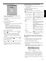
6. Select the compress type.
Compress type
High quality
Standard
Low quality
No compress (BMP)
Speed
Fast
Fast
Fast
Slow
Capacity
Standard
Small
Very small
Large
• You can confirm the compressed image by
clicking the Preview button.
• If the command [Preserving the setting] is
checked , you don’t need to set the style of save
by each image (Not Windows 3.1).
• The maximum number of group (presentation)
that can be recorded to a PC card is 160. If the
capacity of the PC CARD is low, the maximum
number is less than 160.
• The maximum number of the images that can be
recorded to a group is 99.
6. Repeat steps 3 to 5 for other images.
7. Choose [Save presentation...] under the [File]
menu.
8. Choose [Exit] under the [File] menu to quit from
PCV.
27
ENGLISH
1. Choose the PC-CARD drive using the drive bar
under the status bar.
Advanced feature with PC (Continue)
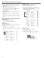
Editing the presentation (For Windows)
Delete the image
1. Select the image to be deleted.
Preview an image
1. Double click the image.
The preview image appears on the displays.
2. Choose [Delete image...] under the [File] menu.
• If you are using Windows 3.1, choose [Delete
image] under the [Option] menu.
Sequencing
A. Exchange images
You can exchange the images among images next to
each other.
1. Select an image to be exchanged.
2. Drag the image and drop on the next or previous
image.
{
2. Click the image by using the left button of the
mouse (or press Enter key on your keyboard.)
Display image information
1. Choose [Image information] under the [Image]
menu.
The image information window appears.
• If you are using Windows 3.1, choose the image
by clicking the right button of the mouse.
B. Move images
You can move images to other positions.
1. Select an image to be moved.
2. Choose OK to close the image information window.
2. Drag the image and drop it on the other image
(except next or previous image).
The image will be moved to the previous position
of the dropped image.
How to save a file which has been made
by a presentation software (For
Windows 95 only)
1. Make up a presentation by the presentation
software.
2. Choose [Print] under the [File] menu.
3. Set to PCV driver for printing name.
{
• PCV drive will automatically be installed in
the system of the personal computer when PCV
is installed.
28
4. Click the properties button.
Starting up PCV (For Macintosh)
1. Start up Macintosh.
2. Insert the PC card to the PC Card slot on the personal computer.
5. If necessary, set the Resolution, Expand, File
Format or JPEG Quality.
6. Click OK button on the PCV driver Properties
dialog box.
7. Click OK button.
8. Choose the PC-CARD drive.
9. Click OK button.
• The presentation data will be saved as PCVdrv
on PC card.
• PCVdrv is a temporaly file. If you record
presentation continuously, the previous data
will be erased. The projector may not work
correctly when playing back “PCVdrv” file on
it. Please follow as below to rename the file.
10. Boot up PCV’s program.
11. Choose [Open presentation...] under the [File]
menu.
12. Select PCVdrv file and click Open button.
The presentation window will open and the
recorded image appears on the presentation
window.
13. Choose [Save presentation As...] under the [File]
menu and click OK button.
14. Click Yes(Y) button.
15. Choose [Exit] under the [File] menu to quit from
PCV.
• The file recorded with PCV driver cannot show
the index display until re-recorded by PCV software.
Command reference
The command references are as shown below:
File
Create New presentation . Create a new presentation.
Open presentation... Opens an existing presentation.
Close presentation ... Closes an opened presentation.
Save presentation .... Saves an opened presentation
using the same name.
Delete presentation . Delete an opened presentation.
Open image file... ..... Import an image from a file.
Done ......................... Exits PCV.
Edit
Cut ............................ Deletes selected image from
the presentation and moves it
to the clipboard.
Copy .......................... Copies selected image data
from the presentation to the
clipboard.
Paste ......................... Pastes image data from the
clipboard into the presentation.
Clear... ...................... Deletes the selected image
from an opened presentation.
Option
Preference... ............. Select the format BMP or
JPEG.
Get Screen Shot Image .... Captures screen and inserts it
to a presentation.
Recording the image (For Macintosh)
When you wish to record the image of the display to a
PC-CARD.
1. Display the image you wish to record on the screen.
2. Press the shift button, command button and
number 3 button simultaneously.
3. Repeat steps 1 and 2 for other images.
4. Choose [Get Screen Shot Image] under the [Option] menu.
The presentation window will open. The recorded
image appears on the presentation window.
• The file type to be recorded is BMP or JPEG. To
change file type, select [Preference] under the
[Option] menu then change setting. Reboot PCV.
5. Choose [Save presentation...] under the [File] menu.
6. Choose [Done] under the [File] menu to quit from
PCV.
29
ENGLISH
3. Double click the [PCV for Mac] icon.
Advanced feature with PC (Continue)
When you wish to record the image from existing files.
1. Choose [Create New presentation...] under the
[File] menu.
The new presentation window will open.
2. Choose [Open image file] under the [File] menu.
3. Select the image you wish to record.
B. Move images
You can move images to other positions.
1. Select an image to be moved.
2. Drag the image and drop it on the other image
(except next or previous image).
The image will be moved to the previous position
of the dropped image.
4. Click OK button.
The recorded image appears on the presentation
window.
5. Choose [Save presentation...] under the [File]
menu.
{
6. Choose [Done] under the [File] menu to quit from
PCV.
Editing the presentation (For Macintosh)
Delete the image
1. Select the image to be deleted.
2. Choose [Clear] under the [File] menu.
Sequencing
A. Exchange images
You can exchange the images among images next to
each other.
1. Select an image to be exchanged.
2. Drag the image and drop on the next or previous
image.
Preview an image
1. Select an image to be previewed.
2. Double click the image.
The preview image appears on the displays.
{
30
Mouse remote control
By connecting to personal computer throughth PS/2 (or ADB) port, you can operate your computer with the
projector remote control.
Connection
ENGLISH
Projector + IBM PC or IBM PC compatibles
to RS-232C
terminal
to mouse
(PS/2) port
PS/2 adapter
Mini DIN 6P
RS-232C cable
D-SUB 9P
D-SUB 9P
Mini DIN 8P
Projector + Macintosh
to ADB port
to RS-232C
terminal
MAC adapter
for MOUSE
Mini DIN 4P
RS-232C cable
D-SUB 9P
D-SUB 9P
Mini DIN 8P
Operation
POWER
RGB
VIDEO
PC CARD
AUTO
POSITION
RELEASE
AUTOPLAY
left click
LASER
MENU
This operates in the same
way as the left button on
the computer mouse.
mouse pointer
Use to move the cursor on the image,
instead of the computer mouse.
R-CLICK
right click
This operates in the same way as the right
button on the computer mouse.
ENTER
• If the mouse remote control is not working, restart the computer.
31
Replacement of a light source lamp
The light source lamp is designed to project the image
on the LCD panels. When the light source lamp no
longer functions, replace it with a new one to ensure
optimum performance.
Caution:
• Do not remove the light source lamp from inside of
this equipment immediately after using the projector, you may get burned because of the high temperature of the light source lamp.
• When you replace the light source lamp, press the
power button to power off, then wait for 120 seconds in stand-by mode to cool down the lamp and
LCD panels. Turn off the main switch, unplug the
power cord from the outlet and wait one hour so that
the lamp is cooled to the touch.
• Do not remove the light source lamp except for replacement. Careless treatment can cause injury or
fire.
• Do not touch the lamp element directly. It may be
broken and may cause you to injure or burn yourself.
• Be sure not to drop the screws into the projector.
Also be sure not to insert metal or any flammable
objects, it may cause fire or an electric shock. If any
objects are inserted, please unplug and contact your
dealer.
• Install the lamp securely, failure may cause fire.
4. Hold onto the projector by the handle as you pull
out the lamp.
Once the lamp has been removed, do not spill liquid
on it, place it near flammable objects or where children can touch it. Otherwise, it will cause injury or
fire.
5. Insert the new lamp securely into the projector body
in the right direction.
6. Tighten up the screws (a) which have been removed
in step 3 using a phillips screwdriver (+).
(a)
1. Stand the projector as
shownin the direction of the
arrow.
Screw of the lamp lid
2. Loosen the screws of the
lamp lid on the top cover using a phillips screwdriver
(+) , and remove the lid.
• Remove the lamp cover in
the direction of the arrow
as indicated.
7. Tighten up the screws of the lamp lid using a
phillips screwdriver (+).
3. Loosen screws (a) using a phillips screwdriver (+),
and remove them.
(a)
• Do not lose the screws.
32
How to reset the operation time meter
Plug in the power cord, switch on the projector and reset lamp time by pressing the $, % and POWER buttons simultaneously.
ENGLISH
Caution:
• The lamp you have removed, do not spill liquids on
it, place it near flammable objects or where children
can touch it. Otherwise, it will cause injury or fire.
• Be sure that the projector guide is firmly inserted
between the right and left lamp guides.
Important:
• The projector will not turn on if you do not secure
the lamp lid.
• The operation time meter must be reset after the
lamp has been replaced.
• Do not reset the operation time meter unless the
lamp has been replaced.
The life of the lamp
The average life of the lamp for the projector is about
2,000 hours of consecutive use. Life span may differ
according to operating environment, and may be shorter
than 2,000 hours. Decreases in luminescence and/or
color brightness will indicate that the light source lamp
is in need of replacement. When lamp operation time
exceeds 1,500 hours, the indicator will flash alternately
between green and red (while the lamp is in operation;
when the lamp is not in operation, the indicator will
appear red only). When the lamp has been used for
about 1,900 hours, the message “LAMP!!.” will appear
on the screen for one minute. When the lamp has been
used for about 2,000 hours, the projector will automatically shut off for the safety of the lamp and the power
indicator light up in red. The projector cannot be used
until the lamp has been replaced and operation timer
has been reset.
Caution:
• The light source lamp is fragile. If broken be careful
not to cut yourself with glass fragments.
• The lamp life depends on the environment. For replacement lamps, please contact your dealer.
The projector automatically shuts off when
the lamp is used up in about 2,000 hours
and the projector wont come on until the
lamp is exchanged and operation timer
reset.
33
Maintenance
Caution:
Be sure to turn off the projector and unplug the power
cord from the wall outlet before you perform any maintenance on the projector.
Cleaning the air-filter
Clean the air-filter frequently. If the filter or ventilation slots become clogged with dirt or dust, the temperature inside of the projector may rise and shut off
the power (the TEMP indicator starts to blink red).
1. Press and raise the air-filter cover with a screwdriver
(–).
Caution:
Be sure to use the projector with an air-filter. If not,
dust may get inside the projector, causing a fire or a
breakdown.
Cleaning the projector and the ventilation
slots
Use a soft cloth to clean the projector and the ventilation slots. When the slots become dirty, wipe them with
a soft cloth dampened with a diluted mild detergent,
and then wipe them with a dry cloth.
To protect the surface of the projector from fading or
deteriorating:
• Do not spray insecticide on or inside the
projector.
• Do not use benzine or thinner to clean it.
• Do not let rubber or plastic materials come into
contact with the projector.
Cleaning the lens
Use a standard lens-cleaning brush or a piece of lens
tissue dampened with lens cleaning fluid. The lens surface is fragile. Use only recommended, nonabrasive lenscleaning materials. Do not touch the lens with your fingers.
2. Wash the air-filter.
Use water or a mild detergent diluted with water to
clean the filter. Rinse the filter thoroughly and let it
dry completely. If the filter is damaged or becomes
extremely dirty, contact your dealer for replacement
information.
3. Attach the air filter to the cover.
FILTER
FILTER COVER
4. Reinstall the air-filter cover.
Note: The power will not turn on if the air-filter cover
is improperly installed.
34
Troubleshooting
The following offers solutions to some of the common problems you may encounter. We suggest that you consult
this chart before contacting your dealer.
CAUSE
The power is off.
• The air intake vents, exhaust vents or air filter
is clogged with dust or some object.
POWER indicator does not light up.
• Power cord is unplugged from the outlet.
• Power cord is disconnected from the projector.
• The main switch is turned off.
• The lamp lid is open.
POWER indicator blinks red.
• The projector has been turned on again too soon
after having been turned off.
• When the power switch was turned off while
the fan was running, during or after lamp
operation.
• The room temperature is too high.
(Does the LAMP indicator show an unusual
condition?)
• Lamp is no longer working.
POWER indicator blinks between red and green.
• The filter cover or lamp cover is not closed.
• When the LAMP indicator or the TEMP
indicator is either on or blinking, the main unit
requires repairs.
POSSIBLE SOLUTIONS
• Remove the object.
•
•
•
•
Plug the power cord into the outlet.
Insert the power cord into the projector.
Turn the main switch on.
Close the lamp lid.
• Wait for the lighting sequence.
• Turn the power switch on and off several times.
• Refer to "Indicators" on page 36.
• Replace the lamp with a new one.
• Close the cover correctly.
• Contact your dealer.
• Lens is covered by lens cap.
• When the LAMP indicator or the TEMP
indicator is either on or blinking, the main unit
requires repairs.
No picture appears
The equipment connected to this projector is not
•
on the screen.
turned on.
• Hookup is not made correctly with other equipment.
• The input source is not selected correctly.
• Take the lens cap off.
• Replace the lamp with a new one.
The image is
distorted.
• Adjust the angle of the projector to make a right
angle to the screen. See page 11.
• The projector is not at a right angle to the screen.
• Turn on the connected equipment.
• Confirm the hookup.
• Select the correct source according to the equipment connected to this projector.
The image is dark. • Brightness, tint and color are not adjusted cor- • Adjust brightness, tint and color correctly.
rectly.
• The projecting distance is beyond the focused area.
• Lens is dirty.
• Screen size exceeds screen size specifications.
•
•
•
•
Adjust the projecting distance. See page 10.
Clean lens.
Reduce screen size to within 23" to 245".
The image is
blurred.
• Brightness and contrast are not adjusted correctly.
• FINE adjustment is not made correctly.
• Tracking is not adjusted.
• The projector is not at a right angle to the screen.
The image remains
blurred.
• When you see the stationary image for a long time, it may remain on the screen if you change the
image. It is not a breakdown. The blurred image will disappear in a few minutes.
Adjust brightness, contrast.
• Make FINE adjustment.
• Adjust tracking.
• Adjust the angle of the projector to make a
right angle to the screen. See page 11.
Red, blue or green dots • It is normal.
are viewed on the text of
image.
The image is
distorted on the
screen and noise is
heard.
• The cable for connection with other equipment
is not plugged securely into the terminal.
• The projector is installed too close to other
equipment.
• Plug the connecting cable securely into the
terminal. See pages 12-14.
• Install the projector far away from other
equipment.
No sound is heard.
• Volume is not turned up.
• Connection to other equipment is not made
correctly.
• Turn up the volume.
• Check connections.
See pages 12-14.
• The PC monitor is not turned on.
• Turn on the monitor.
Nothing is displayed on
the PC monitor.
Warm air comes out of
the exhaust vents.
Adjustments cannot be
made.
• This is typical of the LCD projector.
• The operation is incorrectly made due to noise or
interference.
• Press the MENU and POWER buttons simultaneously. See page 17.
35
ENGLISH
PROBLEMS
Indicators
The projector has three indicators each of which shows the working condition of the projector.
The following offers solutions to possible problems. If a problem persists, turn the projector off and consult your
dealer.
SOURCE
LAMP
RGB
TEMP
VIDEO
CARD
PC CARD
MENU
ENTER
VOL
INDICATOR
TEMP
INDICATOR
SHOWS
blinking red
CONDITION
• Unusual temperature
The power is turned off
and the POWER indicator
lights up red.
• The ventilation slots or air
filter is clogged with dust
or debris.
• The fan has stopped due
to an impediment.
• The room temperature is
too high.
• The filter is dirty.
Steady green
LAMP
INDICATOR
Normal
Blinking red/green Lamp is almost used up.
or Blinking red
Steady red
• Lamp is used up.
• The power is not turned on.
POSSIBLE SOLUTIONS
• Remove the object from
the ventilation slots.
• Pull out the power
plug and remove the
object. If you cannot,
consult your dealer.
• Relocate the projector
to a cooler place.
• Clean the filter.
-
Replace the lamp.
Exchange with a new
lamp if the same
problem recurs.
(Power indicator lights up red.)
Steady red
Standby
-
Steady green
Power-on
-
• The filter cover is not closed.
POWER
(When the TEMP indicator and
INDICATOR Blinking red/green
the LAMP indicator are off.)
or Blinking red
• Abnormal
(When the TEMP indicator
or the LAMP indicatorsteady on or blinking.)
36
• Close the cover correctly.
• Contact your dealer.
Type
LCD projector
Model
LVP-S120A
Rated power supply
AC100 ~ 240V, 50 / 60Hz
Rated input
2.3A
LCD panels
0.9-inch LCD panel: 3 pieces (for R, G, B)
ENGLISH
Specifications
Pixels
800 × 600 = 480,000 pixels
Total 1,440,000 pixels
Active pixel rate: 99.99 % or more (each panel)
Projection lens
F 1.8~2.1
Light source lamp
150 W DC marcury lamp
Picture size
23~245 inch (aspect ratio 4:3)
Audio output
1 W monaural
Speaker
6 cm square type (8Ω 1W) ×
S-video input
Luminance signal: 1.0 Vp-p 75Ω (negative sync.)
Chroma signal: 0.286 Vp-p 75Ω (burst signal)
Video input
1.0 Vp-p 75Ω (negative sync.)
Audio inputs
350 mVrms, 10kΩ or more
Analog RGB input
(mini D-SUB 15P)
f = 36 ~ 47 mm
1 pcs.
RGB: 0.7Vp-p 75Ω (negative sync.)
YCBCR: Y:1.0Vp-p (negative sync.) CBCR:0.7Vp-p
HD/CS : TTL level (positive or negative)
VD : TTL level (positive or negative)
PC audio input
350 mVrms, 10kΩ or more
Control connector
Serial (Mini DIN 8 pin female connector) RS-232C standards
Outside dimensions
264 ×115 ×340 mm
(width × height ×
Weight
Approx. 10 lbs (4.5kg)
Length of power cord
114 inch (2.9m)
ø3.5mm stereo mini jack
Legs are not included.
depth)
Temperature, humidity
(performance guarantee) +41°F (+5°C) ~ +95°F (+35°C), 30~90%
Replacement parts list
What’s included in the box
1 AC power cable
246C346-10
1 RCA video cable
246C323-10
1 Remote control
1 Warranty card
939P763-10
854B318-10
1 Audio cable
242C938-10
1
User’s manual
871D275-10
1
RGB cable for PC
246C318-10
1
Software (CD-ROM)
919P116-10
1
MAC adapter for RGB cable
246C319-20
2
Battery for remote
–
1
1
RS-232C cable
246C366-10
MAC adapter for RS-232C cable 246C321-10
1
PS/2 adapter
246C367-10
1
MAC adapter for MOUSE
246C368-10
Accessories
1 Spare marcury-arc lamp
1 PC audio cable
499C004-01
242D493-10
37
S120
MODEL
LVP-S120A
APPENDIX
LCD
Projector
User Manual
Control this projector by using a personal computer
This projector can be controlled by connecting a personal computer with RS-232C terminal.
Connection
Projector + IBM PC or IBM PC compatibles
to RS-232C
terminal
to Com1
Comport
RS-232C cable
D-SUB 9P
Note:
Mini DIN 8P
If your PC (IBM or IBM compatible) is equipped only with a 25-pin serial port connector,
a 25-pin serial port adapter is required. Contact your dealer for details.
Projector + Macintosh
to modem port
or printer port
RS-232C adaptor
for Macintosh
Mini DIN 8P
D-SUB 9P
to RS-232C
terminal
RS-232C cable
D-SUB 9P
Mini DIN 8P
Functions can be controlled by a personal computer:
• Turn the ON or OFF
• Changing input signals
• Button input by remote control
• Reading warning data
• Picture adjustment
By making a programme, you can also control this projector by a personal computer automatically.
[EXAMPLE]
Time
Movement
8:40 a.m.
Turn the power ON
Change input to RGB
Turn the power OFF
Turn the power ON
Change input to VIDEO
Turn the power OFF
0:20 p.m.
1:00 p.m.
3:00 p.m.
5:20 p.m.
Commands to be used (ASCII code)
00!
00_r1
00"
00!
00_v1
00"
1) Interface
PROTOCOL
RS-232C
BAUD RATE
9600 [bps]
DATA LENGTH
8 [bits]
PARITY BIT
STOP BIT
NONE
1 [bits]
FLOW CONTROL
NONE
This projector uses RXD, TXD and GND lines for RS-232C control.
For RS-232C cable,the reverse type cable should be used.
2) Control command diagram
The command is structured by the address code, function code, data code and end code. The length of the
command is different by each function.
ASCII
Address code
30h 30h
Function code
Function
Data code
Data
'0' '0'
Function
Data
[Address code]
[Function code]
[Data code]
[End code]
End code
0Dh
30h 30h (In ASCII code, '0' '0') fixed.
A code of each fixed control move
A code of each fixed control data (number) and not always indicated.
0Dh (In ASCII code, ' ') fixed.
3) Control sequence
(1)
(2)
(3)
(4)
•
The command from a personal computer to the projector will be sent in 400ms.
The projector will send a return command 400ms* after it has received an encode. if the command isn’t
received correctly, the projector will not send the retirn command.
The personal computer checks the command and confirms that if the command which has been sent has
been executed or not.
This projector sends various codes, other than the return code. When having a control sequence by RS232C, reject other codes from personal computer side.
* : The sending time of return command may delay depending on the condition (during changing the input
signal, playing back the PC card, etc.).
APPENDIX
HEX
Control this projector by using a personal computer (Continue)
[Example] Turn the power ON (' 'is for ASCII code)
Sending commands
Status code from
from the PC etc.
30 30 21 0D
'0' '0' '!' '
Meaning
projector
Command for POWER ON
'
30 30 21 0D
Command received
'0' '0' '!' '
(Command echo back)
'
4) Operation commands
The operation commands execute the basic operation setting of this projector.It may not operate when changing
the signal.
POWER ON
POWER OFF
INPUT RGB
INPUT VIDEO
INPUT CARD
ASCII
!
"
_r1
_v1
_c1
HEX
21h
22h
5Fh 72h
5Fh 76h
5Fh 63h
31h
31h
31h
• POWER OFF command will not work for 1 minute after the power is turned on.
• POWER ON command will not work for 1 minute after the power is turned off.
[Example] Set the input signal to RGB (' 'is for ASCII code)
Sending commands
from the PC etc.
Status code from
projector
30 30 5F 72 31 OD
'0' '0' '_' 'r' '1' ' '
Meaning
Command for setting the input
signal to RGB
30 30 5F 72 31 OD
'0' '0' '_' 'r' '1' ' '
Command received
(Command echo back)
5) Remote commands
The some remote control operation can be done by remote command codes.
Button's name on remote
+ VOLUME
– VOLUME
EXPAND
{
}
$
%
MENU
ENTER
AUTO PLAY(PC CARD)
RELEASE(PC CARD)
AUTO POSITION
STILL
ASCII
r06
r07
r02
r53
r2b
r4f
r59
r54
r10
r32
r22
r09
ra4
HEX
72h
72h
72h
72h
72h
72h
72h
72h
72h
72h
72h
72h
72h
30h
30h
30h
35h
32h
34h
35h
35h
31h
33h
32h
30h
61h
36h
37h
32h
33h
62h
66h
39h
34h
30h
32h
32h
39h
34h
[Example] Display MENU selection bar. (' 'is for ASCII code)
Sending commands
from the PC etc.
Status code from
projector
30 30 72 35 34 OD
'0' '0' 'r' '5' '4' ' '
Meaning
Command as same as MENU button
30 30 72 35 34 OD
'0' '0' 'r' '5' '4' ' '
Command received
(Command echo back)
6) Warning commands
Read the past warning data. The personal computer doesn’t attache the data code onto the warning commands to
send. On the other hand, the projector which has received a command, attach the warning data as the data code
to reply.
ASCII
Ep
Ec
past data
clear past data
HEX
45h 70h
45h 63h
The past data
Ep* (* is 6 digits, hexadecimal notation)
*=(MBS)b1,b2,b3,b4,b5,b6,b7,b8, b9, b10, b11, b12, b13, b14, b15, b16, b17, b18, b19, b20, b21, 000(LSB)
b1=Operation time (during boot up '0' / when the power is ON, '1')
b2=Standby power short
b3=Switch power short
b4=0
b5=0
b6=0
b7=The fan is stopped.
b8=The lamp cover is not closed.
b9=The filter cover is not closed.
b10=The temperature sensor is off (Exausting fan)
b11=The temperature sensor is off (The lamp)
b12=Communication error between microcomputer
b13=Communication error between microcomputer (Parallel bus)
b14=Abnormal temperature (the lamp)
b15=Abnormal temperature (outside)
b16=Abnormal temperature (LCD)
b17=The lamp is not illuminating.
b18=Confirmation mode for the operating status
b19=0
b20=0
b21= The life of a lamp
The fan was down when the power was ON and the past data of the warning was confirmed.
Sending commands
Status code from
from the PC etc.
30 30 45 70 OD
'0' '0' 'E' 'p' '
Meaning
projector
Commnd for confirm past data
'
30 30 45 70 38 32 30 30 30 30 0D
APPENDIX
[Example 1]
Warning command (Fan is stopped when
'
'0' '0' 'E' 'p' '8' '2' '0' '0' '0' '0' '
the power is ON) carried out
*: '8' '2' '0' '0' '0' '0' mean the numbers as shown below
Bit
b1 b2 b3 b4
b5 b6 b7 b8
b9 b10 b11 b12
ASCII
1
0
0
HEX
0
0
0
8
0
1
0
2
0
0
0
b13 b14 b15 b16
0
0
0
0
0
0
b17 b18 b19 b20
0
0
0
0
b21 0
0
0
b1=1 (The power is ON), b7=1 (The fan is stopped), Other=0
7) Reading command diagram
Monitor projector operation status. The power ON, OFF and input terminal settings can be monitored.
POWER ON
POWER OFF
INPUT RGB
INPUT VIDEO
INPUT CARD
Function
vP
vP
vI
vI
vI
ASCII
Data (Receive)
1
0
r1
v1
c1
Function
76h 50h
76h 50h
76h 49h
76h 49h
76h 49h
HEX
Data (Receive)
31h
30h
72h 31h
76h 31h
63h31h
0
0
0
0
0
0
Control this projector by using a personal computer (Continue)
When a personal computer sends the command, data code will not be attached. On the othe hand, the projector
which has received a command will attach the recent operating status then send.
[Example ] Input was Video 1 when the operating status of the input terminal was confirmed.
Sending commands
from the PC etc.
30 30 76 49 OD
'0' '0' 'v' 'I' ' '
Status code from
projector
Meaning
Commnd for confirm input
30 30 76 49 76 31 0D
'0' '0' 'v' 'I' 'v' '1' ' '
Command (Input is Video)
carrired out
8) Picture adjustment commands
The picture adjustment commands execute the picture adjustment setting of this projector. If the personal computer doesn’t
send the commands without attaching the data code, the projector which has received the command replays the setting data
as data code.
CONTRAST
BRIGHTNESS
SHARPNESS
TINT
COLOR
ASCII
HEX
P
Q
R
S
T
50h
51h
52h
53h
54h
How to set the grade
The data code of CONTRAST and BRIGHTNESS is structured by the difference data of R from G, the main data and the difference
data of B from G. Use ASCII letters code to set the grade for setting data. Please refer to the table below for HEX code.
ASCII
HEX
'+'
2Bh
[Example 1]
'–'
2Dh
'0'
30h
'1'
31h
'2'
32h
'3'
33h
'4'
34h
'5'
35h
'6'
36h
'7'
37h
'8'
38h
Set the difference data of R from G to +10, the setting main data to 0 and the difference data of
B from to -5.
Sending commands
from the PC etc.
30 30 50 2B 31 30 2B 30 30 2D 30 35 0D
'0' '0' 'P' '+' '1' '0' '+' '0' '0' '-' '0' '5' ' '
Status code from
projector
30 30 50 2B 31 30 2B 30 30 2D 30 35 0D
'0' '0' 'P' '+' '1' '0' '+' '0' '0' '-' '0' '5' ' '
[Example 2]
'9'
39h
Meaning
Command for setting the
picture control
Command received
(Command echo back)
The TINT was set to +10 when the setting status was confirmed.
Sending commands
from the PC etc.
30 30 53 0D
'0' '0' 'S' ' '
Status code from
projector
Meaning
Command for confirm
setting of TINT
Command (setting of TINT
is +10) carried out
30 30 53 2B 31 30 0D
'0' '0' 'S' '+' '1' '0' ' '
• When the command of CONTRAST or BRIGHTNESS is sent from the computer, the setting of the COLOR
TEMP on the menu is set to “USER”.
• For the same condition as “HIGH” or “LOW” of the COLOR TEMP, change the CONTRAST and
BRIGHTNESS settings as shown below.
COLOR TEMP “HIGH”
COLOR TEMP “LOW”
difference data
of R from G
difference data
of B form G
CONTRAST
-10
+10
BRIGHTNESS
+00
+00
difference data
of R from G
difference data
of B form G
CONTRAST
+10
-10
BRIGHTNESS
+00
+00
MITSUBISHI ELECTRONICS AMERICA, INC.
5665 Plaza Drive
Cypress, CA 90630
871D275A1
Printed in Japan