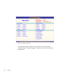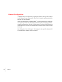
1
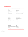
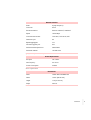
User’s Manual:
UCCI
Universal Communication Controller Improved
Serial Synchronous/Asynchronous to Network Communication Interface
Software Revision 2.03
•
•
• I
•
•
•
Copyright ©2007, ADD-Engineering B.V.
Online version copyright © 2007
All rights reserved.
Printed in the Netherlands
This document is protected by Copyright Protection Laws. The online
version of this document may be freely printed and distributed internally,
but cannot be modified, in whole or in part, or included in any other work
without prior written consent from ADD-Engineering B.V.
Limitation of Liability
ADD-Engineering B.V. makes NO WARRANTY, EXPRESSED or
IMPLIED, with respect to this user-manual, and any related items, its
quality, performance, merchantability, or fitness for any particular use. It is
solely the purchaser’s responsibility to determine its suitability for any
particular use. Information contained in this document is subject to change
without notice.
Trademark credits
The following are trademarks of ADD-Engineering B.V.
Universal Communication Controller Improved
Universal Communication Controller
HIT Interface Controller
Netmate
SyncMate-MKII
SyncMate
ClockMate
II
•
•
•
•
•
•
Contents
••••••
Chapter 1
Introduction
5
Functional Description
6
Field Of Application
7
Specification Overview
8
Chapter 2
Front and back panel
Front panel
11
Back panel
12
11
Chapter 3
Web User Interface
Chapter 4
Channel Setup
15
Channel Configuration
16
Serial Data Format
17
Bit Encoding
19
Bit Order
21
Sync Pattern
22
Strip Sync
23
Frame-Length
24
Bit Stuffing/Insertion
25
Idle-State
26
Checksum-Mode
27
Synchronous Speed
28
Clock-source
29
13
•
•
• 1
•
•
•
Clock Line Inversion
30
Data bits
30
Stop bits
31
Parity bit
31
Async Speed
32
Network Encapsulation Format
Buffering Time Out
34
Size Header
34
Network Transport
35
Local Port
35
Destination Address
35
Destination port
36
Channel State
36
Multiplexer
37
Network Transport
37
Buffering Time Out
38
Local Port
38
Destination Address
38
Destination Portnumber
39
Channel State
39
Overview
40
Chapter 5
2
•
•
• Contents
•
•
•
Channel Logging
41
Channel Logging
42
RX Data
43
TX Data
43
System Log
44
Export Logging
45
Debug Messages
46
Information Messages
46
Configuration Messages
46
Rx Data Messages
46
Tx Data Messages
46
Warning Messages
46
Error Messages
46
Logging Export Server
47
33
Chapter 6
Chapter 7
Statistics Overview
49
Channel Statistics
50
Bytes Received
50
Frames Received
51
Idles Received
51
Checksum/CRC-Errors
51
Bytes Transmitted
51
Frames Transmitted
51
Idles Transmitted
51
Transmit Underruns
51
Bytes Received [network]
51
Packets Received [network]
52
Packets Ignored [network]
52
Bytes Transmitted [network]
52
Packets Transmitted [network]
52
Transmit Packets Overflow [network]
Receive Packets Overflow [network]
All Channels
53
Network
54
Transport
54
Localport
54
Remote Address
54
State
55
RxBytes/s
55
TxBytes/s
55
System Management
57
User Management
58
Old Username
58
New Username
58
Old Password
58
New Password
59
Retype New Password
IP-Configuration
60
MAC Address
60
IP-Address
60
Netmask
60
52
52
59
Contents
•
•
• 3
•
•
•
Gateway
61
Time Configuration
62
Time Source
62
IP-Address
63
Time Zone
63
Default Configuration
64
Reboot System
65
Firmware Upgrade
66
Transmit Buffers
67
Text version
68
Chapter 8
Connecting the UCCI
Power
69
DTE Ports
69
Network Ports
70
Appendix A
Warranty and Maintenance
Appendix B
Cables and Connectors
Appendix C
ANFI Network Format
Index
4
69
•
•
• Contents
•
•
•
83
71
75
79
Chapter 1
Introduction
••••••
Congratulations on purchasing your UCCI from ADD-Engineering. The
Universal Communication Controller Improved combines dedicated
communication hardware with on-board data processing software to
provide an efficient means of interfacing networked enabled applications
located at your host system to (remote) synchronous and asynchronous Data
Communication Equipment. By doing this the UCCI off-loads
communications overhead from your host system’s CPU for optimum
system performance and creates a virtual hardware layer between your host
system and the Data Communication Equipment.
•
•
• 5
•
•
•
Functional Description
The Universal Communication Controller Improved (UCCI) is a device that
establishes the interface from standard Ethernet TCP/IP communication
channels (TCP-client, TCP-server and UDP) to standard as well as "nonstandard" synchronous/asynchronous systems (non-standard in terms of
Commercially Of The Shelf equipment).
The UCCI can interface 8 synchronous/asynchronous systems to 8 network
channels simultaneously. The UCCI supports a variety of datalink protocols
like Link-1, Link-11B, SIMPLE, ATDL, HDLC, LAPB, Synchronous
transparent, Asynchronous transparent and the flexible Universal-mode
(which is well known from the Universal Communication Controller, UCC).
To provide flexibility and create a wide adaptation level within these
different modes, the UCCI has wide a number of parameters which can be
altered to interface to specific protocols. Synchronisation word, bit
encoding and bit stripping are only a couple of these parameters. Though the
UCCI is designed from a total new concept, a lot of its functionality on the
serial communication side is comparable to that of the UCC.
The UCCI goes way beyond the functionality of the UCC in terms of
flexibility, ease of installation, ease of configuration, time synchronisation
possibilities, logging- and data field extraction capabilities. The UCCI
provides remote monitoring and configuration of the unit by means of a
standard html-based web-interface and the use of any "brand" of webbrowser available. System configuration security is guaranteed by a
configurable username and password combination.
6
•
•
•
•
•
•
Chapter 1
Field Of Application
The versatility of the UCCI allows the unit to be employed in a large number
of applications. The following is just a summary of a large range of possible
applications for the UCCI:
•
•
•
•
•
•
•
•
•
•
•
Interface between networked applications and UKADGE/NADGE/MASE using
Link-1
Interface between networked SIMPLE Gateways and SIMPLE synchronous
communication links
Interface between networked Ship Shore Ship Buffer applications and Link-11B
synchronous communication links
Interface between networked ASTERIX processing software and HDLC
synchronous communication links
Interface between networked tactical data link distribution and visualization
software (like NIRAS) and a large number of synchronous as well as asynchronous
communication links
Interface between networked tactical data link filter software and synchronous as
well as asynchronous communication links
Interface between networked track-to-track/plot-to-track correlators and
synchronous as well as asynchronous communication links
Analysis/test tool (using the logging capability) to detect possible problems on
synchronous as well as asynchronous communication links
Interface between networked tactical data link translation software and a large
number of synchronous as well as asynchronous communication links
Remote serial ports, by using two UCCI’s "back-to-back" connected to a WAN a
maximum of 8 synchronous/asynchronous serial ports can be distributed across a
single TCP/IP connection (using the Multiplexer functionality)
Receive only interface between tactical data collection software and
UKADGE/NADGE/MASE using the Link-1 Keep Alive functionality.
Introduction
•
•
• 7
•
•
•
Specification Overview
DTE Synchronous/Asynchronous Interface
Ports
8
Connector
DB25 DTE (male)
Electrical Interface
RS-232
Synchronous Speed
300, 600, 1200, 2400, 4800, 9600, 19k2,
38k4, 64k, 128k bps
Asynchronous Speed
75, 110, 300, 600, 1200, 2400, 4800,
9600, 19k2, 38k4, 115k2 bps
Stopbits (async only)
1, 2
Parity modes (async only)
None, mark, space, odd, even
Databits (async only)
5, 6, 7, 8
Clock mode
Internal, Dpll, External
Clock source
input: TxC, RxC, output: ExC
Flow Control
RTS/CTS
Sync Length (Universal Mode)
5...16 bits
Frame Length (Universal Mode)
1..254 bytes
BIt Encoding
NRZ, !NRZ, NRZI, !NRZI
Sync Stripping/Insertion (Universal Mode) On/Off
Bit Stripping/ Insertion (Universal Mode)
On/Off
SizeHeader
On/Off
Clock inversion
On/Off
Checksum Generation (Universal Mode)
Off/Xor/Xnor
Idle State
1, 0, Alternating
Available signals
CTS, RTS, TxD, RxD, DCD, DTR, TxC,
RxC, ExC
Specification of DTE interface
8
•
•
•
•
•
•
Chapter 1
Network Interface
Ports
2 (only use port 1)
Connector
RJ-45
Electrical Interface
Ethernet 10Base-T, 100Base-T
Speed
10/100 Mbps
Communication modes
TCP-client, TCP-server, UDP
Webserver port
80
Export logging port
717
Firmware upgrade port
818
Default username/password
admin/admin
Default IP-address
192.168.0.100
Specification of network interface
Power Requirements
AC Input
115 - 230 V
Net Frequency
50 - 60 Hz
Power Consumption
25 Watt
Power requirements
Dimensions
Case
19 inch rack mountable unit
Width
19 inch (482.60 mm)
Height
1 HU (44.45 mm)
Depth
220 mm
Dimensions
Introduction
•
•
• 9
•
•
•
•
•
10 ••
•
•
Chapter 1
Chapter 2
Front and back panel
••••••
Front panel
The front panel of the UCCI is designed to provide the user a clear view on
the per channel link status. A channel’s status is indicated by means of three
differently colored LEDs.
The red LED (top) indicates that a frame is received on the serial line, the
yellow LED (center) indicates that a frame is transmitted on the serial line
and the green LED (bottom) indicates the connection state of the TCP/IP
connection.
Furthermore the multiplexer LEDs (the group under MUX) provide
information on the status of the network multiplexer. The LEDs indicate the
same as the channel specific LEDS exept that the LEDs now indicate
transmission and reception from the network.
The power LED indicates if power is applied to the unit. During the start-up
phase the channel LEDs will light up from left to right (and back) and the
power LED will be blinking.
ADD-Engineering
PWR
CH1
RX
TX
CN
CH2
CH3
CH4
CH5
CH6
CH7
CH8
MUX
UCCI
UNIVERSAL COMMUNICATION CONTROLLER IMPROVED
Front-panel of the UCCI
•
•
• 11
•
•
•
Back panel
Back-panel of the UCCI
The back-panel of the UCCI holds the power switch, the fused IEC power
inlet, two RJ-45 sockets for the Ethernet network connectivity and eight
DB25-male connectors for serial synchronous and asynchronous
connectivity. Users should use the RJ-45 socket with the designation
"network-1". When replacing the fuse for the UCCI never use a different
fuse than recommended on the back of the unit (1.5A slow blow).
•
•
12 ••
•
•
Chapter 2
Chapter 3
Web User Interface
••••••
The UCCI is equipped with a HTTP-server that provides a very intuitive
web user interface. The user interface can be accessed with any modern
standard web browser currently available (Firefox, Internet Explorer,
Netscape etc).
Before being able to use the web user interface the user should log on to the
UCCI by providing a username/password combination.
Web user interface logon screen
The default username/password combination is admin/admin. It is
recommended to change username/password combination after installation.
The latter could protect your configuration settings from being changed by
unauthorized personnel.
After the provided set of credentials has been verified and validated the
main menu of the web user interface will be shown.
•
•
• 13
•
•
•
Web user interface main menu
The following chapters will discuss the function of the menu groups
“Channel Setup”, “Channel Logging”, “Statistics Overview” and “System
Management”
•
•
14 ••
•
•
Chapter 3
Chapter 4
Channel Setup
••••••
The Channel Setup menu group allows the user to configure the Universal
Communication Controller Improved for a wide range of military and nonmilitary protocols and electrical interfaces. The Channel Setup menu group
also shows a Multiplexer and an Overview. Each of these items will be
discussed separetely in this chapter.
Web interface Channel Setup menu group
•
•
• 15
•
•
•
Channel Configuration
A channel can be configured by selecting the link for that specific channel
in the Channel Setup menu group. There are 8 channel configuration links,
thus one for each channel.
Please note that when a “Submit-button” is placed right from a menu item,
it is required to click the “Submit-button” first before continuing with the
channel configuration. After the “Submit-button” has been clicked the menu
items that are not relevant to submitted the selection will be removed from
the menu.
By clicking the “Save all-button”, all settings for the specific channel will
be stored and the channel will be restarted.
•
•
16 ••
•
•
Chapter 4
Web interface Channel Configuration menu
Serial Data Format
Serial data format selects the type of “serial protocol” for that specific
channel. After selecting a specific channel type, the parameters that are
of no use for the serial data format are hidden after clicking at the
“Submit button” (at the right from the drop-down selection box).
Channel Setup
•
•
• 17
•
•
•
The UCCI currently provides 10 serial data formats, Link-1, Link-11B,
ATDL, Universal, Transparent, HDLC, Link-1 K.A., SIMPLE, Async and
LAPB.
•
•
•
•
•
•
•
•
•
•
Link-1
The serial data format that enables reception and transmission of Link-1
(STANAG-5501) frames. Link-1 data exchange through the network consists of 1
start-group, 14 data groups and 1 check group to add up to a frame of 16 bytes.
Link-11B
The serial data format that enables reception and transmission of Link-11B
(STANAG-5511) frames. Link-11B data exchange through the network consists of
6 data-groups and 1 check-group to add up to a frame of 7 bytes.
ATDL
The serial data format that enables reception and transmission of ATDL (ATDL
D1) frames.ATDL data exchange through the network consists of 7 data-groups
and 1 check-group to add up to a frame of 8 bytes.
Universal
The flexible serial data format well known from the UCC that provides a wide
range of configurable parameters to adapt the channel to a specific protocol.
Transparent
The serial data format well known from the UCC that provides a fully transparent
interface to and from a synchronous serial communication line.
HDLC
The serial data format that enables the reception and transmission of HDLC frames
(including CRC-verification and generation).
Link-1 K.A.
Like Link-1 but Link-1 K.A.sends S0.S0 test-frames at 10 second intervals as an
indication to an (N)ADGE that the remote side (the UCCI) is still alive. The UCCI
will also reply to S.14 acknowledge receipt messages as specified in STANAG5501, APPENDIX 4 to ANNEX C. Link-1 K.A. data exchange through the
network consists of 1 start-group, 14 data groups and 1 check group to add up to a
frame of 16 bytes.
SIMPLE
The serial data format that enables the reception and transmission of SIMPLE
frames (STANAG-5602). SIMPLE data exchange through the network consists of
the complete SIMPLE frame received/transmitted on the serial communication
line.
Async
The serial data format that provides a transparent interface to systems using
asynchronous communication.
LAPB
Link Access Procedure Balanced, the serial data format that is built on top
of HDLC to provide the capability to establish a link between two systems.
Data between these systems will be exchanged in the form of INFO-frames.
•
•
18 ••
•
•
Chapter 4
Bit Encoding
Receiver
Bit-encoding for the receiver can be described as the way the line-state is
decoded to a received bit. With the UCC it is possible to specify 4 different
bit-encoding methods, NRZ, !NRZ, NRZI, !NRZI
•
NRZ
Generally known as Non Return to Zero, the line-state is directly decoded
to form a bit. A logical ‘1’ on the physical line is "decoded" to a bit with the
value ‘1’. A logical ‘0’ on the physical line is "decoded" to a bit with the
value ‘0’.
•
!NRZ
Almost the same as NRZ but in this case all bits are simply inverted. A
logical ‘1’ on the physical line is "decoded" to a bit with the value ‘0’ in
memory. A logical ‘0’ on the physical line is "decoded" to a bit with the
value ‘1’.
•
NRZI
Generally known as Non Return to Zero Inverted. Although the name
implies that it is just the inverted version of NRZ, there is a more significant
difference between these two. To decode the line-state to a bit in NRZI
requires knowledge of the previous line-state. If there is a difference
between the previous line-state and the actual line-state then it is decoded to
a bit with the value ‘0’. If there is no difference between the previous and
the actual line-state then it is decoded to a bit with the value ‘1’. In short,
transitions will be decoded to form a bit with the value ‘0’ and steady states
will be decoded to form a bit with the value ‘1’.
•
!NRZI
Almost the same as NRZI but in this case all bits are simply inverted.
Transitions will be decoded to form a bit with the value ‘1’ and steady states
will be decoded to form a bit with the value ‘0’.
Transmitter
Bit-encoding for the transmitter can be described as the way the bits which
need to be transmitted are encoded to a line state.
•
NRZ
Channel Setup
•
•
• 19
•
•
•
Generally known as Non Return to Zero, the bit is directly encoded to form
a line-state. A bit with the value ‘1’ is encoded to the physical line-state 1.
A bit with the value ‘0’ is encoded to the physical line-state ‘0’.
•
!NRZ
Almost the same as NRZ but in this case all bits are simply inverted first. A
bit with the value ‘1’ is encoded to the physical line-state ‘0’. A bit with the
value ‘0’ is encoded to the physical line-state ‘1’.
•
NRZI
To encode the bit to transmit to a line-state in NRZI requires knowledge of
the previous line-state. If a bit with the value ‘0’ needs to be encoded then
the line-state should alter, so the actual line-state should be the inverted
version of the previous line-state. If a bit with the value ‘1’ needs to be
encoded the actual line-state should be the same as the previous line-state.
In short, bits with the value ‘0’ will be encoded as transitions and bits with
the value ‘1’ will be encoded as steady-states.
•
!NRZI
Almost the same as NRZI but in this case all bits are simply inverted first.
In short, bits with the value ‘1’ will be encoded as transitions and bits with
the value ‘0’ will be encoded as steady-states.
•
•
20 ••
•
•
Chapter 4
Bit Order
Receiver
For the receiver the bit-order can best be described as the order in which the
synchronously/asynchronously received bits are submitted to the network.
The most commonly used bit-order is LSB-first, however some applications
require the opposite.
•
LSB-FIRST
The bit which is received first at the synchronous/asynchronous line will be
placed at the LSB-position of the byte which will be submitted to the
network. No bit-reversal is taking place.
•
MSB-FIRST
The bit which is received first at the synchronous/asynchronous line will be
placed at the MSB-position of the byte which will be submitted to the
network. In short it means that bit 0 becomes bit 7, bit 1 becomes bit 6 and
so on.
Transmitter
For the transmitter the bit-order can best be described as the order in which
the received bytes from the network are transmitted by the
synchronous/asynchronous transmitter. The most commonly used bit-order
is LSB-first, however some applications require the opposite.
•
LSB-FIRST
The bit at the LSB-position of the byte received from the network will be
transmitted first by the synchronous/asynchronous transmitter. No bitreversal is taking place.
•
MSB-FIRST
The bit at the MSB-position of the byte received from the network will be
transmitted first by the synchronous/asynchronous transmitter. In short it
means that bit 0 becomes bit 7, bit 1 becomes bit 6 and so on.
Channel Setup
•
•
• 21
•
•
•
Sync Pattern
The Sync-Pattern can have a length in the range [5..16] bits. The SyncPattern is displayed in the web user interface with the MS-bit left and the
LS-bit at the right. The Sync-Pattern is transmitted/received with the LS-bit
first. Note that the way the Sync-Pattern is represented in the web user
interface is different from the UCC and SyncMate.
Receiver
The Sync-Pattern specifies the sync-word on which the receiver will
synchronise. The sync-pattern is compared after bit-decoding takes place.
When the Sync-Pattern has been detected in the incoming data stream the
device is considered to be in-sync.
Transmitter
The Sync-Pattern denotes the start of a frame. The pattern will be
transmitted if there are bytes in the internal buffer. If there are less bytes in
the buffer than the specified frame-length, the UCCI will transmit the bytes
in the buffer and fill up the remaining bytes (which were possibly not
submitted) with idle bits. The Sync-Pattern is fully user definable.
•
•
22 ••
•
•
Chapter 4
Strip Sync
To provide the user with the possibility to strip or not to strip the sync-word
from the synchronously received data or to insert or not to insert the syncword into the synchronously transmitted data, this option is implemented in
the UCCI.
Receiver
•
NOSTRIP
The synchronously received sync-word is submitted to the user application
through the network connection. In case the bit-order is reversed the syncword will also be reversed.
•
STRIP
The number of synchronisation bits are stripped from the synchronously
received data. In other words the sync-word is stripped from the data.
Transmitter
•
NOSTRIP
NOSTRIP in this context actually means no-insertion. No insertion of a
sync-word takes place at the synchronous transmitter side. The user
application has to submit the sync-word through the network connection.
•
STRIP
STRIP here means that the sync-word is inserted by the UCCI in case a new
frame needs to be transmitted. The sync-word which is inserted is specified
by the pattern "Sync-Pattern".
Channel Setup
•
•
• 23
•
•
•
Frame-Length
The frame-length is selectable in the range of [1..254]. In general the FrameLength is the number of bytes the user application will submit through the
network connection or can expect from the network connection. The latter
with some exceptions which can be read hereunder.
Receiver
With the Fame-Length parameter the number of bytes that the user
aplication expects is specified. The number of bytes are submitted through
the network connection. All the bytes which are received are included in the
Frame-Length. So, in case the sync-word is not stripped the Sync-Word will
count as part of the total Frame-Length.
Transmitter
With the Frame-Length parameter the number of bytes which the user
application will submit through the network connection is specified. In case
the Sync-Word is not stripped, the Sync-Word should be submitted by the
user application through the network connection and thus will count as part
of the Frame-Length. However, if a checksum-mode is selected, one byte
less should be submitted while the UCCI is generating its own checksum to
be forwarded with the data.
•
•
24 ••
•
•
Chapter 4
Bit Stuffing/Insertion
Specific bits are stripped from the data at the receiver's side and inserted at
the transmitter's side.
Receiver
At the receiver's side (synchronous) the specified bit will be stripped from
the data. The insert parameter in this menu is of no significance for the
receiver's side. The bitposition parameter specifies which bit will be
stripped after reception of the Sync-Word. Assuming the Sync-Word is
found and the strip/insert parameter is set to bitposition ‘1’, insert ‘0’. Then
the first bit after the Sync-Word is stripped from the data (in case SyncStripping is also enabled), then the next 8 bits are forwarded to the network
connection and the next "first" bit is stripped from the data. This continues
until all the bytes of the frame are received.
Transmitter
At the transmitter's side (synchronous) the specified bit will be inserted in
the data. The insert parameter in this menu specifies if a ‘0’ or a ‘1’ will be
inserted. Assuming the Sync-Word has already been transmitted (and syncstripping is also enabled) and the strip/insert parameter is set to bitposition
‘1’, insert ‘0’. Then the first bit transmitted after the sync-word will be a ‘0’.
After that a byte that is submitted through the network connection will be
forwarded to the synchronous port and then another ‘0’ will be inserted.
This continues until all the bytes of the frame are transmitted.
Channel Setup
•
•
• 25
•
•
•
Idle-State
The Idle-State is used to specify the behaviour of the transmitter in the case
that there are no bytes to transmit. The Idle-State is directly related to the
line-state and thus no bit-encoding will take place. There are three possible
idle-states, ‘0’, ‘1’ and ALT.
Receiver
This parameter is of no significance for the receiver.
Transmitter
•
‘0’
Idle in zero's, invalid for NRZI and !NRZI bit encoding methods.
•
‘1’
Idle in one's, invalid for NRZI and !NRZI bit encoding methods.
•
ALT
Idle in alternating states, normally this is used to keep receivers with DPLL
in sync.
•
•
26 ••
•
•
Chapter 4
Checksum-Mode
Checksums can be generated by the UCCI, it means that the user does not
have to calculate checksums over the data submitted to the UCCI. The
checksum is transmitted as the last byte of a frame. The Checksum-Mode
has three options, OFF, XOR and XNOR.
Receiver
The checksum-mode parameter is of no significance in the receiver.
Transmitter
The checksum calculated using the method defined above is attached to the
frame as a last byte.
•
OFF
No checksum is attached to the frame
•
XOR
An XOR (exclusive or) will be performed over all the bytes in the frame
(except the sync-word).
•
XNOR
An XNOR (inverted exclusive or) will be performed over all the bytes in the
frame (except the sync-word).
Channel Setup
•
•
• 27
•
•
•
Synchronous Speed
The Synchronous Speed parameter of the UCCI has only significance if INT
(internal clock) or DPLL (digital phase locked loop clock) is enabled. In
other cases the transmit/receive clock submitted will dictate the
synchronous speed. Thus, when using external clock, the user is not limited
by the selection of synchronous speeds down here.
•
•
•
•
•
•
•
•
•
•
300
Data is clocked in and out at 300 bps.
600
Data is clocked in and out at 600 bps.
1200
Data is clocked in and out at 1200bps.
2400
Data is clocked in and out at 2400bps.
4800
Data is clocked in and out at 4800 bps.
9600
Data is clocked in and out at 9600 bps.
19k2
Data is clocked in and out at 19200 bps.
38k4
Data is clocked in and out at 38400 bps.
64k
Data is clocked in and out at 64000 bps.
128k
Data is clocked in and out at 128000 bps.
Receiver
Data is clocked in at the selected speed.
Transmitter
Data is clocked out at the selected speed.
•
•
28 ••
•
•
Chapter 4
Clock-source
With the UCCI it is possible to select three different clock-domains. The
first most commonly used is the external (EXT) clock-mode, the second is
the internal (INT) clock-mode and the third and last is the digital pll (DPLL)
clock-mode.
•
•
•
INT
The internal clock-mode is used when the UCCI should generate the clocking
signals required. The synchronous clock-speed can be selected from the
Synchronous-Speed menu. The clock which is generated internally is placed on pin
24 (ETCLK) of the DB25-male connector.
DPLL
The digital pll clock-mode is used when synchronous data is coming in at a known
synchronous bit-rate but not accompanied by a clock signal. The synchronous
clock-speed can be selected from the Synchronous-Speed menu. The clock which
is generated internally is placed on pin 24 (ETCLK) of the DB25-male connector.
The internally generated clock is synchronised continuously with the received data,
or better with the transitions in this data.
EXT
With the external clock-mode clock-signals should be connected to the UCCI at pin
17 (RCLK) and pin 15 (TCLK) of the DB25-male connector. The RCLK is
timebase related to the data on pin 3 (RxD) and the TCLK is timebase related to the
data on pin 2 (TxD). The TCLK and RCLK need not to be related, however usually
they are.
Receiver
Data is clocked in at the rate specified by the clock-signal.
Transmitter
Data is clocked out at the rate specified by the clock-signal.
Channel Setup
•
•
• 29
•
•
•
Clock Line Inversion
The UCCI has the capability to invert the clock signals used for synchronous
data communication. Inverting the clock signals could be a requirement
when connecting to MIL-STD data communication equipment.
•
•
OFF
No inversion of the clock signals takes place. The unit operates with a clock
polarity that is used with industry standard communication equipment. This means
that data is clocked out at the rising edge of TxClk and data is clocked in at falling
edge of RxClk (all at RS-232 level). Please note that the inversion operates
different from the UCC where no clock inversion requires a ‘!’.
ON
Inversion of the clock signals takes place. The unit operates with a clock polarity
that is used with military standard communication equipment. This means that data
is clocked out at the falling edge of TxClk and data is clocked in at rising edge of
RxClk (all at RS-232 level).See remark about UCC in ‘OFF’.
Receiver
Data is clocked in at the appropiate edge.
Transmitter
Data is clocked out at the appropiate edge.
Data bits
Data bits only applies to protocols using an asynchronous communication
port. Data bits defines the number of bits that comprise a character
exchanged on the asynchronous communication line.
•
•
•
•
•
•
30 ••
•
•
Chapter 4
DATA 8
A character exchanged on the asynchronous communication line comprises 8 data
bits.
DATA 7
A character exchanged on the asynchronous communication line comprises 7 data
bits.
DATA 6
A character exchanged on the asynchronous communication line comprises 6 data
bits.
DATA 5
A character exchanged on the asynchronous communication line comprises 5 data
bits.
Stop bits
Stop bits only applies to protocols using an asynchronous communication
port. Stop bits defines the number of bits that follow a character exchanged
on the asynchronous communication line.
•
•
STOP 1
One stop bit will follow after each character exchanged.
STOP 2
Two stop bits will follow after each character exchanged.
Parity bit
Parity bit only applies to protocols using an asynchronous communication
port. Parity bit defines the type of parity bit that follows an exchanged
character on the asynchronous communication line.
•
•
•
•
•
NONE
No parity bit.
MARK
Parity bit is “mark”.
SPACE
Parity bit is “space”.
ODD
Parity bit is “odd”.
EVEN
Parity bit is “even”.
Channel Setup
•
•
• 31
•
•
•
Async Speed
Async Speed only applies to protocols using an asynchronous
communication port. Async Speed defines the at which speed the bitelements of a character being clock in or out.
•
•
•
•
•
•
•
•
•
•
•
•
•
32 ••
•
•
Chapter 4
75
Data is clocked in and out at 75 bps
110
Data is clocked in and out at 110bps
300
Data is clocked in and out at 300 bps
600
Data is clocked in and out at 600 bps
1200
Data is clocked in and out at 1200 bps
2400
Data is clocked in and out at 2400 bps
4800
Data is clocked in and out at 4800 bps
9600
Data is clocked in and out at 9600 bps
19k2
Data is clocked in and out at 19200 bps
38k4
Data is clocked in and out at 38400 bps
115k2
Data is clocked in and out at 115200 bps
Network Encapsulation Format
The UCCI has the capability to pack multiple frames received from the
serial communication line into one packet and transmit the assembled
packet on the network. Also, the UCCI has the capability to unpack a packet
received from the network and forward the separate frames to the serial
communication line. There is an infinite number of possibilities to
encapsulate data, however the UCCI currently supports three network
encapsulation formats, Transparent, ANFI and ANFI-MUX.
•
•
•
TRANSPARENT
Frames received from the serial communication line are forwarded transparently to
the network communication channel. Except the possibility of a Size Header that
can be prepended to the data, no encapsulation takes place. Frames received from
the network channel will be forwarded transparently (except a possible Size
Header) to the serial communication line.
ANFI
Frames received from the serial communication line are packed together to form a
packet. The packet will be forwarded to the network communication channel.
Packets received from the network communication channel will be disassembled
and the separate frames will be forwarded to the serial communication line. See the
appendices for further specification on the ANFI network encapsulation format.
ANFI-MUX
Frames received from the serial communication line are forwarded to the
Multiplexer-channel of the UCCI to be combined with other channels using the
Multiplexer capability. The packet will be forwarded to the network in the way that
has been specified by the Multiplexer parameters. Packets received from the
network communication channel of the Multiplexer will be disassembled into
serial frames. In case the serial data format of a specific serial frame matches the
addressed serial communication channel the serial data frame will be forwarded to
the specified channel.
Channel Setup
•
•
• 33
•
•
•
Buffering Time Out
Buffering time out can be used to specify the time the packed data (serial
data frames packed in an ANFI-packet) is held in the buffer before being
sent out to the network. In other words, everytime a serial data frame is
received the timer is reset, when the timer reaches its threshold the data
packed so far will be sent out to the network. A value of “0” means that there
is no time out. The data will be sent out to the network when the complete
ANFI-packet length reaches a size threshold of 1400 bytes.
Size Header
Size header is an option that is only used in the Transparent network
encapsulation format to place the size of the frame in front of the frame
itself.
•
•
•
•
34 ••
•
•
Chapter 4
OFF
No size header is placed (or expected ) in front of the data transmitted/received
through the network communication channel.
ON
A size header is placed (or should be placed in case of the user application) in front
of the data being sent through the network communication channel. The size header
is a two byte value (actually 16 bits unsigned) with the LS-Byte being sent first.
The maximum size of a frame sent through the transparent network encapsulation
format with Size Header “ON” thus is 65535.
Network Transport
The UCCI supports three different ways of exchanging data through the
TCP/IP based Ethernet network. UDP, TCP/CLT and TCP/SRV.
•
•
•
UDP
User Datagram Protocol, this means of transport is not connection oriented, there
is no guarantee that a datagram sent out on the network will reach is destination.
Nor is there any means of flow control. However, in case multiple systems would
require to listen to the same data it could be efficient to broadcast the data through
UDP.
TCP/CLT
Transmission Control Protocol-Client, this means of transport is connection
oriented which means that a connection should be established between local and
remote system before exchange of data can take place. The client part in this
terminology means that the UCCI will actively set up the connection to the remote
side (server).
TCP/SRV
Transmission Control Protocol-Server, this means of transport is connection
oriented which means that a connection should be established between local and
remote system before exchange of data can take place. The server part in this
terminology means that the UCCI will passively wait for any incoming connections
from a remote system (client).
Local Port
The local port has only significance for UDP and TCP-server network
transport mechanisms. It defines which port receives the data when using
UDP as a network transport mechanism and it defines the port that accepts
incoming connections from remote clients when using TCP-server as a
network transport mechanism. Recommended range [1024..65535].
Destination Address
The destination address has only significance for UDP and TCP-client
network transport mechanisms. It defines the address to which the datagram
will be sent when using UDP as a network transport mechanism and it
defines the remote server address to which the UCCI should connect to
when using the TCP-client network transport mechanism.
Channel Setup
•
•
• 35
•
•
•
Destination port
The destination port has only significance for UDP and TCP-client network
transport mechanisms. It defines the “end-port” of the destination address to
which datagrams will be sent when using UDP as a network transport
mechanism and it defines the port at which the remote server is listening
(and normally thus accepting connections) and the UCCI should connect to
when using the TCP-client network transport mechanism.
Channel State
Channel state provides the option to enable or disable the specific
communication channel on the UCCI.
•
•
•
•
36 ••
•
•
Chapter 4
ENABLED
The channel is enabled, operational.
DISABLED
The channel is disabled.
Multiplexer
The UCCI has a multiplexing/demultiplexing capability that enables the
exchange data from multiple serial channels through one single TCP/IP
channel. An application for this capability could be to connect two UCCI’s
back-to-back (with respect to the network side) and in this way extend the
distance between two systems to infinite for a maximum of 8 serial
channels.
Web interface Multiplexer Configuration menu
Network Transport
The Multiplexer supports three different ways of exchanging data through
the TCP/IP based Ethernet network. UDP, TCP/CLT and TCP/SRV.
•
•
UDP
User Datagram Protocol, this means of transport is not connection oriented, there
is no guarantee that a datagram sent out on the network will reach is destination.
Nor is there any means of flow control. However, in case multiple systems would
require to listen to the same data it could be efficient to broadcast the data through
UDP.
TCP/CLT
Transmission Control Protocol-Client, this means of transport is connection
oriented which means that a connection should be established between local and
Channel Setup
•
•
• 37
•
•
•
•
remote system before exchange of data can take place. The client part in this
terminology means that the UCCI will actively set up the connection to the remote
side (server).
TCP/SRV
Transmission Control Protocol-Server, this means of transport is connection
oriented which means that a connection should be established between local and
remote system before exchange of data can take place. The server part in this
terminology means that the UCCI will passively wait for any incoming connections
from a remote system (client).
Buffering Time Out
Buffering time out can be used to specify the time the packed data (serial
data frames packed in an ANFI-packet) is held in the buffer before being
sent out to the network. In other words, everytime a serial data frame is
received the timer is reset, when the timer reaches its threshold the data
packed so far will be sent out to the network. A value of “0” means that there
is no time out. The data will be sent out to the network when the complete
ANFI-packet length reaches a size threshold of 1400 bytes.
Local Port
The local port has only significance for UDP and TCP-server network
transport mechanisms. It defines which port receives the data when using
UDP as a network transport mechanism and it defines the port that accepts
incoming connections from remote clients when using TCP-server as a
network transport mechanism. Recommended range [1024..65535].
Destination Address
The destination address has only significance for UDP and TCP-client
network transport mechanisms. It defines the address to which the datagram
will be sent when using UDP as a network transport mechanism and it
defines the remote server address to which the UCCI should connect to
when using the TCP-client network transport mechanism.
•
•
38 ••
•
•
Chapter 4
Destination Portnumber
The destination port number has only significance for UDP and TCP-client
network transport mechanisms. It defines the “end-port” of the destination
address to which datagrams will be sent when using UDP as a network
transport mechanism and it defines the port at which the remote server is
listening (and normally thus accepting connections) and the UCCI should
connect to when using the TCP-client network transport mechanism.
Channel State
Channel state provides the option to enable or disable the multiplexer on the
UCCI.
•
•
ENABLED
The multiplexer is enabled, operational.
DISABLED
The multiplexer is disabled.
Channel Setup
•
•
• 39
•
•
•
Overview
The Configuration Overview shows a summary of the channel
configurations for all of the UCCI’s channels. The heading above each
column from the table is self explanatory (see Channel Configuration for
details). Disabled channels are identified by a greyed-out row in the table.
Web interface Configuration Overview menu
•
•
40 ••
•
•
Chapter 4
Chapter 5
Channel Logging
••••••
The Channel Logging menu group allows the user to configure the logging
options available in the UCCI. The UCCI has serial a data logging facility
for each of the serial communication channels, a global system logging and
the capability of exporting the log messages to an external system.
The logging capabilities in the UCCI are included as a means for fault
finding when connecting the UCCI to external systems. For reason of
performance it is not recommended to use the serial data capability
continuously. For this reason the serial data logging is disabled each time a
channel is (re)started. The latter thus means that the serial data logging
configuration is not stored permanently in any configuration setting.
All of the logging takes place in RAM, therefore all of the logging is
volatile. Powering off the unit will delete all the log messages from the
memory. The UCCI has a capacity to hold 10000 log records in memory in
a sort of circular buffer fashion. When the last log record (10000) has been
written the next written log record will overwrite the first log record (1). The
maximum number of log records displayed on a log page is limited to 1000
(to avoid long downloading times when requesting a log page).
•
•
• 41
•
•
•
Web interface Channel Logging menu group
Channel Logging
Channel logging provides the capability to log data received and/or
transmitted on the serial line. For protocols like Link-1 and Link-11B a
textual interpretation of the data is displayed as well as the data itself. For
protocols like HDLC, SIMPLE and LAPB only a textual interpretation will
be displayed. For serial data formats like Transparent, Universal and Async
only the data will be displayed.
By clicking the "Logging On-button", the logging is for the specific
channels is enabled (and the "Logging On-button" changes into "Logging
Off". Clicking the "Logging Off-button" disables the logging.
Clicking the "Refresh-button" will cause the browser to refresh the content
of the page and will cause the page to reflect the most recent log contents.
Clicking the "Clear-button" will delete all the RXDATA/TXDATA log
entries for the specific channel from the log buffer.
•
•
42 ••
•
•
Chapter 5
On the bottom right side of the screen there are a number of buttons labeled
"1","2","3","4","5","6","7","8","S". These are shortcuts to jump from one
channel logging to another. The "S" is to jump to the system logging.
Web interface Channel Logging menu
RX Data
The RXDATA displays the data received on the serial communication line
and/or a textual interpretation of the data.
TX Data
The TXDATA displays the data transmitted on the serial communication
line and/or the textual interpretation of the data.
Channel Logging
•
•
• 43
•
•
•
System Log
System logging provides a view on the events taking place in the UCCI.
There are several levels of severity, in order of increasing severity these are
"DEBUG","INFO","CONFIG","WARNING" and "ERROR". Before the
message of each log record the number (1..8) or character (M, S) identifies
the origin of the log record. Where the numbers identify the channels, the
"M" identifies the Multiplexer and the "S" identifies the System.
Clicking the "Refresh-button" will cause the browser to refresh the content
of the page and will cause the page to reflect the most recent log contents.
Clicking the "Clear-button" will delete all the log entries displayed from the
log buffer.
On the bottom right side of the screen there are a number of buttons labeled
"1","2","3","4","5","6","7","8","S". These are shortcuts to jump from one
channel logging to another. The "1" is to jump to the logging of channel 1.
Web interface System logging menu
•
•
44 ••
•
•
Chapter 5
Export Logging
Export Logging facilitates storage of log messages on an external system.
By connecting to the export log service port (port number 717), log
messages (serial received/transmitted data) in textual format can be received
from the UCCI. The log messages are formatted in pretty much the same
fashion as represented in the web user interface. The UCCI provides users
the ability to select specific severity levels through the configurable log
filter. For instance, by selecting Rx Data Messages and Tx Data Messages
only the serial data received and transmitted on the serial ports is exported
through the export log service port. As an example one could use "telnet" to
connect to the export log service port (eg. telnet 192.168.0.100 717). Please
note that when the export log is not able to write to the client (for instance
because of flow control at TCP/IP level as a result of buffers that fill up), the
connection is closed automatically.
Clicking on the "Save all-button" configures and restarts the export log
server.
Web interface Export logging menu
Channel Logging
•
•
• 45
•
•
•
Debug Messages
Checking this box (at the right side) enables export of log messages with the
"DEBUG" severity level
Information Messages
Checking this box (at the right side) enables export of log messages with the
"INFORMATION" severity level
Configuration Messages
Checking this box (at the right side) enables export of log messages with the
"CONFIGURATION" severity level
Rx Data Messages
Checking this box (at the right side) enables export of log messages with the
"RXDATA" severity level
Tx Data Messages
Checking this box (at the right side) enables export of log messages with the
"TXDATA" severity level
Warning Messages
Checking this box (at the right side) enables export of log messages with the
"WARNING" severity level
Error Messages
Checking this box (at the right side) enables export of log messages with the
"ERROR" severity level
•
•
46 ••
•
•
Chapter 5
Logging Export Server
•
•
ENABLED
The logging export server is enabled. Clients can connect to the TCP/IP service
port.
DISABLED
The logging export server is disabled. Clients already connected to the TCP/IP
service port will be disconnected.
Channel Logging
•
•
• 47
•
•
•
•
•
48 ••
•
•
Chapter 5
Chapter 6
Statistics Overview
••••••
The Statistics Overview menu group provides the user a number of views on
the UCCI’s statistics. The UCCI provides per channel statistics, a global
overview on the serial and network statistics for all channels and a global
overview on the channel’s network bandwidth usage and network
connection state (when applicable).
Web interface Statistics Overview menu group
•
•
• 49
•
•
•
Channel Statistics
The Channel Statistics provide a detailed overview of the statistics per
channel. The Channel Statistics page is automatically refreshed to represent
the most recent statistics. The Channel Statistics are divided into two area’s,
serial statistics and network statistics.
Clicking the "Refresh-button" will cause the content of the page to be
refreshed.
Clicking the "Reset-button" will cause set all the statistics displayed on the
page to 0.
Web interface Channel Statistics menu
Bytes Received
Displays the number of bytes received through the serial communication
line.
•
•
50 ••
•
•
Chapter 6
Frames Received
Displays the number of frames received through the serial communication
line.
Idles Received
Displays the number of idles (in bytes) received from the serial
communication line.
Checksum/CRC-Errors
Displays the number of checksum errors or CRC-errors (HDLC/LAPB).
Bytes Transmitted
Displays the number of bytes transmitted on the serial communication line.
Frames Transmitted
Displays the number of frames transmitted on the serial communication
line.
Idles Transmitted
Remains 0.
Transmit Underruns
Remains 0.
Bytes Received [network]
Displays the number of bytes received from the network for the specific
channel.
Statistics Overview
•
•
• 51
•
•
•
Packets Received [network]
Displays the number of packets received from the network for the specific
channel.
Packets Ignored [network]
Displays the number of packets that did not pass the network encapsulation
validation criteria.
Bytes Transmitted [network]
Displays the number of bytes transmitted to the network for the specific
channel.
Packets Transmitted [network]
Displays the number of packets transmitted to the network for the specific
channel.
Transmit Packets Overflow [network]
Displays the number of packets that are discarded because transmission to
the destination was not possible (for instance because of congestion).
Receive Packets Overflow [network]
Remains 0.
•
•
52 ••
•
•
Chapter 6
All Channels
The Statistics Overview provides a detailed overview of the statistics of all
channels. The Channel Statistics page is automatically refreshed to
represent the most recent statistics. The Statistics Overview is divided into
two area’s, serial statistics and network statistics.
Clicking the "Refresh-button" will cause the content of the page to be
refreshed.
Clicking the "Reset-button" will cause set all the statistics displayed on the
page to 0.
Web interface Statistics overview menu
Statistics Overview
•
•
• 53
•
•
•
Network
The Network Statistics provides a detailed overview of the network
statistics/performance of all channels. The Network Statistics page is
automatically refreshed to represent the most recent statistics.
Web interface Network statistics menu
Transport
Displays the network transport mechanism that has been selected for the
specific channel. The possible transport mechanisms are TCP/SRV,
TCP/CLT and UDP.
Localport
Displays the local port number used to exchange data across the network.
Remote Address
Displays the address of the remote side (if applicable) in the format IPaddress:portnumber
•
•
54 ••
•
•
Chapter 6
State
Displays the state of the network connection for the specific channel.
Possible states are "Trying connect", "Connected", "Disconnected" and "-".
RxBytes/s
Represents the number of bytes received per second calculated over a 2
second interval.
TxBytes/s
Represents the number of bytes transmitted per second calculated over a 2
second interval.
Statistics Overview
•
•
• 55
•
•
•
•
•
56 ••
•
•
Chapter 6
Chapter 7
System Management
••••••
The System Management menu group provides access to a number of
UCCI-wide management facilities like network configuration, user
management, time configuration, firmware upgrade and monitoring the
state of the serial transmit buffers and Clear To Send status lines.
Web interface System Management menu group
•
•
• 57
•
•
•
User Management
The User Management menu enables users to customize the username and
password combination for the UCCI required to logon to the unit. The UCCI
only stores one set of credentials, thus only one username and password
combination provides access to the unit.
Clicking the "Save all-button" will cause the username and password
combination to change to the requested values in case the new values
comply to username and password rules.
Web interfaceUser Management menu
Old Username
The current username should be typed in this text box.
New Username
The new username should be typed in this text box.
Old Password
The current password should be typed in this text box.
•
•
58 ••
•
•
Chapter 7
New Password
The new password should be typed in this text box.
Retype New Password
The new password should be re-typed in this text box.
System Management
•
•
• 59
•
•
•
IP-Configuration
The IP-Configuration menu enables users to configure the IP-address for
network interface 1 of the UCCI (network interface 2 has an unchangeable
IP-address 192.168.1.100). The menu also allows configuration of a default
gateway.
Clicking the "Save all-button" will cause the settings to be validated and
stored in the UCCI. The UCCI will automatically reboot and startup with
these new settings.
Web interface IP-Configuration menu
MAC Address
Shows the hardware Ethernet address of network interface 1.
IP-Address
Shows the currently configured IP-address for network interface 1 of the
UCCI and allows modifications of the address.
Netmask
Shows the currently configured network mask configuration for network
interface 1 of the UCCI and allows modifications of the network mask.
•
•
60 ••
•
•
Chapter 7
Gateway
Shows the currently configured default gateway configuration for network
interface 1 of the UCCI and allows modification of the default gateway.
System Management
•
•
• 61
•
•
•
Time Configuration
The UCCI has an internal system clock that has the capability to
synchronize itself to a network time source (through the Network Time
Protocol) or synchronize itself to the client’s web browser time.
A synchronized internal system clock could be beneficial when the ANFI
network encapsulation format is used to packetize serial data. Every new
ANFI packet includes an absolute time stamp with milliseconds accuracy.
Every frame received through the serial communication line is prepended by
an offset from this absolute time.
Master clock synchronized time stamping of received data is extremely
important for external systems that perform track-to-track or plot-to-track
correlation.
Clicking the "Save all-button" will cause the configuration to be stored.
After storing the configuration the UCCI will be restarted to prevent missing
events caused by a discontinuity in the time.
Web interface Time-Configuration menu
Time Source
•
•
•
•
62 ••
•
•
Chapter 7
NTP-Server
Selects an NTP-Server as a time source.
Browser
Selects the client’s browser as the time source (and implicitly the client’s host
system)
IP-Address
The IP-Address of the NTP-server.
Time Zone
The offset GMT-offset from your time zone. Please note that the UCCI
uses the POSIX standard for time zones. The POSIX standard has
positive signs for time zones east of Greenwich, while west of Greenwich
the time zones have negative signs. This could be exactly the opposite of
what you would expect. The time zone for Amsterdam is GMT-1.
System Management
•
•
• 63
•
•
•
Default Configuration
The Factory Defaults menu enables users to revert the channel
configurations to default.
Clicking the "Reset-button" will cause all the channels to be configured to
the factory defaults. All channels will be restarted automatically with the
default configuration.
Web interface Factory Defaults menu
Parameter
Value
Serial data format
Link-1
Bit Encoding
!NRZI
Synchronous Speed
1200
Clock Source
INT
Clock Line Inversion
OFF
Network Encapsulation Format
Transparent
Size Header
OFF
Network Transport
TCP/SRV
Local Port
1999 + Channel number
Destination Address
0.0.0.0
Destination Port
2000
Channel State
Enabled
Default channel configuration
•
•
64 ••
•
•
Chapter 7
Reboot System
The Reboot System menu provides an easy way to reboot the system from
a remote location.
Clicking the "Reboot-button" will cause the UCCI to reboot.
Web interface Reboot System menu
System Management
•
•
• 65
•
•
•
Firmware Upgrade
The Firmware Upgrade menu provides an easy means of upgrading the
firmware of the UCCI. When an upgrade is available for the standard UCCI,
this firmware will be offered for download, free of charge, on ADDEngineering’s website http://www.add.nl.
Clicking the "Upgrade-button" will activate the upgrade service in the
UCCI.
Web interface Firmware Upgrade menu
Activating the upgrade service in the UCCI will cause the upgrade port
(818) to listen to incoming connections. When the upgrade has not been
initiated from the host within 60 seconds from activating the upgrade mode,
the upgrade port will be closed and the firmware upgrade service is
deactivated. Upgrading of the UCCI can be performed using the netcat/nc
command that is popular in the Linux environment. Typically the upgrade
command for an UCCI with network address would be:
cat firmware.bin | nc 192.168.0.100 818
After the firmware has been uploaded (which can be checked through the
system log) the UCCI needs to be rebooted to process the uploaded file.
After processing the uploaded file during the startup process, the UCCI will
start up as usual. Please take note on the top right part of the user interface
that the version number displayed is indeed the version you would expect
from the upgrade.
•
•
66 ••
•
•
Chapter 7
Transmit Buffers
The Serial Transmit Buffer State provides users with the capability to verify
the status of the Clear To Send signal lines of the UCCI.
The Clear To Send signal lines provide a handshake to the UCCI that the
unit is allowed to send data on the specific serial communication channel.
When this signal line is "OFF", the UCCI can not send any data on the
specific serial communication channel (and the data will be buffered).
In case the signal line is not used it is mandatory to connect the RTS signal
line (pin 5 at the DB25-male connector of the UCCI) to the CTS signal line
(pin 4 at the DB25-male connector of the UCCI).
The page is refreshed automatically every 10 seconds.
Web interface Serial Transmit Buffer State menu
System Management
•
•
• 67
•
•
•
Text version
The UCCI also has a very simple text-version of the Serial Transmit Buffer
State page which can be found at: http://192.168.0.100/txbufstate.txt. The
output of this page will look like:
1;0;0;2;0;0;3;1;0;4;0;0;5;0;0;6;0;0;7;0;0;8;0;0;
where the first number indicates the channel number, the second number
indicates the status of the CTS signal line (0=OFF, 1=ON) and the third
number indicates the number of bytes currently available in the transmit
buffer.
•
•
68 ••
•
•
Chapter 7
Chapter 8
Connecting the UCCI
••••••
The back-panel of the Universal Communication Controller Improved has a
large number of connectors. There are male (plug) DB25 connectors, RJ-45
connectors and a IEC/EURO style power inlet connector. The male (plug)
connectors represent the DTE (Data Terminal Equipment) function of the
channels. The two RJ-45 connectors represent the network ports used to
connect the UCCI to an Ethernet switch or router. A description of these
connectors together with the power-inlet connector is provided in this
chapter.
Back-panel of the UCCI
Power
The power to the UCCI is delivered through a IEC/EURO style power inlet.
Operating voltage can be in the range 115-230V, 50-60Hz.
DTE Ports
The DTE-ports are the male DB25 connectors. The ports are called DTEports because the pinning is exactly as on a DTE device. These are the ports
that in most configurations interface to a modem (DCE-device). Pinouts of
the DTE-ports can be found in the appendices.
•
•
• 69
•
•
•
Note
For correct operation of the UCCI, it is of major concern that the CTS signal
inputs on the DTE-ports (pin 5) have a defined value which indicates Clear To
Send, either CTS is tied to RTS (pin 4) directly or CTS is tied to the CTS output
of the modem. In case the CTS signal is not asserted, the unit will not be able to
send any data.
Network Ports
The UCCI has two network ports marked network-1 and network-2. The
network-1 interface has an IP-address that is user configurable. The
network-2 interface has an IP-address that is fixed at 192.168.1.100. In case
the user selected IP-address is unknown it is possible to connect to the
network-2 interface and reconfigure the IP-settings for the network-1
interface.
•
•
70 ••
•
•
Chapter 8
Appendix A
Warranty and Maintenance
••••••
Warranty Information
Hardware
All ADD-Engineering B.V.’s hardware products are covered by a one year
warranty from the original date of purchase. Warranty coverage includes:
Telephone support. Free phone support on any hardware product for one
year after initial product purchase. ADD-Engineering’s Customer Service
and Support (CSS) hours are 9:00 am to 5:00 pm, Monday through Friday.
Rapid replacement. Upon CSS phone verification of hardware failure
within the first 90 days after purchase, ADD-Engineering will issue a return
material authorization (RMA) number for rapid replacement. If the failed
unit is in stock, a replacement unit will be shipped within one business day.
If the failed unit is not in stock, it will receive the highest priority for repair
once ADD-Engineering receives the unit.
Extended maintenance option. Extends the standard warranty coverage,
including rapid replacement, to a maximum of three years when purchased
within 30 days of initial product purchase. The extended maintenance
period starts at the date of purchase.
•
•
• 71
•
•
•
Out of warranty repair service is available for a per-product flat fee. Typical
turnaround for out-of-warranty repairs is four to six weeks from date of
factory receipt.
Limited Hardware Warranty. ADD-Engineering warrants its hardware
products to be free from defect in materials and workmanship. ADDEngineering will repair or replace (at its option) all defective product
returned freight pre-paid, in original packaging, to its factory in Rotterdam,
The Netherlands within one (1) year. ADD-Engineering reserves the right to
ship replacement units from our inventory of reconditioned units. All other
warranties, expressed or implied, are limited to the restrictions of this
warranty. Product abuse, alteration, or misuse invalidates all warranties.
This warranty does not cover damages incurred by natural or electrical
forces exceeding the stated product specifications. In no event will ADDEngineering’s warranty liability exceed the purchase price of the product.
No liability is assumed for any consequential damages resulting from the
use of any ADD-Engineering product.
This warranty is in lieu of all other warranties, including but not limited to
the warranties of merchantability and fitness for a particular purpose.
National, state and local laws may offer rights in addition to those stated
above.
•
•
72 ••
•
•
Appendix A
Product Information Worksheet
Please record the following information about your Universal
Communication Controller Improved.
UCCI Serial number:
Purchase date:
Warranty and Maintenance
•
•
• 73
•
•
•
•
•
74 ••
•
•
Appendix A
Appendix B
Cables and Connectors
••••••
This appendix provides necessary background information for making
connections to the serial ports on the UCCI. It discusses the standard RS232 pinouts, and describes some typical cables
Two terms used frequently throughout this appendix are
• Data Communication Equipment (DCE)
• Data Terminal Equipment (DTE)
DCE peripheral devices usually refer to modems
DTE devices include terminals, computers and printers.
•
•
• 75
•
•
•
Cabling Overview
To connect a peripheral device to the Universal Communication Controller
Improved, you need an interface cable to run electrical signals from one of
the DB-25 connectors to the peripheral device. ADD-Engineering does not
supply this cable. You can purchase ready-made cables at your local
computer store or make them on your own
DCE and DTE devices send and receive signals through different pins. The
UCCI is configured to be a DTE device. In general, when connecting a
DCE-device to the DTE-interface of the UCCI use straight through cables.
•
•
76 ••
•
•
Appendix B
Serial Connector Pinouts
Terminals, modems and printers typically communicate through an RS-232
(serial) interface. All of the UCCI’s synchronous/asynchronous ports are
DTE type RS-232 compatible serial connectors.
13
1
14
25
Serial connector Pin Diagram (male DTE)
Pin Number
RS-232 Signal
V.24 Signal
Direction
2
TxD
103
Output
3
RxD
104
Input
4
RTS
105
Output
5
CTS
106
Input
6
DSR
107
Input
7
Signal GND
-
None
8
DCD
109
Input
20
DTR
108/2
Output
15
TxCin
114
Input
17
RxCin
115
Input
24
TxCout
113
Output
Serial connector Pinout (male DTE)
Cables and Connectors
•
•
• 77
•
•
•
Signal
Description
TxD
Transmit Data. Sends data to peripheral device
RxD
Receive Data. Receives data from the peripheral
RTS
Request To Send. Signal asking if peripheral device is ready
to receive data
CTS
Clear To Send. Signal from the peripheral device indicating
readiness to accept data
DSR
Data Set Ready. Signal from the peripheral indicating the
status.
Signal GND
Signal Ground. Provides reference level for other signals
DCD
Data Carrier Detect. Signal indicating that the peripheral
device has detected a signal from the remote peripheral
device over the datacommunications channel
RxCin
Receive Data Clock. Input for receiver signal element timing
from a synchronous DCE-device.
TxCin
Transmit Data Clock. Input for transmitter signal element
timing from a synchronous DCE-device
DTR
Data Terminal Ready. Indicates that the local device is ready
to communicate
TxCout
Transmit Data Clock. Output for transmitter signal element
timing generated on the UCCI.
Pin Signal Description
•
•
78 ••
•
•
Appendix B
Appendix C
ANFI Network Format
••••••
ANFI specifications
The following table provides an overview of the structure of the ANFI
network format:
Nr Field Name
Nr Field Name
1
3
5
7
9
11
13
15
17
19
20
2
4
6
8
10
12
14
16
18
19
21
Identifier Byte 1
Header Length
t[0]
t[2]
t ms[0]
Packet Length[0]
Channel Nr
t ms offset[0]
Frame Length[0]
Frame Data[0]
...
Identifier Byte 2
SPARE
t[1]
t[3]
t ms[1]
Packet Length[1]
Datatype
t ms offset[1]
Frame Length[1]
Frame Data[1]
...
Table 1: ANFI packet specification
•
•
•
Identifier Byte 1
0x0A
Identifier Byte 2
0xDD
Header Length
The length of the complete header as the number of bytes comprising the header. The header ends where the frame header
starts (the green block in the table). Although the header currently ends with the field “Packet Length[1]” this might be
•
•
• 79
•
•
•
•
•
•
•
•
•
•
•
•
•
•
80 ••
•
•
Appendix C
changed in the future to accomodate more information in the
header. Therefore, when implementing the ANFI network format
one should always evaluate the header length.
SPARE
Spare byte with undefined value, should not be used nor evaluated.
t[0]..t[3]
The time and date in seconds counted from 1/1/1970 0:00. The
t[0] is the LS-Byte of the timestamp.
t ms[0]..t ms[1]
The offset in milliseconds from t[0]..t[3]. The t ms[0] is the LSByte of the offset. Valid range is [0..999].
Packet Length[0]..Packet Length[1]
The length of the complete packet including all header data.
Packet Length[0] is the LS-Byte of the packet length. Packet
length has a maximum value of 65535.
Channel Nr.
The number of the channel that generated the data frame that
follows. Channel number 0 is reserved for internal messages
and should not be used. Any messages with channel number 0
should be ignored.Valid range for the Channel Nr is [1..8]
although future version of the UCCI could extend this range to
[1..32].
Data Type
The type of data in the frame that follows. See Table-2 “Data
type definitions”.
t ms offset[0]..t ms offset[1]
The offset in milliseconds from the complete timestamp (seconds
+ milleseconds) in the packet header. In case the offset exceeds
60000, the offset will be maximized to 65535.
Frame Length[0]..Frame Length[1]
The length of the frame that follows (thus excluding the frame
header). Frame length has a valid range of [0..(65535 - Frame
Header Length - Packet Header Length)].
Frame Data[0].....
This part of the packet contains the payload. In case the payload
consists of elements other than bytes (eg. words or double
words), the LS-Byte is sent first. A new frame header can follow
directly upon the frame data.
Value
Type of data
0
1
2
4
11
16
22
100
101
102
103
104
105
106-199
200-255
No statement on type of data, content is transparent.
Link-1 (STANAG-5501), start byte, 14 data bytes, 1 checksum byte
SIMPLE (STANAG-5602), Complete SIMPLE-packet
Link-4 (STANAG-5504),
Link-11B (STANAG-5511), 6 data bytes, 1 checksum byte
Link-16 (STANAG-5516)
Link-22 (STANAG-5522)
IJMS, 9 data words of 32 bits
Fwd Tell
Lat Tell
CD-2
Aircat 500
ATDL (7 data bytes, 1 checksum byte)
Reserved for future use
User Types
Table 2: Data type definition
ANFI Network Format
•
•
• 81
•
•
•
•
•
82 ••
•
•
Appendix C
Index
••••••
Symbols
Connected 55
CTS signal 70
!NRZ 19
!NRZI 19
D
A
ALT 26
ANFI 33
ANFI specification
ANFI-MUX 33
Async 18
Async Speed 32
ATDL 18
79
B
back-panel 69
Bit Encoding 19
Bit Order 21
Bit Stuffing/Insertion 25
Browser 62
Buffering Time Out 34
C
Cabling Overview 76
Channel Logging 42
Channel Setup 15
Channel State 36
Channel Statistics 50
Checksum-Mode 27
circular buffer 41
Clear To Send 57
Clock Line Inversion 30
Clock-source 29
Data bits 30
Default channel configuration 64
Default Configuration 64
Default IP-address 9
Default username/password 9
Destination Address 35
Destination port 36
Disconnected 55
DPLL 29
E
EVEN 31
Export Logging 45
Export logging port 9
EXT 29
F
Factory Defaults 64
Firmware Upgrade 66
Firmware upgrade port 9
Frame-Length 24
Functional Description 6
fuse 12
G
Gateway 61
GMT-1 63
GMT-offset 63
Greenwich 63
•
•
• 83
•
•
•
H
HDLC 18
HTTP-server
pinouts 75
power 69
13
R
I
Reboot System 65
Idle-State 26
IEC/EURO 69
INT 29
IP-Address 60
IP-Configuration
S
Serial Data Format 17
Serial Transmit Buffer State
SIMPLE 18
Size Header 34
SPACE 31
State 55
Statistics Overview 53
Stop bits 31
Strip Sync 23
Sync Pattern 22
synchronous ports 77
Synchronous Speed 28
System Log 44
System Management 57
60
L
LAPB 18
Link-1 18
Link-1 K.A. 18
Link-11B 18
Local Port 35
Logging On-button
LSB-FIRST 21
42
M
MAC Address 60
male DB25 69
MARK 31
MSB-FIRST 21
T
N
netcat 66
Netmask 60
Network Encapsulation Format
Network Statistic 54
Network Transport 35
NRZ 19
NRZI 19
NTP-Server 62
O
ODD 31
Operating voltag
U
UDP 35
Universal 18
User Management 58
W
Warranty Information
Webserver port 9
69
P
Parity bit 31
Pin Diagram 77
Pin Diagram (male DTE)
•
•
84 ••
•
•
33
TCP/CLT 35
TCP/SRV 35
Text version 68
Time Configuration 62
Transmit Buffers 67
TRANSPARENT 33
Transparent 18
Trying connect 55
X
77
XNOR 27
XOR 27
71
67