1
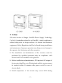
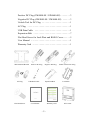
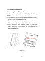
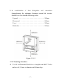
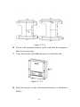
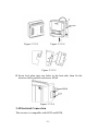
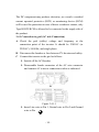
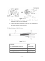
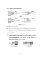
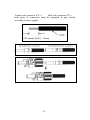
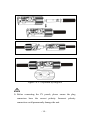
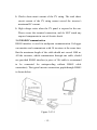
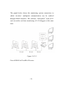
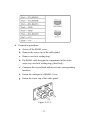
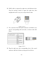
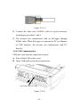
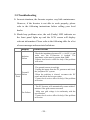
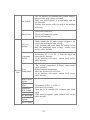
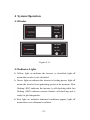
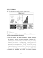
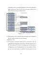
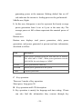
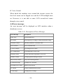
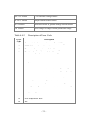
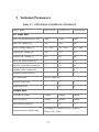
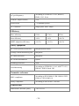
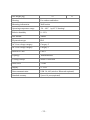
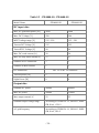
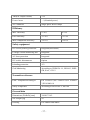
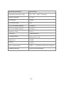
User Manual GOODWE SS SERIES Table of Contents 1 Symbols . . . . . . . . . . . . . . . . . . . . . . . . . . . . . . . . . . . . . 01 2 Safety . . . . . . . . . . . . . . . . . . . . . . . . . . . . . . . . . . . . . . . 02 3 Installation . . . . . . . . . . . . . . . . . . . . . . . . . . . . . . . . . . . 04 3.1 Mounting Instruction . . . . . . . . . . . . . . . . . . . . . . . . . 04 3.2 Unpacking . . . . . . . . . . . . . . . . . . . . . . . . . . . . . . . . . 04 3.3 Equipment Installation . . . . . . . . . . . . . . . . . . . . . . . . 06 3.4 Electrical Connection . . . . . . . . . . . . . . . . . . . . . . . . . 09 3.5 Troubleshooting . . . . . . . . . . . . . . . . . . . . . . . . . . . . . 20 4 System Operation . . . . . . . . . . . . . . . . . . . . . . . . . . . . . . 23 4.1 Display . . . . . . . . . . . . . . . . . . . . . . . . . . . . . . . . . . . 23 4.2 Indicator Lights . . . . . . . . . . . . . . . . . . . . . . . . . . . . . 23 4.3 LCD display . . . . . . . . . . . . . . . . . . . . . . . . . . . . . . . 24 4.4 Error Message . . . . . . . . . . . . . . . . . . . . . . . . . . . . . . 30 5 Technical Parameters . . . . . . . . . . . . . . . . . . . . . . . . . . . 33 GW1500-SS GW2000-SS GW3000-SS . . . . . . . . . . . . . . 33 GW4000-SS GW4600-SS . . . . . . . . . . . . . . . . . . . . . . . . 36 6 Certificates . . . . . . . . . . . . . . . . . . . . . . . . . . . . . . . . . . . 39 7 Warranty . . . . . . . . . . . . . . . . . . . . . . . . . . . . . . . . . . . . 40 7.1 Warranty Period . . . . . . . . . . . . . . . . . . . . . . . . . . . . . 40 7.2 Warranty Card . . . . . . . . . . . . . . . . . . . . . . . . . . . . . . 40 7.3 Warranty Conditions . . . . . . . . . . . . . . . . . . . . . . . . . 40 7.4 Scope of Warranty . . . . . . . . . . . . . . . . . . . . . . . . . . . 41 8 Contact . . . . . . . . . . . . . . . . . . . . . . . . . . . . . . . . . . . . . . 42 1 Symbols Caution! - Failure to observe a warning indicated in this manual may result in minor or moderate injury. Danger of high voltage and electric shock! Danger of hot surface! Product should not be disposed as normal household waste. This side up- The package must always be transported, handled and stored in such a way that the arrows always point upwards. Components of the product can be recycled. Fragile-The package/product should be handled carefully and never be tipped over or slung. Stack limitation-6 or 7 units of identical packages that may be stacked in maximum. Keep dry – The package/product must be protected from excessive humidity and must accordingly be stored under cover. CE Mark Residual voltage exists in the inverter; the inverter cannot be maintained within 5 minutes until the capacitor is fully discharged. -1- 2 Safety SS series inverter of Jiangsu GoodWe Power Supply Technology Co.,Ltd. ( hereinafter referred to as GoodWe ) strictly conforms to related safety rules in design and test. As electric and electronic equipment, Safety Regulation shall be followed during installation and maintenance. Improper operation may bring severe damage to the operator, the third party and other properties. The installation and maintenance of the inverters must be performed by qualified personnel only in compliance with national and local standards and regulations. Before installation and maintenance, DC input and AC output of the inverter should be cut off beforehand and the inverter cannot be touched within 10 minutes after power cut-off in case of electric shock. Partial temperature of the inverter may exceed 60℃ during -2- operation, please do not touch in case of scalding. All electric installation should conform to local electric standard and permission has to be obtained from local power supply department before synchronization by qualified personnel. Children must be kept away from inverters. Please do not open the front cover of inverter. Apart from wiring terminal, touching or changing components without authorization may cause damage to people and inverters. GoodWe may deny the obligation of warranty service accordingly. Static electricity may damage electronic components and proper measures shall be adopted to avoid static electricity. The output voltage of proposed PV array should be lower than the inverter maximum rated input voltage; otherwise, GoodWe will not undertake any obligations and warranty services. -3- 3 Installation 3.1 Mounting Instruction A In order to achieve optimal performance, the ambient temperature should be lower than 45 °C. B For the convenience of checking the LCD display and possible maintenance activities, please install the inverter at eye level. C Inverters should NOT be installed near inflammable and explosive items. Any electro-magnetic equipment should be kept away from installation site. D Product label and warning symbol shall be clear to read after installation. 3.2 Unpacking When you receive GoodWe inverter, please check if there is any visible external damage on the inverter or any accessories. Please also check if there is anything missing according to the list below. Inverter . . . . . . . . . . . . . . . . . . . . . . . . . . . . . . . . . . . . 1 Wall-mounted bracket . . . . . . . . . . . . . . . . . . . . . . . . . 1 Lock Plate . . . . . . . . . . . . . . . . . . . . . . . . . . . . . . . . . . 1 Positive DC Plug (GW1500-SS) . . . . . . . . . . . . . . . . . . 1 Negative DC Plug (GW1500-SS) . . . . . . . . . . . . . . . . . 1 Positive DC Plug (GW2000-SS / GW3000-SS) . . . . . . . 2 Negative DC Plug (GW2000-SS / GW3000-SS) . . . . . . 2 -4- Positive DC Plug (GW4000-SS / GW4600-SS) . . . . . . . 3 Negative DC Plug (GW4000-SS / GW4600-SS) . . . . . . 3 Unlock Tool for DC Plug . . . . . . . . . . . . . . . . . . . . . . . 1 AC Plug . . . . . . . . . . . . . . . . . . . . . . . . . . . . . . . . . . . 1 USB Data Cable . . . . . . . . . . . . . . . . . . . . . . . . . . . . . 1 Expansion Bolt . . . . . . . . . . . . . . . . . . . . . . . . . . . . . . 7 Flat Head Screw for Lock Plate and RS485 Cover. . . . . . 5 User Manual . . . . . . . . . . . . . . . . . . . . . . . . . . . . . . . . 1 Warranty Card . . . . . . . . . . . . . . . . . . . . . . . . . . . . . . . 1 Wall-mounted Bracket AC Plug Flat Head Screw Positive DC Plug USB Data Cable Negative DC Plug Expansion Bolt User Manual Warranty Card -5- Unlock Tool for DC Plug Lock Plate PV inverter 3.3 Equipment Installation 3.3.1 Selecting the installation position Installation position should be selected based on the following aspects: The installation method and mounting location must be suitable for the inverter's weight and dimensions. Mount on a solid surface. Select a well ventilated place sheltered from direct sun radiation. Install vertically or tilted backward by max 15°. The device cannot be installed with a sideways tilt. The connection area must point downwards. Figure 3.3.1-1 -6- In consideration of heat dissipation and convenient dismantlement, the minimum clearances around the inverter should be no less than the following value: Upward . . . . . . . . . . . . . . . . . . . . . . . . . . . . . . . 300mm Downward . . . . . . . . . . . . . . . . . . . . . . . . . . . . 500mm Front . . . . . . . . . . . . . . . . . . . . . . . . . . . . . . . . 300mm Both sides . . . . . . . . . . . . . . . . . . . . . . . . . . . . . 200mm Figure 3.3.1-2 3.3.2 Mounting Procedure A Use the wall-mounted bracket as a template and drill 7 holes on the wall, 10 mm in diameter and 80 mm deep. -7- Figure 3.3.2-1 B Fix the wall mounting bracket on the wall with the expansion bolts in accessory bag. C Carry the inverter by holding the groove on the heat sink. Figure 3.3.2-2 D Place the inverter on the wall-mounted bracket (as illustrated below). -8- Figure 3.3.2-3 Figure 3.3.2-4 Figure 3.3.2-5 E Insert lock plate into two holes in the heat-sink, then fix the inverter with a padlock and screw M3x8 Figure 3.3.2-6 3.4 Electrical Connection The inverter is compatible with RCD and RCM. -9- The DC component may produce electricity; as a result, a residual current operated protective (RCD) or monitoring device (RCM) will be used for protection in case of direct or indirect contact, only Type B RCD/RCM is allowed to be connected to the supply side of the product. 3.4.1 Connection to grid (AC side Connection) A Check the grid (utility) voltage and frequency at the connection point of the inverter. It should be 230VAC (or 220VAC), 50/60Hz, and single phase. B Disconnect the breaker or fuse between PV-Inverter and utility. C Connect the inverter to the grid as follows: Switch off the AC Breaker. Disassemble female connector of the AC wire connector and connect AC wires to connection socket as indicated. Figure 3.4.1-1 Insert Line wire to Pin 1, Neutral wire to Pin 2 and Ground wire to Pin - 10 - Figure 3.4.1-2 After fastening all screws, reassemble the female connector of the AC wire connector. Connect the female connector of the AC wire connector to the Male connector on the inverter. D Specifications of the AC wires: Figure 3.4.1-3 Depiction Size A External diameter of the wire 12mm-25mm B Sectional area of conducting materials Max.6mm2 C Length of bare wire Approx.10mm - 11 - E AC output connection diagram Figure 3.4.1-4 3.4.2 DC side connection A Make sure the maximum open circuit voltage (Voc) of each PV string does not exceed the inverter input voltage Vmax under any condition. B Use Multi-contact connectors for PV array terminals. C Connect the positive and negative terminals of the PV panel to corresponding terminals on the Inverter. The DC terminal on each Inverter can bear 20A DC current. - 12 - Female side connector (PV+) Male side connector (PV-) both types of connectors must be equipped in pair strictly according to above graphs - 13 - Figure 3.4.2-1 Separated by Ring tool Before connecting the PV panels, please ensure the plug connectors have the correct polarity. Incorrect polarity connection could permanently damage the unit. - 14 - Checks short-circuit current of the PV string. The total shortcircuit current of the PV string cannot exceed the inverter’s maximum DC current. High voltage exists when the PV panel is exposed to the sun. Please secure the terminal connection, and do NOT touch any exposed components in case of electric shock. 3.4.3 RS485 Communication RS485 interface is used for multipoint communication. EzLogger can monitor and communicate with 50 inverters at the same time. But the maximum length of the cable should not exceed 1000 m. All the inverters, which communicate through one cable, should use provided RS485 interface (a piece of 10# cable is recommend to be connected for waterproofing without RS485 cable connection). The typical inverter connection graph through RS485 is shown below. Figure 3.4.3-1 - 15 - The graph below shows the monitoring system connection, in which inverters’ multipoint communication can be realized through RS485 interface. The software “EzExplorer” used in PC end can realize real-time monitoring of 16 EzLoggers at the same time. Figure 3.4.3-2 Pins of RS485 of GoodWe SS series: - 16 - A Connection procedure: a. Screw off the RS485 cover; b. Remove the screw cap of the cable gland; c. Remove one-hole sealing ring; d. Put RS485 cable through the components in this order: screw cap, one-hole sealing ring, gland body; e. Compress the crystal head and insert it into corresponding interface; f. Fasten the waterproof of RS485 Cover; g. Fasten the screw cap of the cable gland. Figure 3.4.3-3 - 17 - B RS485 cable is composed by eight wires with different colors. Chop the envelope outside to expose the eight wires, then straighten the end of every wire, and put them in order. Figure 3.4.3-4 C The connection between crystal connectors and RS485 wires must be corresponding with each other, as shown in the table below. Figure 3.4.3-5 D Plug the eight wires into corresponding slots of the crystal connector, and then fix them up using special tool below. - 18 - Figure 3.4.3-6 E Connect the other end of RS485 cable to crystal connector according to procedure 3 and 4. F The inverter can communicate with an EzLogger through RS485 cable. When EzLogger is connected to PC via Ethernet or USB interface, the inverter can communicate with PC directly. 3.4.4 USB Communication USB data cable must be connected as below A Take off the USB socket cover B Insert USB cable as the arrow pointed out Figure 3.4.4-1 - 19 - 3.5 Troubleshooting In most situations, the Inverter requires very little maintenance. However, if the Inverter is not able to work properly, please refer to the following instructions before calling your local dealer. Should any problems arise, the red (Faulty) LED indicator on the front panel lights up and the LCD screen will display relevant information. Please refer to the following table for a list of error message and associated solutions. Display Possible actions Isolation Failure 1. Check the impedance between PV (+) & PV (-) and make sure the PV-Inverter is earthed. The impedance value must be greater than 2M. 2. Contact local service office for help if the problem still exists. Ground I System Failure Fault 1. The ground current is too high. 2. Unplug the inputs from the PV generator and check the peripheral AC system. 3. When the problem is cleared, reconnect the PV panel and check the Inverter status. 4. Contact local service office for help if the problem still exists. Vac Failure 1. The PV Inverter will automatically restart within 5 minutes if the grid returns to normal. 2. Make sure grid voltage is in conformity with the specification. 3. Contact local service office for help if the problem still exists. - 20 - Fac Failure 1. The PV Inverter will automatically restart within 5 minutes if the grid returns to normal. 2. Make sure grid frequency is in conformity with the specification. 3. Contact local service office for help if the problem still exists. Utility Loss 1. Grid is not connected. 2. Check grid connection cables. 3. Check grid usability. PV Over Voltage 1. Check whether the PV open voltage is higher or too close to the maximum input voltage. 2. If the problem still exists when PV voltage is less than the maximum input voltage, contact local service office for help. Consistent Failure 1. Disconnect PV (+) or PV (-) from the input and restart the PV Inverter. 2. If the problem still exists, contact local service office for help. 1. The internal temperature is higher than normal value specified. Over 2. Reduce ambient temperature. Inverter Temperature 3. Move the inverter to a cool place. fault 4. If the problem still exists, contact local service office for help. Relay-Check Failure DC Injection High EEPROM R/W Failure SCI Failure DC Bus High Ref 2.5V Failure GFCI Failure 1. Disconnect all PV (+) or PV (-). 2. Wait for a few seconds. 3. After the LCD switches off, reconnect and check again. 4. If the message appears again, contact local service office for help. - 21 - If there is no display on the panel, please check PV-input connections. If the voltage is higher than 125V, contact local service office for help. When sunlight is insufficient, the PV Inverter may continuously start up and shut down automatically due to insufficient power generated by the PV panel. If the problem remains, please contact the local service office. - 22 - 4 System Operation 4.1 Display Figure 4.1-1 4.2 Indicator Lights Yellow: light on indicates the inverter is electrified; light off means the inverter is not electrified. Green: light on indicates the inverter is feeding power; light off means the inverter is not generating power at the moment. Slow flicking (1HZ) indicates the inverter is self-checking while fast flicking (5HZ) indicates inverter finishes self-checking and is ready for grid integration. Red: light on indicates abnormal conditions appear; light off means there is no abnormal condition. - 23 - 4.3 LCD Display A The schematic of display screen is shown below: Figure 4.3-1 B Display area Display area is divided into top area, middle area and bottom area. Top area: displaying status information. This area displays the status information. “Waiting” indicates the inverter is standby for power generation; “Checking 30S” (checking time based on safety varies from country to country) indicates the inverter is self-checking, counting down and preparing for power generation; “Normal” indicates the inverter is generating power; if any condition of the system is abnormal, the screen will display error message, please refer to Table 5.4-1. Through key operation, the screen can display different - 24 - information such as operation parameters and power generation status in this area. There are two levels of menus, and the flow chart of first level menu is shown below: Figure 4.3-2 Menu display can be controlled by pressing the key; Holding the key for a while will enter into the submenu. Middle area, Left: The electrical connection status on DC side and AC side are represented by dashed line and full line. Flashing dashed line on DC side indicates PV panel is feeding power to the inverter; Nothing shows on AC side means grid is not available; full line on AC side means grid is available, but the inverter is not - 25 - generating power at the moment; flashing dashed line on AC side indicates the inverter is feeding power to the grid network. Middle area, Right: In this area, histogram is used to represent the hourly average power generation from 4 a.m. to 8 p.m. at the same day. The average power at full column represents the nominal power of system. Bottom area: Bottom area displays total power generation, daily power generation, and power generated at present and time information, described as follow: Part Description E-TOTAL Gross power generated from the first time use of inverter. The initial unit is “kWh”; When power generation exceeds 9999.9kWh, the unit changes to “MWh”. E-DAY Power generated the same day POWER Instant power generation of the system TIME Current system time C Key operation: There are 2 modes of key operation: Short press, Long press 2S. D Key operation and LCD description: Key operation is mainly for language and time setting. Clients can also find the information they concern through key - 26 - operation. The menu in LCD display area has two levels, you can hold the key to enter second-level menu; long press the key 2S to lock the current interface if there is no second-level menu. In all levels of menu, it will automatically enter the first item of the first level menu if no action is taken within 20S, meanwhile, the modified data will be stored into internal memory. E Menu Introduction When PV panel is feeding power to the inverter, the screen shows the first-level menu. Initial display is the first interface of the first-level menu and the interface displays current state of the system. It shows “Waiting” in the initial state; it shows “Normal” during power generation mode; if there is something wrong with the system, error message is shown. Please see 4.4 for fault code. Short press the key once to enter Vpv menu which displays the PV voltage in“V”. Short press the key once to enter Ipv menu which displays the PV current in“A”. Short press the key once to enter Vac menu which displays the grid voltage in“V”. Short press the key once to enter Iac menu which displays the grid current in“A”. Short press the key once to enter Frequency menu which displays the grid frequency in“Hz”. - 27 - Long press the key for 2S will enter the second-level menu of error detection history, the last three inverter error records will be shown by short pressing the key in the second-level menu, which includes error code (ECODEXX), error time (e.g. 201103-16 15:30 ). Error code can be found in Table. 4.4-2. The LCD backlight will be off without any operation within 20S, LCD display will automatically return to main menu. Short press the key once into ModelName menu under which submenu can be found. Short press the key once to enter the software version menu which shows the current software version used. The LCD backlight will be off without any operation within 20S, LCD display will automatically return to main menu. Short press the key once to enters language display menu. Press the button for 2S to enter the second level menu. The circulatory submenu including two languages can be found. The language can be chosen by short pressing the key. The inverter will store the chosen language without any action within 20S and LCD display will automatically return to main menu when the backlight is off. Short press the key once to enter time display menu which is used to display the current time. Long press the key for 2S to enter the submenu to set the time of the inverter. The initial display is “000000 00:00”, in which the first two numbers represent the year (e.g. 00~99); the third and fourth number - 28 - represent the month (e.g. 01~12); the fifth and the sixth number represent the date (e.g. 01~31),the seventh number will be flicking firstly and number“0”, “1”, “2”can be chosen by shortly pressing the button. Then hold the key for 2 to set the eighth number. Number 0-9 can be chosen by short pressing the key. “Minute” can be set with the same steps as the “hour”. The inverter will store the time without any action in 20S and LCD will automatically return to main menu when the backlight is off. Long press the key 2S in the menu with no submenu, LCD will display “Lock” and then this menu will be locked after 1S. In order to check Vpv value, enter Vpv menu first, long press the key 2S, the screen will display “Lock” first and Vpv value afterwards. The locked menu can only be unlocked under system mode switching, fault occurrence or key operation. F Normal Start and Operation Display. When the input voltage reaches inverter turn-on voltage, LCD starts to work, the yellow light is on, LCD displays “waiting”, more information will be displayed within a few seconds. If the inverter is connected to the grid, “Checking 30” will be shown up in 2S, counting down from 30S, when it shows “00S” you can hear the reply triggered 4 times, LCD displays “Normal” afterwards. The instant power output will be shown at the left bottom of LCD. - 29 - G Voice Control When knock the machine cover around the inverter screen, the first-level menu can be flipped over and the LCD backlight turns on. However, it is not able to enter LCD second-level menu through voice control. 4.4 Error message An error message will be displayed on LCD interface when a disturbance occurs. Table 4.4-1 Description of Error Message Error message Description Utility Loss Grid disconnected Fac Failure Grid frequency no longer within permissible range Consistent Failure Machine parameter consistent fault Device Failure Device internal fault PV Over Voltage Overvoltage at DC input Over Temperature Overtemperature on the case Isolation Failure Ground insulation impedance is too low Ground I Failure Overhigh ground leakage current Relay-Check Failure Relay self-checking failure DC Injection High Overhigh DC injection EEPROM R/W Failure Memory chip failure SCI Failure Internal communication failure DC Bus High Overhigh BUS voltage - 30 - Ref 2.5V Failure 2.5V reference voltage failure AC HCT Failure Output current sensor failure GFCI Failure Detection circuit of ground leakage current failure Vac Failure Grid voltage no longer within permissible range Table 4.4-2 Error Code 01 Description of Error Code Description Communication between microcontrollers is failing 02 EEPROM cannot be read or written 03 The master-frequency is out of tolerable range 04 The slave-frequency is out of tolerable range 05 NA 06 NA 07 Relay is Fail 08 NA 09 Different value between Master and Slave for grid voltage 10 Different value between Master and Slave for grid frequency 11 NA 12 Different value between Master and Slave for Fac, Uac 13 The DC injection check for grid Current is fail 14 Isolation resistance of PV-plant out of tolerable range 15 Master-grid voltage measurement-value out of tolerable range 16 Fan Lock 17 Pv input voltage is over the tolerable maximum value 18 NA 19 Over temperature fault 20 NA - 31 - 21 Dc bus fault 22 Ground current is too high 23 Grid voltage =0 24 NA 25 Device Fault 26 Dc Bus voltage is too high. 27 NA 28 Different value between Master and Slave for GFCI 29 30 Different value between Master and Slave for output DC current The 2.5V reference inside are abnormal 31 The DC output sensor is abnormal 32 The GFCI detecting circuit is abnormal - 32 - 5 Technical Parameters Table 5.1 GW1500-SS, GW2000-SS, GW3000-SS Model Name GW1500-SS GW2000-SS GW3000-SS Max. PV-generator power [W] 1800 2300 3200 Max. DC Voltage [V] 450 500 500 MPPT voltage range [V] 125~450 125~450 125~450 Turn on DC Voltage [V] 125 125 125 Turn off DC Voltage [V] 90 90 90 Max. DC work current [A] 12 15 18 Max.PV array short current[A] 15 18 20 Number of DC connection 1 2 2 Number of MPP trackers 1 1 1 DC-connection MC IV Connector Turn on power [W] 5 5 5 Night power[W] 0 0 0 Nominal AC power 1500W 2000W 3000W Max.AC power 1650W 2000W 3000W Max.output current[A] 8 10 15 DC input data Output data Nominal output voltage range According to VDE0126-1-1/A1, RD1663, ENEL, G83, SAA - 33 - AC grid frequency According to VDE0126-1-1/A1, RD1663, ENEL, G83, SAA THD(AC output current) <1% Power factor ~1(Nominal power) AC Connector Single phase with Clamps Efficiency Max. efficiency 97.0% 97.0% 97.0% Euro efficiency >96% >96% >96.5% MPPT adaptation efficiency >99.5% >99.5% >99.5% Safety equipment DC reverse polarity protection Integrated(with diode) Leakage current monitoring unit Integrated AC short protection Integrated DC switch-disconnector Option Islanding protection AFD Grid Monitoring According to VDE0126-1-1/A1, AS4777.1/2/3, RD1663, ENEL Guied, G83 Normative reference EMC compliance According to EN 61000-6-1,EN 61000-6-2,EN 61000-6-3,EN 61000-6-4 Safety compliance According to IEC62109-1, AS3100 General data Dimensions (WxHxD) [mm] 330*350*125 - 34 - Net Weight [kg] 12 13 Housing For outdoor and indoor Mounting information Wall bracket Operating temperature range -20~60°C(up 45°C derating) Relative humidity 0~95% Site altitude 2000m IP protection type IP65 AC Over voltage category Category 2 DC Over voltage category Category 3 Protective Class Class 1 Topology Transformerless Cooling concept Nature Convection Noise level <25dB Display 4’’ LCD Data communication USB 2.0; 485(wireless /Bluetooth optional) Standard warranty 5years/10 years(optional) - 35 - Table 5.2 GW4000-SS, GW4600-SS Model Name GW4000-SS GW4600-SS DC input data Max. PV-generator power [W] 4600 5400 Max. DC Voltage [V] 580 580 MPPT voltage range [V] 125~550 125~550 Turn on DC Voltage [V] 125 125 Turn off DC Voltage [V] 90 90 Max. DC work current [A] 20 20 Max.PV array short current[A] 27 27 Number of DC connection 3 3 Number of MPP trackers 1 1 DC-connection MC IV or HC IV-connector Turn on power [W] 5 5 Night Power [W] 0 0 Nominal AC power 4000W 4600W Max.AC power 4400W 5100W Max.output current[A] 22 25 Nominal output voltage range According to VDE0126-1-1, RD1663, ENEL, GB, SAA, G59-2 AC grid frequency According to VDE0126-1-1, RD1663, ENEL, GB, SAA, G59-2 Output data - 36 - THD(AC output current) <2% Power factor ~1(Nominal power) AC Connector Single phase With Clamps Efficiency Max. efficiency 97.8% 97.8% Euro efficiency >97.4% >97.4% MPPT adaptation efficiency >99.5% >99.5% Safety equipment DC reverse polarity protection Integrated(with diode) Leakage current monitoring unit Integrated AC short protection Integrated DC switch -disconnector Option Islanding protection AFD Grid Monitoring According to VDE0126-1-1, RD1663, ENEL, GB, SAA, G59-2 Normative reference EMC- compliant according to EN 61000-6-1,EN 61000-6-2,EN 61000-63,EN 61000-6-4 Safety compliance According to IEC62109-1, AS3100 General data Dimensions (WxHxD) [mm] 390*417*142 Net Weight [kg] 18 Housing For outdoor and indoor - 37 - Mounting information Wall bracket Operating temperature range -20~60°C(up 45°C derating) Relative humidity 0~95% Site altitude 2000m IP protection type IP65 AC Over voltage category Category 2 DC Over voltage category Category 3 Protective Class Class 1 Topology Transformerless Cooling concept Natural convection Noise level <25dB Display 4”LCD Data communication USB2.0; 485(Wireless/Bluetooth optional) Standard warranty 5years/10 years(optional) - 38 - 6 Certificates - 39 - 7 Warranty 7.1 Warranty Period GoodWe provides standard warranty period of 5 years for SS series products (Warranty period begins from the date on purchase invoice). Additional provision will be subject to contract. 7.2 Warranty Card Warranty card and purchase invoice should be properly kept within product warranty period. Meanwhile, the nameplate on products shall be clear to read. Otherwise GoodWe may deny the warranty service or only provide paid service. 7.3 Warranty Conditions According to GoodWe product description and instruction, if a device becomes defective within warranty period, and it is proved that further functional performance is impossible due to product quality problem, the device will be, as selected by GoodWe: A Return to the factory for maintenance; B Onsite maintenance; C Products Replacement (if the original model has stopped in production, GoodWe will provide a replacement device of equivalent value according to model and age.). - 40 - 7.4 Scope of Warranty Warranty declaration is excluded in the following situations: Products or fittings exceed warranty period (exclude the warranty extension agreement signed beforehand). Fault or damage due to improper operation without following user manual, product instruction, and relevant safety regulations. Insufficient ventilation of the unit Fault or damage due to improper installation, repair, change or removal by persons who are not authorized by GoodWe. Fault or damage due to unpredictable accidental factors, human errors or force majeure. Fault or damage which is not caused due to products quality problem. - 41 - 8 Contact If you have any enquiries or technical problems concerning GoodWe SS series inverter, please contact our customer services. Add: No.189 Kun Lun Shan Road, Suzhou New District, Jiangsu, China (Jiangsu GoodWe Power Supply Technology Co., Ltd.) Tel: + 86 512 6239 6771 Fax: + 86 512 6239 7972 E-mail: [email protected] Website: www.goodwe.com.cn - 42 -