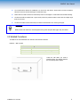
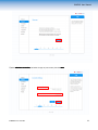
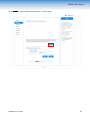
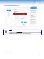
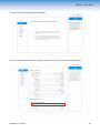
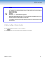
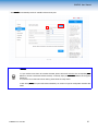
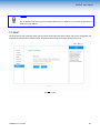
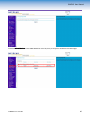
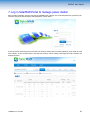
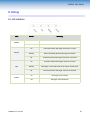
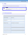
1
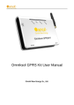
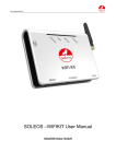
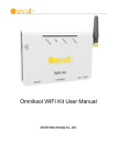
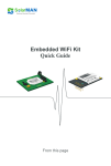
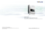
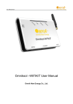
USER MANUAL
External Data Logger
WiFi Kit S-WE01S
Version 1.0
www.solarmanpv.com
S-WE01S User Manual
1. GENERAL INFORMATION ........................................................................................................................................................ 2
1.1 SYMBOL DESCRIPTION ................................................................................................................................................. 2
2. INSTRUCTIONS & NOTES ...................................................................................................................................................... 2
2.1 INSTRUCTIONS .............................................................................................................................................................2
2.2 NOTES ......................................................................................................................................................................... 2
3. INSTALLATION ....................................................................................................................................................................... 3
3.1 PACKING LIST .............................................................................................................................................................. 3
3.2 LOCATION /PLACEMENT ................................................................................................................................................3
3.3 DETAILED PROCEDURES .............................................................................................................................................. 4
4. CONNECTION TO INVERTER AND POWER .............................................................................................................................. 7
4.1 INTERFACE , BUTTON AND CABLE INTERFACE ............................................................................................................. 7
4.2 CONNECTION ............................................................................................................................................................... 8
4.2.1 CONNECTION TO SINGLE INVERTER .................................................................................................................8
4.2.2 CONNECTION TO MULTIPLE INVERTERS ........................................................................................................... 8
4.3 CONFIRM CONNECTION ................................................................................................................................................9
5. CONNECT THE DATA LOGGER TO THE SERVER .................................................................................................................... 10
5.1 CONNECTION VIA SETUP WIZARD............................................................................................................................ 10
5.1.1 PREPARATIONS ...............................................................................................................................................10
5.1.2 OBTAIN AN IP OR DNS SERVER ADDRESS AUTOMATICALLY .........................................................................10
5.1.3 SET NETWORK CONNECTION TO THE DATA LOGGER ..................................................................................... 12
5.1.4 NETWORK CONFIGURATION OF THE DATA LOGGER ....................................................................................... 12
5.2 NETWORK SETTING ON WIRELESS INTERFACE ......................................................................................................... 25
5.3 DEVICE SETTING ON CABLE SETTING INTERFACE ..................................................................................................... 33
5.4 DEVICE SETTING ON ADVANCED SETTING INTERFACE ..............................................................................................34
5.5 UPGRADE ................................................................................................................................................................... 42
5.6 RESTART ....................................................................................................................................................................43
5.7 RESET ........................................................................................................................................................................44
5.8 OBTAIN THE NEW IP ADDRESS................................................................................................................................. 45
6. REGISTER
7. LOG
IN
ON
SOLAR MAN PORTAL .....................................................................................................................................47
SOLAR MAN PORTAL
TO MANAGE POWER STATION ................................................................................................49
8. DEBUG ................................................................................................................................................................................. 50
8.1 LED INDICATION ...................................................................................................................................................... 50
8.2 TROUBLE SHOOTINGS ................................................................................................................................................51
8.3 RESET ........................................................................................................................................................................51
9. SCRAP ..................................................................................................................................................................................52
10. TECHNICAL
PARAMETERS ...................................................................................................................................................52
11. CONTACT ...........................................................................................................................................................................53
M-WE01S-V1.0-0713-EN
1
S-WE01S User Manual
1. General information
This manual is intended to assist users in the installation, connection and commissioning of the PV data logger WiFi Kit
S-WE01S. We will not be liable for any damage caused by non-observance of the instructions of this manual.
This manual should be placed at a safe place to ensure that it is available when needed. If this manual is lost, an up-to-date
electronic version can be obtained from SolarMAN customer service.
1.1 Symbol description
Warning
This symbol indicates potential hazard to personal or device. Users should set the device under the instruction of
this manual, otherwise a personal injury or device damage might occur.
Attention/Notice
This symbol indicates the issues that users should take account into. Users should pay attention to the notice
while setting the device, otherwise a device damage might occur.
2. Instructions & Notes
Please read the instructions and notes carefully, otherwise personal injury or device damage might occur if not avoided.
2.1 Instructions
�All installation work must be operated by professional workers.
�Please turn the power off during device installation and connection.
�Please do not remove the cover of the device.
�Please make sure that all operations during the device setting are in compliance with local laws and regulations.
2.2 Notes
�Damaged device must be replaced immediately. Please contact the manufacturer for repair or replacement, if the
device is still within warranty period. Self maintenance or continuous working is not accepted.
�The device must be operated with certain power supply. The working voltage should be within specified range.
M-WE01S-V1.0-0713-EN
2
S-WE01S User Manual
�The device meets the requirements of protection class IP21 and is therefore only suitable for installation in dry, clean
spaces. For outdoor installation or operation under adverse conditions the device must be mounted in an additional
casing that meets the requirements of the required protection class.
�Please keep the device away from children.
�Please turn off the power when the device is not working for a long time.
3. Installation
3.1 Packing list
Please check the packing list carefully before installation . If a device defect, accessory lacing, or other problem exit, please
contact manufacturer immediately.
A
B
C
D
E
Pic. 1
Code.
Quantity
Description
Model
A
1
External data logger
WiFi Kit S-WE01S
B
1
Power adapter
FY0502000
C
2
Expandable rubber hoses
--
D
2
Screws
--
E
1
Quick guide
--
3.2 Location/Placement
In order to keep the device away from damage and working normally, following conditions should be met when choosing
the installation place.
�
The device cannot be installed outdoor or in some place which is dusty, damp or full of corrosive vapors. In
addition, direct sunshine, vibration and pressure should be avoided.
�
The ambient temperature of the installation location must be within the range between -10℃ and +65 ℃.
M-WE01S-V1.0-0713-EN
3
S-WE01S User Manual
�
The communication distance for RS485/422 is no more than 1000 meters. Please make sure that the distance
between the inverter and the data logger is within this range.
�
Please make sure that the device is located away from the crucial pipes or wires behind the wall before drilling.
�
The device should be installed near a power outlet, which can provide 50-60Hz current with the voltage range
from 100V to 240V.
�
The device should be located 10cm away from metal in each direction as to ensure good signal.
Attention
Metal products can weaken the electromagnetic waves, please keep the data logger away from metal.
3.3 Detailed Procedures
This WiFi Kit can be installed with two methods: wall-mounted or flatwise.
Method 1:Wall mounted
Tools
Purpose
Impact Drill
Drill holes
Rubber hammer
Hammer the screw into expendable pipes.
Screwdriver
Screw
1.Mark the wall where you need to
install the device. The distance between
the two marking spots is 69mm.
M-WE01S-V1.0-0713-EN
4
S-WE01S User Manual
2. At each marking spot, drill a hole with
6mm in diameter and with the depth not
less than 30mm.
3. Hammer the plastic expandable pipe
into the hole with a rubber hammer.
4. Screw the two screws into the
expandable pipe, with the head of the
screw exposed outside the wall for
6mm.
M-WE01S-V1.0-0713-EN
5
S-WE01S User Manual
5.Hang the WiFi Kit on the screws, and
rotate the metal part of the antenna to
the desired direction manually.
Pic. 2
Method 2: Flatwise
Lay the device on flat ground, and rotate the metal part of the antenna to the desired direction.
Attention:
1. Only the metal part of the antenna is designed for rotating,please do not screw the plastic part, otherwise
a device damage might occur. To avoid device malfunction caused by antenna, please make sure that the
antenna is installed properly under the instruction of the manual.
2. In order to keep the device working normally,please make sure that the data logger will not be moved once
it has been installed in a suitable location.
M-WE01S-V1.0-0713-EN
6
S-WE01S User Manual
4. Connection to Inverter and Power
4.1 Interface, Button and Cable interface
Pic. 3 Interface and button
Pic. 4 Cable interface
M-WE01S-V1.0-0713-EN
7
S-WE01S User Manual
Device
WiFi Kit
Order
Color
RJ45
RS485
RS422
RS232
1
White Orange
Pin1
NC
NC
NC
2
Orange
Pin2
NC
NC
NC
3
White Green
Pin3
NC
RX+
RXD
4
Blue
Pin4
A
TX+
NC
5
White Blue
Pin5
B
TX-
NC
6
Green
Pin6
NC
RX-
TXD
7
White Brown
Pin7
GND
GND
GND
8
Brown
pin8
GND
GND
GND
4.2 Connection
Please use the cable with RJ45 connector on each head and the line order is T568B.
4.2.1 Connection to single inverter
1)
2)
3)
4)
Please turn the power off.
Plug the cable into the RS485/422/232 port on the inverter.
Plug the other head of the cable into the RS485/422/232 port of the data logger.
Connect the power adapter to the data logger and plug the adapter.
Pic. 5
4.2.2 Connection to multiple inverters
1)
2)
3)
4)
Please turn the power off.
Plug the cable into the RS485/422 port of a inverter.
Plug the other head of the cable into the RJ45 port of the second inverter.
String connect all the inverters you need to connect with the above method.
M-WE01S-V1.0-0713-EN
8
S-WE01S User Manual
5)
6)
Connect the first or last inverter in the string to the data logger with network cable.
Connect the data logger to power outlet with the power adapter, then turn on the power of the inverter.
Pic. 6
Warning
Please turn the power off before setting and connection. All connections must be finished and checked before
powering on, otherwise personal injury or device damage might occur.
4.3 Confirm connection
When all connections are completed and with the power on for about 1 minute, check the 4 LEDs. If POWER and STATUS are
permanently on, and LINK and 485/422 are permanently on or flashing, connections are successful. If any problems, please
refer to 8. Debug.
M-WE01S-V1.0-0713-EN
9
S-WE01S User Manual
5. Connect the data logger to the server
5.1 Connection via Setup Wizard
5.1.1 Preparations
Prepare a computer or device, e.g. tablet PC and smartphone, that enables WiFi.
5.1.2 Obtain an IP or DNS server address automatically
1)If WiFi function is available on your computer, you may see a icon of compute like this
,on the bottom of your
screen. Double click the icon, then click properties
M-WE01S-V1.0-0713-EN
10
S-WE01S User Manual
2)Double click Internet Protocol (TCP/IP)
3) Select Obtain an IP address automatically
automatically, and click OK
M-WE01S-V1.0-0713-EN
11
S-WE01S User Manual
5.1.3 Set network connection to the data logger
Refresh the wireless network list several times till the AP network shows on the list. Connect to the AP network.
Select wireless network of the data logging module, no passwords required as default. The network name consists of AP and
the serial number of the product
product. Then click Connect
Connect.
5.1.4 Network configuration of the data logger
Open a web browser, and enter 10.10.100.254
10.10.100.254, then fill in username and password, both of which are admin as default.
admin
admin
M-WE01S-V1.0-0713-EN
12
S-WE01S User Manual
5.1.4.1 Status Interface
After clicking OK
OK, the Status interface will display first. The device information of data logger, such as the device mode and
serial number, will display on this page.
5.1.4.2 Follow the setup wizard to start quick setting
Click Wizard to logon to the setup interface, and follow the setup wizard to start quick setting.
1 Click Start to begin quick setting
○
This setup wizard will assist you to complete the device setting within one minute.
M-WE01S-V1.0-0713-EN
13
S-WE01S User Manual
2 )Select Wireless connection
○
connection, and select the type of your inverter, then click Next
M-WE01S-V1.0-0713-EN
14
S-WE01S User Manual
You may select cable connection in this page, then skip to Step ⑥ on page 19.
Notice
1. The STA mode of wireless connection will be turned off by system automatically when you choose cable
network connection
2. Whether to keep the AP mode or wireless connection or not can be set by turning on or off the wireless
function
M-WE01S-V1.0-0713-EN
15
S-WE01S User Manual
3 Click Refresh to search available wireless networks, or add it manually.
○
M-WE01S-V1.0-0713-EN
16
S-WE01S User Manual
④Select the wireless network you need to connect, then click Next
Notice
1. If the signal strength (RSSI) of the selected network is <15%, which means unstable connection, please
adjust the antenna of the router, or use a repeater to enhance the signal.
2. This step will help you to connect the device to the desired WLAN. If you do not find your wireless router on
the network list, please click refresh or add it manually.
3. Please check your wireless router for the right encryption method and encryption algorithm.
4. If your wireless router does not broadcast the SSID, please set the desired wireless network in Wireless
interface on page 26.
M-WE01S-V1.0-0713-EN
17
S-WE01S User Manual
⑤Enter the password for the selected network, then click Next
The password is being verified, please wait for a while. If you have entered an invalid password or encryption method, an error
notice will pop up.
Notice:Please make sure you have entered the valid password.
M-WE01S-V1.0-0713-EN
18
S-WE01S User Manual
⑥Select Enable to obtain an IP address automatically, then click Next
Notice
Most systems support the function of DHCP to obtain IP address automatically. Please add it manually if your
router does not support such function.
M-WE01S-V1.0-0713-EN
19
S-WE01S User Manual
⑦ Enhance security settings of the device by selecting any options as follows, then click Next
� Option 1. Hide AP
Notice
If you choose to hide AP
AP, the SSID of the AP network of your WiFi Kit will be invisible on the wireless network
list. Please enter the SSID manually when you need to connect to AP next time.
M-WE01S-V1.0-0713-EN
20
S-WE01S User Manual
�
Option 2. Change the encryption mode for AP
Notice
If you wish to change the encryption mode of the AP network, you will need to enter the corresponding
encryption method and password before you connect to this WiFi Kit next time.
M-WE01S-V1.0-0713-EN
21
S-WE01S User Manual
�
Option 3. Change the user name and password for Web server
Notice
If you change the user name and password for the Web server, you will need to enter the new username and
password when you need to re-log on this server.
M-WE01S-V1.0-0713-EN
22
S-WE01S User Manual
⑧If setting is successful, the following page will display. Click OK to restart.
Notice
After you click OK, the system will restart automatically. Please wait for about 30s during restart.
M-WE01S-V1.0-0713-EN
23
S-WE01S User Manual
⑨If restart is successful, the following page will display.
⑩Re-log on the setting page after network setting is completed, and check the network status on Status page.
M-WE01S-V1.0-0713-EN
24
S-WE01S User Manual
Notice
1. After network setting is completed, the Wireless STA mode should be enabled and relative information of your
router will display on the interface automatically as follows. In addition, Remote server A should be pingable as
shown in the above graph.
Wireless STA mode: Enable
Router SSID:
Signal quality:*% (please refresh the page if it shows 0)
IP address:192.168.1.***(Please refresh the page if it shows 0.0.0.0)
Mac address:the Mac address of your local network
Network setting might be failed if it still shows 0 or 0.0.0.0 in the signal quality and IP address. Please try to reset
the network connection to the device according to the quick guide.
2. The IP address of the device may have changed. Please refer to chapter 5.8 to check the procedures to obtain
the new IP address.
5.2 Network setting on Wireless interface
5.2.1 Please make preparations according to 5.1.1 and 5.1.2 on page 10.
5.2.2 Click Wireless to log on the wireless interface and start configuration of the data logger.
M-WE01S-V1.0-0713-EN
25
S-WE01S User Manual
① click Search to automatically search for available wireless access point
Notice
1. If your wireless router does not broadcast the SSID, please click search and select the corresponding MAC
address to connect to the desired wireless network, or manually input your SSID MAC address and encryption
method,etc.
2. If you have not set this kind of device before, please follow the setup wizard.
3. After clicking Save
Save, the system will restart immediately. You need to re-login the configuration interface after
restart.
M-WE01S-V1.0-0713-EN
26
S-WE01S User Manual
②Click Refresh to search available wireless networks
③Select the wireless network you need to connect, then click OK
M-WE01S-V1.0-0713-EN
27
S-WE01S User Manual
If your wireless router does not broadcast the SSID, please set the desired wireless network according to the MAC
address..
Notice
This step will help you to connect the device to the desired WLAN. If you do not find your wireless router on the
network list, please refresh a few times or add it manually. To select the right encryption method and encryption
algorithm, please check your wireless router.
M-WE01S-V1.0-0713-EN
28
S-WE01S User Manual
Save.
④Click OK after it returns to the setting page. Enter the password for selected network, then click Save
M-WE01S-V1.0-0713-EN
29
S-WE01S User Manual
Notice: The password is being verified, please wait for a while. If you have entered an invalid password or encryption method,
an error notice will pop up.
M-WE01S-V1.0-0713-EN
30
S-WE01S User Manual
⑤If setting is successful, the following page will display.
Notice
1. The IP address of the device may have changed. Please refer the chapter 5.8 to check the procedures to
obtain the new IP address.
2. If you would like to enhance the security of this web server, please set this device via Setup Wizard.
M-WE01S-V1.0-0713-EN
31
S-WE01S User Manual
⑥Re-log on the setting page after network setting is completed,and check the network status on Status page.
Notice
1. After network setting is completed, the Wireless STA mode should be enabled and relative information of your
router will display automatically as follows. Remote server A should be pingable as shown in above graph.
Wireless STA mode: Enable
Router SSID:
Signal quality:*% (please refresh the page if it shows 0)
IP address:192.168.1.***(Please refresh the page if it shows 0.0.0.0)
Mac address:the Mac address of your local network
Network setting might be failed if it still shows 0 or 0.0.0.0 in the signal quality and IP address. Please try to reset
the network connection to the device according to the quick guide.
2.the IP address of the device may have changed. Please refer to chapter 5.8 to check the procedures to obtain
the new IP address.
M-WE01S-V1.0-0713-EN
32
S-WE01S User Manual
5.3 Device setting on Cable setting interface
If you would like to set cable network connection to this device, please connect the data logger to the router with a network
cable first.
1. Select Enable to obtain an IP address automatically, then click Save
Notice
1. This page will help you to configure cable network parameters if your device support cable network.
2. When you choose cable network connection, the STA mode of wireless connection will be turned off
automatically.
3. Whether to keep the AP mode of wireless connection or not can be set by turning on or off the wireless
function.
4. Most systems support the function of DHCP to obtain IP address automatically . Please add it automatically if
your router do not support such function.
M-WE01S-V1.0-0713-EN
33
S-WE01S User Manual
2. If saved successfully, the following page will display.
Notice
The IP address of the device may have changed. Please refer to chapter 5.8 to check the procedures to obtain
the new IP address.
3. Please refer to Step ⑩ in part 5.1 on page 24.
5.4 Device setting on Advanced setting interface
In Advanced setting, you can configure the parameters of the device. Please do not change the default settings unless guided
by professional staff, otherwise the parameters change may cause device malfunction,e.g. failure to log on the setting page,
no data transmission, etc.
1. Select working mode
M-WE01S-V1.0-0713-EN
34
S-WE01S User Manual
mode, then click Save
Save.
① Select your desired Working mode
Notice
1. The device usually works under data collection mode. You can select transparency mode if your device
supports this function.
2. When under transparency mode, the device with the connected device will communicate with remote
computer directly.
M-WE01S-V1.0-0713-EN
35
S-WE01S User Manual
After changing the setting, the device must be restarted. After restart, you will need to re-log on the configuration interface. It
is recommended to restart after all settings are completed.
2. Set remote server
After the network setting is completed, monitoring data will be transmitted to Server A as default. You can set other servers to
receive data in this page.
M-WE01S-V1.0-0713-EN
36
S-WE01S User Manual
① Enter the IP address or domain name and port number to add a new server,click Test to check the server status, then
click Save when setting is completed.
Notice
1.Your device can transfer data to several servers in the form of TCP/UDP if your device supports this function.
2. Please makes sure that the response to ping request function is enabled on the assigned server for receiving
data.
M-WE01S-V1.0-0713-EN
37
S-WE01S User Manual
After changing the settings, the device must be restarted. After restart, you will need to re-login the configuration
interface. It is recommended to restart after completing all configurations.
3. Port Setting
In this page, you can set the parameters for serial port and the internal web server of the data logger. After the network setting
of device is completed, all parameters will be loaded to corresponding columns automatically. Please do not change the default
settings, otherwise the parameters change may cause device malfunction.
① Set serial port
In this column, you can change the serial port parameters for the data logger. Any operation on this page should be
guided by professional engineer.
② Set internal server
In this column, you can change the serial port parameters for the data logger. Any operation on this page should be
guided by professional engineer.
M-WE01S-V1.0-0713-EN
38
S-WE01S User Manual
4. Set wireless access point
In this page, you can configure the parameters of the device when it works under Wireless access point mode. After the
network setting of device is completed, all parameters and encryption information of your network will be loaded into
corresponding columns automatically. Please do not change the default settings, otherwise the parameters change may cause
device malfunction.
① Set wireless access point
Parameters listed in the following columns are designed for setting the function of the device when it works under AP
mode. Information including network mode, network name, select channel and transmission power will be recognized by
the device automatically. If any parameters change is required, please follow the instructions by professional staff.
② Security setting for Wireless access point
Parameters listed in the following column are designed for setting the encryption method of the device. Setting in this
column should be operated under the instructions by professional staff.
(a)
Notice
If you wish to change the user name and password of the Web server, please enter the new username and
password when you need to re-log in this server.
M-WE01S-V1.0-0713-EN
39
S-WE01S User Manual
(b)
Notice
If you wish to change the encryption mode of the AP network, you will need to enter the corresponding
encryption method and password before you connect to this device next time.
③ Set LAN parameters
Parameters listed in the following columns are designed for changing the status of local area network which is
embedded in the device. Information including IP address and Subnet mask will be recognized automatically. Setting
for other functions should be guided by professional staff.
Notice
1. If a domain name changing is required, please enable the function to automatically obtain DNS server. Please
refer to chapter 5.2.2 to check the detailed procedures. or enter the information of IP address(DHCP gateway
setting).
2. After changing the settings, the device must be restarted. After restart, you will need to re-login the
configuration interface. It is recommended to restart after completing all configurations.
M-WE01S-V1.0-0713-EN
40
S-WE01S User Manual
5. After saved successfully, the following page will display. Click Restart
Restart.
Notice
After you click Restart, the system will restart automatically. Please wait for about 30s during restart.
M-WE01S-V1.0-0713-EN
41
S-WE01S User Manual
5.5 Upgrade
In this page,the firmware of device can be upgraded by uploading the update files from your local computer.
Click Browse to upload the firmware, then click Upload to start upgrade.
Notice
1. The firmware update should be operated during a shiny period among the day.
2. During upgrade, please make sure that the power and network connection between WiFi Kit and the router is
stable, and the WiFi signal is constantly good.
M-WE01S-V1.0-0713-EN
42
S-WE01S User Manual
5.6 Restart
The device can be restarted in this page. After restart, all settings you have made before shall be effective. It may takes 30s to
restart the device, and please read the notice on the page carefully before restart.
Click OK to restart the device
Rebooting successful. Please close this page automatically.
M-WE01S-V1.0-0713-EN
43
S-WE01S User Manual
Notice
The IP address of the device may have changed. Please refer to chapter 5.2.4.9 to check the procedures to
obtain the new IP address.
5.7 Reset
The device can be reset in this page. After reset, the device will be restored to factory setting, and all users’ configuration will
be deleted. It may takes 30s to reset the device, and please read the notice on the page carefully before reset.
Click OK to reset
M-WE01S-V1.0-0713-EN
44
S-WE01S User Manual
Reset is successful, please close this page manually,then re-login the web server.
5.8 Obtain the new IP address
After the configuration to the data logger is completed, the device will work under STA mode and a new IP address will be
assigned by the router. Please log on the setting interface of your router to check the new IP address of the data logger. When
the data logger is working under STA mode, you will need to enter the new IP address to get access o the configuration
interface.
An example of Netgear is shown as follows for reference.
IP address: www.routerlogin.net
Username: admin
Password: password
1 Log on the router setting interface by entering the above information, then select your current language
M-WE01S-V1.0-0713-EN
45
S-WE01S User Manual
2 Click the Arrived devices on the SMART Wizard list on the left, then you will get the IP address of the data logger.
M-WE01S-V1.0-0713-EN
46
S-WE01S User Manual
6. Register on SolarMAN Portal
Open a web browser and visit the portal website: http://www.solarmanpv.com/portal
Supported browsers: Internet Explorer 8+, Google Chrome 10+, Firefox 9+, Safari 4+
Click Register Now
Fill in your email address and password, then click Next
M-WE01S-V1.0-0713-EN
47
S-WE01S User Manual
Fill in the information as required, then click Complete
If registration is successful, the above page will display. Click OK to return to the homepage of the portal.
M-WE01S-V1.0-0713-EN
48
S-WE01S User Manual
7. Log in SolarMAN Portal to manage power station
After successful registration, open the login page of SolarMAN Portal, and input your E-mail and password to get access to the
monitoring system and start monitoring and management of power plants.
If users access the monitoring system for the first time within ten minutes after successful registration, please check the "Real
Time" interface. If there are data shown in the Real Time interface, network setting of data logger and other connection are
deemed successful.
M-WE01S-V1.0-0713-EN
49
S-WE01S User Manual
8. Debug
8.1 LED indication
Net Mask
LEDs
Status
Meaning
On
Power is normal
Off
Power is abnormal
On
Connection between data logger and inverter is normal
Flashing
Data is transmitting between data logger and inverter
Off
Connection between data logger and inverter is abnormal
On
Connection between data logger and server is normal
Flashing
Data logger is under cable mode or AP mode of wireless mode
Off
Connection between data logger and server is abnormal
On
Data logger works normally
Off
Data logger works abnormally
POWER
485\422
LINK
STATUS
M-WE01S-V1.0-0713-EN
50
S-WE01S User Manual
8.2 Trouble shootings
Phenomenon
Meaning
Solutions
Power off
No power supply
Connect power supply and ensure good contacts.
RS485/422 off
Connection with inverter is
abnormal
Check the connection cable, and ensure that the cable
order comply with descriptions of part III in this text, or
the line order described in Inverter quick guide .
Ensure the stability of RJ-45.
Ensure that inverter is working under normal condition.
LINK flashing
Wireless setting In AP mode
The data logger has not been connected to
Internet.Please configure internet connection to the data
logger by following Quick Guide.
Check if router can connect to Internet
LINK off
Connection to remote server
failed
Check if the antenna is loose or falls off. If so, please
screw to tighten.
Check if the device is covered by the signal range of the
router.
Please refer to User Manul for further information or
have the data logger tested with our diagnosis tool.
Status off
Data logger works abnormally
Reset. If reset failed for several times, please contact
customer service.
Check the connection of antenna
Weak WiFi
Add WiFi repeater
Connect via Ethernet
Note 1:Please check the status of these 4 LEDS 5 minutes later after the data logger is powered on.
Note 2:When screw or adjust the antenna, please note that only the metal part can be touched, and do not screw
the plastic part, otherwise the antenna may be damaged.
Note 3:If the equipment still fails to work upon above solutions, please contact your device customer service.
8.3 Reset
Press the reset button with a needle or open paper clip and hold for a while when the 4 LEDs should be the same as before.
Reset is successful when 3 LEDs, except POWER, turn off.
M-WE01S-V1.0-0713-EN
51
S-WE01S User Manual
9. Scrap
The scrapped device must be processed as disposal of electronic waste by recycling center.
Attention
The highly toxic substances contained in electronic components of our device may pollute the environment,
please do not dispose it at will.
10. Technical parameters
S-WE01S
Communication
Max. number of inverters
1-64
Inverter communication
RS485/422/232
Remote communication
WiFi(802.11 b/g/n)/Ethernet
Max. communication range
<1km
Communication rate
1200-19200bps(Adjustable)
WiFi frequency
2.4GHz
WiFi communication range
400m in outdoor open area without obstruction
WiFi transmitting power
802.11b/g/n:+20dBm/+18dBm/15dBm(Max)
Data collection intervals
5minutes(Default)/1-15minutes(Optional)
Memory
SD Card/EEPROM(Optional)
Preferences setting
Web Server/Serial port AT instruction
Firmware updates
Serial port/Wireless
Data access
Serial port/WiFi point-to-point/Remote server
Status display
4 LEDs
Electrical
Input voltage
DC 5V
Static power consumption
<1.6W
Max. instantaneous power
<2.5W
consumption
Environmental
Operating temperature
-10~+65℃
Operating humidity
Storage temperature
10%-90% Relative humidity, no condensation
-40~+85℃
Storage humidity
<40%
M-WE01S-V1.0-0713-EN
52
S-WE01S User Manual
Protection class
Physical
IP21
Dimension(L*W*H)
110mm*80mm*26mm
Weight
108g
Other
Installation method
Wall mounted or flatwise
Certificates
FCC,CE
11. Contact
If any technical problems, please contact us, with the following information in hand:
�
Device model
�
Serial number of data logger
�
Number of inverters connected
IGEN Tech Co., Ltd
Address:A1-405, Tian’an iPark, No.228 Linghu Avenue, New District, Wuxi, Jiangsu Province, P.R.China
Tel:0510-8181 6208
Fax:0510-8181 6208
Email:[email protected]
www.solarmanpv.com
M-WE01S-V1.0-0713-EN
53