1
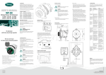
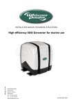
WARNING: Shock Hazard. Keep away from children!
• Avoid moisture. Never expose unit to snow, water etc.
• Unit provides 230VAC,treat the output socket the
same as regular wall AC sockets at home.
WARNING: Explosion hazard!
• DO NOT use the WhisperPower sinewave inverter in
the vicinity of flammable fumes or gases (such as
propane tanks or large engines).
• AVOID covering the ventilation openings.
Always operate unit in an open area.
• Prolonged exposure to high heat or freezing
temperatures will decrease the working life of the unit.
For safe and optimal performance, the sinewave inverter must be used
properly. Carefully read and follow all instructions and guidelines in this
manual and give special attention to the CAUTION and WARNING statements.
PLEASE KEEP THIS MANUAL FOR FUTURE REFERENCE
USER MANUAL
WP-Sine
‘AC Power from the battery’
Disclaimer
While every precaution has been taken to ensure the accuracy of the
contents of this guide, WhisperPower assumes no responsibility for errors
or omissions. Note as well that specifications and product functionality may
change without notice.
Important
Please be sure to read and save the entire manual before using your
WhisperPower sinewave inverter. Misuse may result in damage to the unit
and/or cause harm or serious injury. Read manual in its entirety before
using the unit and save manual for future reference.
Table of Contents
1.INTRODUCTION 2.INSTALLATION
3.UNIT OPERATION
4. TROUBLESHOOTING
5. WARRANTY
6. SPECIFICATIONS
7. CE manufacturer declaration
1. INTRODUCTION
Thank you for purchasing the WhisperPower sinewave inverter. With our
easy to use design, this product will offer you reliable service for providing
AC power and 5V USB power for your home, cabin, RV or Trailer. The WhisperPower sinewave inverter can run many AC-powered appliances when you
need AC power anywhere. The 5V USB power can charge many USB powered
devices. This manual will explain how to use this unit safely and effectively.
Please read and follow these instructions and precautions carefully.
Recreational vehicles • Caravans
Pleasure craft • Holiday homes
High frequency sine wave inverter
IMPORTANT SAFETY INFORMATION
This section contains important safety information for the WhisperPower sinewave inverter. Each time, before using the WhisperPower sinewave inverter,
READ ALL instructions and cautionary markings on or provided with the
inverter, and all appropriate sections of this guide. The WhisperPower sinewave
inverter contains no user-serviceable parts. See Warranty section for how to
handle product issues.
WARNING: FIRE AND/OR CHEMICAL BURN HAZARD
· Do not cover or obstruct any air vent openings and/or
install in a zero-clearance compartment.
WARNING: FAILURE TO FOLLOW THESE INSTRUCTIONS
CAN RESULT IN DEATH OR SERIOUS INJURY
• When working with electrical equipment or lead acid batteries, have someone nearby in case of an emergency.
• Study and follow all the battery manufacturer’s specific precautions
when installing, using and servicing the battery connected to the inverter.
• Wear eye protection and gloves.
• Avoid touching your eyes while using this unit.
• Keep fresh water on hand in the event battery acid comes in contact
with eyes. Ift his occurs, cleanse right away with extensive water for a
minimum of 15 minutes and seek medical attention.
• Batteries produce explosive gases. DO NOT smoke or have an open
spark or fire near the system.
• Keep unit away from moist or damp areas.
• Avoid dropping any metal tool or object on the battery. Doing so could create a spark or short circuit which goes through the battery or
another electrical tool that may create an explosion.
FCC INFORMATION
This equipment has been tested and found to comply with the limits for a
Class B digital device, pursuant to part 15 of the FCC Rules. These limits
are designed to provide reasonable protection against harmful interference
in a residential installation. This equipment generate, uses and can radiate
radio frequency energy and, if not installed and used in accordance with
the instructions, may cause harmful interference to radio communications.
However, there is no guarantee that interference will not occur in a particular installation. If this equipment does cause harmful interference to radio or
television reception, which can be determined by turning the equipment off
and on, the user is encouraged to try to correct the interference by one or
more of the following measures:
• Reorient or relocate the receiving antenna.
• Increase the separation between the equipment and the receiver.
• Connect the equipment into an outlet on a circuit different from that to
which the receiver is connected.
• Consult the dealer or an experienced radio/TV technician for help.
LIMITATIONS ON USE
Do not use in connection with life support systems or other
medical equipment or devices.
2. INSTALLATION
WARNING: WhisperPower recommends that all wiring
be done by a certified technician or electrician to ensure
adherence to the applicable electrical safety wiring
regulations and installation codes. Failure to follow these
instructions can damage the unit and could also result in
personal injury or loss of life.
CAUTION: Before beginning your WhisperPower sinewave inverter
Installation, please consider the following:
• The WhisperPower sinewave inverter should be used or stored in an
indoor area away from direct sunlight, heat, moisture or conductive
contaminants.
• When placing the unit, allow a minimum of 7.5 cm space around
the unit for optimal ventilation.
Material Prepare for Installation
Typical Wiring block diagram of the sinewave inverter:
WP-Sine
12/400
12/1000
12/2000
Marco graag aanleveren
12V Battery Bank
• The use of deep cycle battery is highly recommended for sinewave
inverter application
• For battery size, you need to identify how much you will be using them
between charges. WhisperPower recommends you purchase as much battery
capacity as possible. See more on Battery Run time and Load in Section 3.
Fuse or Circuit Breaker
• DC-rated fuse or DC-rated circuit breaker connected along
the DC positive line is required.
• Select a fase or circuit breaker with a minimum of:
- 63ADC (WP-Sine 12/400)
- 150ADC (WP-Sine 12/1000)
- 300ADC (WP-Sine 12/2000)
• Based on the size of the battery bank chosen on the 12V Battery Bank
above, determine the overall short circuit current rating of the battery
bank from the battery manufacturer. The fuse or circuit breaker chosen
has to be able to withstand the short circuit current that may be
generated by the battery bank.
Disconnect Switch
• Select a Disconnect Switch with the same or higher the rating of the
selected fuse or circuit breaker from the above.
• The Disconnect Switch is used to disconnect the DC power between the
sinewave inverter and the battery bank during service, maintenance or
trouble shooting.
DC Input and Grounding Cable
• Use of low resistance wire is required for all the DC connections between
the inverter and the battery bank.
• Use wiring with maximum cable length of 1.5 meter
and minimal cross-sectional area of:
- 10mm2 (WP-Sine 12/400)
- 25mm2 (WP-Sine 12/1000)
- 50mm2 (WP-Sine 12/2000)
• Important: The unit is grounded through the ground stud of the unit
located near the DC Input
• For the grounding cable connected between the sinewave inverter
chassis to the earth ground, use a matching cable size as used on the
DC Input Cable section.
Reduce load and check if any
ventilation of the unit is blocked
AC Load on sinewave inverter
Although the sinewave inverter can provide high surge power up to two
times the rated output power, some appliances may still trigger on the
inverter protection system. A higher sinewave inverter is required for those
appliances.
Estimate Run time on Load
Following run time are estimates, based on usage of a 12V-120Ah battery
bank for reference. Actual run times may vary.
Load
Cordless Phone
Clock/Radio
Table Lamp
Freezer (250 ltr.)
20” LCD TV
Refrigerator (500 ltr.)
Sump Pump (1/2 hp)
Microwave (mid-size)
Coffee Maker
Consumption
5W
8W
40W/60W
80W
100W
120W
350W
1000W
1200W
Estimate Run time
180 hrs
135 hrs
27 hrs/ 18 hrs
15 hrs
11.5 hrs
9 hrs
3 hrs
49 min
37 min
262
87
87
161
175
175
87
Schuko version
175
175
175
UK version
216
Article nr.
AC output
Power (Continuous)
Power (Peak, 500 mSec)
Output voltage
Output frequency
Total harmonic distortion (THD)
DC input
Nominal battery voltage
Operation range
Input current
No load consumption
DC output
5V USB - Phone Charge
DISPLAY
LED indicator
Digital display
protections
Input Undervoltage Warning
Input Undervoltage Shutdown
Input Undervoltage Recovery
Input Overvoltage Shutdown
Output Power Warning
Output Power Shutdown
Output Short Circuit
Temperature Warning
Temperature Shutdown
Conformity
Operating temperature range
Relative humidity in operation
Ventilation
Dimension (lxdxh)
Weight
Battery connection
Ground Lug Connection
AC output
Warranty
WP-Sine
12/400
61120510
WP-Sine
12/1000
61121500
WP-Sine
12/2000
61122500
400W
800W
230V
50Hz
1000W
2000W
230V*
50Hz*
2000W
1000W
4000W
2000W
230V
230V
50Hz
50Hz
<5% true sine wave
40A
0.4A typical
94A
0.8A typical
12V
10.5 .. 15.5V
187A
1.6A typical
WP-Sine
12/1000 UK
61121501
94A
0.8A typical
WP-Sine
12/2000 UK
61122501
2000W
4000W
230V
50Hz
112
6. SPECIFICATIONS
NOTE: Specifications are subject to change without notice.
112
Corrective Action
Recharge battery immediately
and restart unit
Check battery voltage or if any external
charger is connected to the battery bank
Check load connected to the output.
Reduce load and restart the unit
Turn unit off and wait for 15 minutes
before restarting. Check if any object
has blocked the air flow of the unit
Recharge battery as unit will
shutdown shortly
Reduce load
Schuko version
230
Schuko version
187A
1.6A typical
750mA
No
11.2V
10.5V
11.8V
15.5V
Yes
Yes
Yes
Yes
Yes
Yes
Yes
Yes
Input Voltage / Current, Output Power
Yes
11.2V
11.2V
11.2V
11.2V
10.5V
10.5V
10.5V
10.5V
11.8V
11.8V
11.8V
11.8V
15.5V
15.5V
15.5V
15.5V
Yes
Yes
Yes
Yes
Yes
Yes
Yes
Yes
Yes
Yes
Yes
Yes
Yes
Yes
Yes
Yes
Yes
Yes
Yes
Yes
Directive EMC 2004/108/EC Low voltage directive 2006/95/EC
-20 .. 55°C (derating above 40°C)
95% without condensation
Forced cooling
175x220x82mm 175x323x87mm 230x416x112mm 175x323x87mm 230x416x112mm
1.7kg
2.9kg
5.5kg
2.9kg
5.5kg
M6 studs
M6 studs
M8 studs
M6 studs
M8 studs
M6 studs
M6 studs
M6 studs
M6 studs
M6 studs
2 x UK sockets
1 x Schuko socket 1 x Schuko socket 2 x Schuko sockets 1 x UK socket
2 years
230
230
230
UK version
WhisperPower BV
Kelvinlaan 82, 9207 JB Drachten, The Netherlands
Tel: +31 (0) 512 571 550, Fax: +31 (0) 512 571 599
[email protected], www.whisperpower.com
20141215 WP-Sine 12V manual EN
Remote Switch (Optional for 1000 & 2000W) Connection:
• Insert the Remote Switch to the RJ11 Remote Port located at the Front
AC panel of the sinewave inverter. Please note polarity.
Test the sinewave inverter connection:
• Turn unit on by pressing and holding the On/Off button on the main unit
for about a second until a beep sound occur. The ‘Status’ light turns on
indicating the WhisperPower sinewave inverter is ON. Check the digital
display show measured battery voltage and output power alternatively.
Both AC output and 5V USB are now available.
• Plug in a small AC load like a 40W table lamp or small appliance to the
AC socket to verify AC is available.
• The unit is successfully installed and functioning properly.
Code Condition
E01 Unit has sensed input under voltage and has shutdown
E02 Unit has sensed input over voltage and has shutdown
E03 Unit output has sensed overload or short circuit and was shutdown
E04 Unit has sensed internal temperature was high and has shutdown
E05 Unit has sensed input voltage is low and warning occurs
E06 Unit has sensed load connected is close to overload shutdown limit
E07 Unit has sensed internal temperature is high and is close
to thermal shutdown limit
175
112
• Connect one end of the negative DC input cable to the sinewave inverter
DC negative terminal. Connect the other end of the negative DC input
cable to the battery negative terminal.
• Make sure the Disconnect Switch is in the OFF position.
• Connect one end of the positive DC input cable to the sinewave inverter
DC positive terminal. Connect the other end of the positive DC input
cable to one of the terminal of the Disconnect Switch.
• Connect a DC input cable between the other terminal of the Disconnect
Switch and one side of the terminal of the fuse holder.
• Connect a DC input cable between the other terminal of the fuse holder
and the battery positive terminal.
• Install the selected fuse to the fuse holder.
• Turn Disconnect Switch to ON position.
Understanding the Error Code (Only for 1000 & 2000W)
220
147
352
CAUTION: Reverse the DC Input terminal will damage
the unit and cannot be repaired. Damage caused by reverse polarity connection is not covered by the warranty.
5. WARRANTY
Two Years Limited Warranty
The limited warranty program is the only one that applies to this unit, and
it sets forth all the responsibilities of WhisperPower. There is no other warranty, other than those described herein. Any implied warranty of merchantability of fitness for a particular purpose on this unit is limited in duration to
the duration of this warranty.
This unit is warranted, to the original purchaser only, to be free of defects in
materials and workmanship for two year from the date of purchase without
additional charge. The warranty does not extend to subsequent purchasers
or users. Manufacturer will not be responsible for any amount of damage
in excess of the retail purchase price of the unit under any circumstances.
Incidental and consequential damages are specifically excluded from
coverage under this warranty. This unit is not intended for commercial use.
This warranty does not apply to damage to units from misuse or incorrect
installation/connection. Misuse includes wiring or connecting to improper
polarity power sources.
Limitations:
This warranty does not cover accessories, such as adapters and batteries,
damage or defects result from normal wear and tear (including chips,
scratches, abrasions, discoloration or fading due to usage or exposure to
sunlight), accidents, damage during shipping to our service facility, alterations, unauthorized use or repair, neglect, misuse, abuse, failure to follow
instructions for care and maintenance, fire and flood.
161
323
Sinewave inverter DC Input Connection:
Understanding the Display & Status LED (Only for 1000 & 2000W) Display:
’12.5’ Display shows measured battery voltage
‘0.80’ Display shows total output AC power in kW (800W as shown)
‘E01’ Display shows error or warning code.
See trouble shooting section in details
Status LED:
Green: Unit operation is normal
Amber:Warning is detected. Unit will shutdown at any time.
Please check error code to troubleshoot the unit.
Red: Error is detected and unit has shutdown.
Please check error code to troubleshoot the unit.
ProblemSymptomSolution
The unit is off
Turn unit ON by following the instruction
No output voltage. in Section 4 to turn unit ON
And Status
No
power
to
inverter
Check fuse or the Disconnect switch
LED is off.
(if installed) is either blown or turn OFF
No Output. Status
Check error code Verify the error condition
LED is in Amber
on display
and make correction
(Only for 1000 & 2000W)
7. CE manufacturer declaration
Product: WhisperPower WP-Sine ‘AC Power from the battery’
Whisperpower guarantees that the unit complies
with the relevant standards.
87
Sinewave inverter Chassis Grounding Connection:
DANGER: The sinewave inverter chassis to be grounded properly. Never
operate the sinewave inverter without proper grounding. Failure to do so
will result in death or serious injury.
• Connect the grounding cable’s ring terminal to the unit ground screw.
• Connect the other side of the cable to the common grounding point.
Turn ON and OFF the 230VAC and USB
• Press and hold the “Power/Select” button for 1 second until a
beep is sounded. Display will show the measured battery voltage and
output power alternatively. Status LED will turn green. Both 5V USB
and 230VAC are available.
• Press “Power/Select” button to turn unit off.
Remote ON /OFF (Optional for 1000 & 2000W)
• If optional remote is used, the Remote ON/OFF momentary switch is
connected in parallel with the “Power/Select” button on the unit. Same
procedure applies to ON and OFF the unit.
4. TROUBLESHOOTING
To troubleshoot the unit, please note the error code display on the main unit
and review the “Understanding the Error Codes” in section 3.
416
Sinewave inverter Installation:
• Choose an appropriate mounting location.
• For indoor use, the orientation of the unit can be mounted in any
direction except with the DC Input panel facing downwards.
• For RV installation, the unit has to be mounted flat on horizontal surface.
• Drill the 4 mounting holes, position the mounting screws and place the
inverter in position and fasten the inverter to the mounting surface.
3.UNIT OPERATION
WARNING: RISK OF EQUIPMENT DAMAGE
• Do not connect an AC power source like utility power or
generator to the unit 230VAC outlets.
112
Installing the Sinewave inverter System
WARNING: Electrical Shock Hazard
The unit ‘On/Off’ switch does not disconnect the DC
power from the battery. Use the DC Disconnect Switch or
disconnect the DC input cables connection to disconnect
the DC power from the battery before working on any
circuits connected to the unit. Failure to follow these
instructions can result in death or serious injury.