1
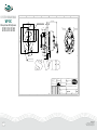
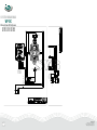
5
4
3
2
Maintenance and repair
Use only original spare parts.
1. INTRODUCTION
Thank you for choosing a professional quality product from
WhiperPower. WP-DC Beltpower is a system designed to be driven
by a belt from a pulley on a vehicle’s or ship’s propulsion engine.
In most cases an additional pulley has to be installed. The alternator’s output is connected to the WP-ACR, which converts and
regulates the incoming alternating current in order to charge a 12
or 24 Volts battery bank using a state-of-the-art charge algorithm.
1
A
WP-DC
WhisperPower DC Beltpower
12/90 12/130 12/160
24/75 24/110 24/150
CAUTION !
When service has to be carried out while the engine
is running, be aware of moving parts !
C
Problem
WARNING !
B
Make sure the WP-DC Beltpower and engine are
sescured against unexpected and unintentional
switching on when switched off for maintenance or
repair.
-Remove the key from the engine ignition switch;
-Disconnect
the batteries or remove the5DC fuse(s);
4
-Be sure that third parties cannot reverse the
measures taken.
This manual is valid for the following products:
Part number
60212091 60212131
60212161 60115100 60224076 60224111 60224151 60115200 Discription
WP-DC Beltpower 12V/90A Alternator
WP-DC Beltpower 12V/130A Alternator
WP-DC Beltpower 12V/160A Alternator
WP-ACR 12V Alternator Charge Regulator
WP-DC Beltpower 24V/75A Alternator
WP-DC Beltpower 24V/110A Alternator
WP-DC Beltpower 24V/150A Alternator
WP-ACR 24V Alternator Charge Regulator
D
C
1
2
3
Electrical connections:
- Check the wiring at least every six months. Burned cables, poor
connections etc. must be corrected
immediately. DC
A3
D
Monitoring and control
Refer to Figure 1: the battery charging performance can be monitored by means of the WP-ACR display.
E
SHEET
IPE
CE PRINC
TOLERAN
15
ISO 80
IFIED:
ISE SPEC
ANGLE
THIRD
OTHERW
:
S
S
N
:
GE
LES
TIO
UN
ARP ED
Material
PROJEC
FER SH
AM
CE
mm
:
CH
AN
UNITS
L TOLER
GENERA 68-m
CES
27
LERAN
TO
E
NEN ISO
AC
AND PL
FORM
22553
1101
NEN EN
NEN-ISO
4
SYMBOL
NEN363
STATUS:
WELDING
DATE
ACC. to
HNESS
TURE
ROUG
SIGNA
3-9-2014
ME
NA
14
-20
-05
19
ING:
J.M.
DRAW
N
838
DRAW
5014A12
M.B.
CHK'D
ARTICLE
91
SHEET 1
OF 1
No output
power, one of
the LEDs is on.
B
[field]
on WPACR is 0V.
:1
SCALE:1
104,08
248,20
248,20
Regulator stays
in bulk mode all
the time.
D
WP-ACR does
not return to
bulkD mode when
a high load is
switched on.
A schematic view of the three-step charging process is presented
in Figure 2.
15
Fuse in red wire is blown.
Two pole (red and blue)
field connector is loose.
Replace the fuse.
Check field connector on
the alternator.
Problem in the wiring.
Check red and blue wires to
the field connector.
E
Figure 2: Three-step battery charging curve
NAME
DRAWN
J.M.
CHK'D
M.B.
TOLERANCE PRINCIPE
ISO 8015
FINISH:
-
STATUS:
Absorption time Wrong setting of the
is too long/short. absorption timer.
A3
WP-ACR is in
Another device is charging
float mode, but the batteries.
battery voltage is
still at absorption
or bulk level.
REVISION
DC Belt Alternator 12-160 VDC
Design
19-5-2014
19-05-2014
F
PRINTED
DRAWING:
B+
B-
ARTICLE NO.
5014A12792
60212161
3-7-2014
+ Pos
Out
1
4
Defective WP-ACR.
The absorption timer
keeps the WP-ACR is in
absorption mode. When in
float mode, the regulator
will stay in this mode.
WP-ACR cannot sense
battery temperature.
TITLE:
DATE
Use a more powerful
alternator. Consult
WhisperPower for advice.
Replace WP-ACR.
Nothing: this is a normal
situation. If necessary
switch off engine and start
again.
SHEET FORMAT:
Material:
SIGNATURE
Capacity of the charging
system is too low.
Weight: 4837.45 gram
- Neg
Out
SCALE:1:3
2
Check wiring between
battery and [on] for
corrosion. The line should
15,10
not be used by other loads.
Check for voltage drop
across oil pressure switch
(if installed).
Wrong setting of the charge Adjust the charge voltage.
voltage.
DO NOT SCALE DRAWING
PROJECTION : THIRD ANGLE
UNITS : mm
Replace WP-ACR.
Switch off a load.
Check batteries and replace
if necessary.
15
W-Contact
UNLESS OTHERWISE SPECIFIED:
CHAMFER SHARP EDGES
GENERAL TOLERANCE
NEN ISO 2768-m
FORM AND PLACE TOLERANCES
NEN-ISO 1101
WELDING SYMBOL NEN EN 22553
ROUGHNESS ACC. to NEN3634
Reconnect blue wire.
Check resistance of
field windings. Replace
alternator.
Reconnect black [gnd] wire.
Alternator is overloaded.
Defective batteries, shortcircuit between cells.
Output voltage is The regulator measures a
too high.
too low battery voltage and
tries to compensate.
169,98
15,10
E
3
Reconnect brown wire.
No output power, Black [gnd] wire is loose.
all LEDs are off.
[reg on] and
[+batt] on WP- WP-ACR defective.
ACRC are 12/24V.
104,08
104,08
The WP-ACR controls the alternator’s output voltage. It monitors
and manages the best charge process available for lead-acid,
gel and AGM batteries. The three automatic charging stages are
shown by their corresponding LEDs: Bulk (yellow), Absorption (yellow) and Float (green).
Temperature-compensated charging
The delivery includes a battery temperature sensor enabling the
WP-ACR to adapt the charge voltages to the battery temperature,
as shown
in Figure 3. This will extend the
life of your batteries.
1
2
Brown [reg on] wire is
loose.
84,63
Figure 1: ACR front display
F
Reconnect black [gnd] wire.
Start the engine.
Replace the fuse.
231,63
C
169,98
Black [gnd] wire is loose.
Engine is not running.
Fuse in brown wire is
blown.
Blue [field] wire is loose.
218,23
Field windings
of the
alternator
are defective.
204,25
C
CAUTION !
Replace
the fuse.
5
Clean connections. Replace
cables if burned.
Faulty oil pressure switch or Replace faulty item.
ignition relay (S1).
84,63
D
No voltages at4 Battery fuse is blown.
all, LEDs are off. Battery connections are
bad.
A
m
2
Always be aware that your actions may have an impact on safety
and/or on product performance. Carefully follow instructions
documented.
Battery acid is corrosive; wear protective eyewear
when handling batteries. If battery acid would come
in contact with eyes, rinse with a lot of water for a
minimum of 15 minutes and seek medical attention.
NO.
602120
Solution
Switch off DC to prevent
field windings from being
damaged by overheating.
Check oil pressure switch/
ignition relay for correct
operation (circuit must be
broken when engine is not
running).
231,63
218,23
204,25
1
2. INSTRUCTIONS FOR USE
Use the WP-DC Beltpower for intended purpose only:
- to charge batteries and to supply loads connected to these batteries, in permanent systems;
- with fuses protecting the wiring between the system components
and the battery;
- in a technically correct condition;
- in a closed, well-ventilated room, protected against rain, moist,
dust and condensation;
- observing the instructions in this manual.
WhisperPower is not liable for any damage caused by using the
WP-DC Beltpower for other purposes and in other ways than
mentioned above.
N
REVISIO
Possible cause
Alternator is
Rotor field windings are
getting hot while excited while they should
engine is not
not.
running.
No output power,
all LEDs are off.
[+batt] on WPACR is 12/24V,
[reg on] is 0V.
.13 gra
t: 4349
Weigh
3
CAUTION !
Risk of equipment damage
or personal injury
lt Altern
8
Technical drawings
Note: additional drawings of all BetlPower types can be obtainedB
from the WhisperPower website.
3-9-2014
PRINTED
-90 V
ator 12
DC Be
Design
B
F
:
FORMAT
TITLE:
4
The lean and mean
on-board power generating system
ING
E DRAW
T SCAL
DO NO
FINISH:
Throughout this manual, the following alert symbol is used to
indicate potential hazard:
1
A
A
Safety guidelines and measures
This manual serves as a guideline for safe and effective installation and use of the WP-DC Beltpower. It should be kept in a dry
and clean place, and be available any time.
Please read this manual carefully before installing and using your
WP-DC Beltpower.
DC alternator
with three-step charge regulator
Alternator mounting, belt tension and condition:
- Check the mounting of the alternator as well as belt tension
and condition after the first 50 running hours, then every 150
running hours or at least every year, whichever comes first.
- Check if the alternator is securely mounted to its brackets and
that the brackets are bolted securely to the engine.
2 inspect
- Before
adjusting belt tension,
the belt for glazing, 3
6
7
cracks, or dryness. If the belt is in satisfactory condition, check
its tension with a belt tension gauge. Loose belts will slip on the
pulley, fail to turn the alternator’s rotor and finally overheat the
alternator. Adjust if necessary, following the instructions given in
the Installation section.
- A worn or damaged belt should be replaced. After installing a
new belt, run the engine with full load connected to the alternator for approximately 15 minutes. Then check the belt tension
again and adjust it if necessary.
104,08
USER’S MANUAL
3. TROUBLESHOOTING
In case of any fault, it is recommended to consult the ‘Maintenance and repair’ section before checking the table below.
If necessary, contact your local WhisperPower Service Centre.
See www.whisperpower.com.
Alternator condition:
- Check the alternator at least every six months. Alternator
surfaces should not show any buildup of dirt, grease or dust.
Air flow passages must also be clear so that air can easily pass
through the unit. The alternator’s bearings are greased for life
and do not require maintenance
B
Connect battery
TOLERANCE PRINCI
UNLESS OTHERWISE
SPECIFIED:
temperature
sensor
or
ISO 8015
CHAMFER SHARP EDGES
attach
to
batteries.
GENERAL TOLERANCE
PROJECTION : THIRD
NEN ISO 2768-m
Adjust
the absorption timer. UNITS : mm
FORM AND PLACE TOLERANCES
NEN-ISO 1101
WELDING SYMBOL NEN EN 22553
ROUGHNESS ACC. to NEN3634
Switch off all other charging
devices and NAME
check the SIGNATURE
battery
again.
DRAWN voltage
J.M.
CHK'D
19-05-201
M.B.
PRINTED
3-7-2014
SHEET 1 OF 1
3
4
WARNING !
Never keep the WP-DC Beltpower acitve when the
engine is off. Otherwise, alternator windings will
become overheated.
W (Brown)
Gnd (Black)
Reg+ (Green)
B+ (Red)
DF (Blue)
Fuse 10 A
W
Figure 3: Battery temperature compensation curve
Reg+
+
WhisperPower BV
Kelvinlaan 82, 9207 JB Drachten, Netherlands
Tel: +31 (0) 512 571 550, Fax: +31 (0) 512 571 599
[email protected], www.whisperpower.com
20140826 5014 DC BeltPower Manual
-
Disclaimer
WhisperPower can accept no responsibility for possible errors or
omissions in catalogues, brochures and other printed material.
WhisperPower reserves the right to alter its products without
notice.
This guide must be followed carefully. WhisperPower can accept
no responsibility for errors related to incorrect or unsafe installation and/or handling.
10 A
Fuse
B+
F+
GND
Ignition or oil
pressure switch
DF (Dynamofield)
2
Little instruction is needed to operate the WP-DC and WP-ACR.
Once installed as described in Section 4, the alternator will funtion
with minimal user interaction.
2
Never use the WP-DC Beltpower in locations where
there is a risk of explosion due to gases, potentially
flammable products or dust.
Reg +
1
WARNING !
1
- High charge current at low rpm of the alternator
- Recharging the battery for the full 100%
within a short period
- Three-step charge algorithm,
suitable for GEL, AGM and ‘wet’ batteries
- Extends battery life considerably
- Temperature sensor included
- Waterproof IP 65 enclosure
DATE
19-5-2014
2. Align the alternator pulley with the engine drive pulley as
shown below and tighten the bracket mounting bolts.
Unpacking
The delivery typically includes:
- WP-DC Beltpower Alternator
- WP-ACR Alternator Charge Regulator,
including cable harness and temperature sensor
- This user’s manual
- Installation drawings
You will also need an engine-specific mounting bracket for the
alternator, a belt tensioner (in case of a multi-groove belt) and
associated belt(s).
You will also need an engine-specific mounting bracket for the
alternator and associated belt(s).
Check all items for possible (transport) damage. Do not use the
product when damaged. If in doubt, contact your supplier.
Check whether the nominal DC voltage is consistent for all applied
components (e.g. a 12V alternator with a 12V WP-ACR and a 12V
battery set).
Mounting the alternator (multi-groove belt)
1. Attach the alternator and its mounting bracket to the engine
using flat washers, lock washers and bolts.
2. Similarly, mount the belt tensioner referring to the applicable
instructions, if available.
3. Depending on the type of belt tensioner, push, pull or turn it
out of the way and install the belt. Then carefully release the
tensioner.
4. Check if the pulleys are properly aligned and correct if necessary. Check if the belt is tensioned such that it does not slip on
the alternator fan pulley when you try to rotate the pulley by
hand.
5. Check that all mounting bolts have been tightened using
adequate torque (see table below).
3. Loosely attach the alternator adjustment strap (D above) to
the alternator adjustment ear (C) with the bolt, flat washer and
lock washer.
4. Tighten the belt by applying pressure to the alternator front
housing (the rear housing not being solid enough) and tighten
the bolt to the adjustment ear (C). Set the belt tension in
accordance with the manufacturer’s specifications or, alternatively, such that the belt on alternator fan pulley will not slip
when you try to rotate the alternator by hand.
5. Taking into account the ‘Standard torque chart’, tighten all
remaining alternator mounting bolts and retighten all other
bolts to secure the installation.
Mounting the WP-ACR
Install the WP-ACR not too far from the alternator, taking into
acount the length of the cable harness (1.5m).
Wiring instructions
Connect all items as shown in the installation drawings (refer to
front page; additional drawings can be obtained from the WhisperPower website). All wiring is combined in the cable harness.
Apply battery cables as specified in the table below.
CAUTION !
Failure to de-energize the [reg on] terminal will
damage the alternator’s field windings.
If any of the above tests is unsuccessful, remove the DC fuses
and double-check the wiring. Refer to the Troubleshooting
section.
6. Check whether all bolts are securely mounted. Also check belt
alignment and tension.
Initial adjustment of the WP-ACR
The WP-ACR has three trimmer potentiometers for adjusting the
absorption voltage, float voltage and absorption time. These must
be set using a 0.4×2.5mm flat blade screwdriver.
CAUTION !
Invalid and especially too high settings can cause
serious damage to your batteries or to sensitive
equipment connected to these.
CAUTION !
Recommended wire sizes and fuses:
Mounting the alternator (V-belt)
1. Loosely attach the mounting bracket to the engine with the
engine mounting bolts. Position the alternator mounting foot (A
and B in the figure below) between the two ears on the mounting bracket using the alternator mounting bolts. The ear at
the rear side of the alternator housing should be able to move
freely in the direction of the arrow (A in the figure) in order to
avoid mechanical stress.
Commisioning checks
Before starting the engine follow all steps described below:
1. Check all wiring, then place the DC fuse(s) to connect the batteries to the alternator and to the WP-ACR.
2. Check whether all LEDs on the WP-ACR are off.
3. Energize the ‘ON’ terminal by either turning on the ignition
switch (DO NOT START the engine) or by putting a jumper
across switch S1 (also see Figure 4). Check whether the three
LEDs start to blink. After some 10 seconds the yellow bulk LED
will illuminate.
4. Check whether the alternator field is energized by touching the
shaft of the alternator with a screwdriver. It should be strongly
magnetic.
5. De-energize the [reg on] terminal by turning off the ignition
switch or by removing the jumper. All LEDs should go off and
the field should no longer be magnetic.
ModelWire ≤ 3m
Wire > 3mFuse
12V / 90A
35mm250mm2125A
12V / 130A
50mm270mm2160A
12V / 160A
50mm270mm2200A
24V / 75A
25mm235mm2100A
24V / 110A
35mm250mm2160A
24V / 150A
50mm270mm2200A
Special attention is drawn to the brown and red wires in the cable
harness:
- Refer to Figure 4: the green wire (‘Reg+’ / ‘ON’) must be connected to the engine ignition relay or, preferably, an ungrounded
oil pressure switch.
- The red wire (‘B+’ / ‘+Batt’) can be connected to the
positive (+) pole of the battery or to the B+ terminal of the
alternator.
However, if the DC Beltpower is meant to charge multiple
batteries together with a WP-WBI Battery isolator, the red wire
must always be connected to a positive (+) battery pole. Do not
install the DC fuse in the positive cable until the installation is
completed.
Do not attempt to drive the potentiometers past their
limits. You might damage them.
Absorption voltage:
- Turn the potentiometer counterclockwise until its stop, then
rotate it 90° clockwise (approx. 14.25V/28.5V).
Float voltage:
- Turn the potentiometer counterclockwise until its stop, then
rotate it 90° clockwise (approx. 13.25V/26.6V).
Absorption time:
- Turn the potentiometer clockwise until its stop, then rotate it
45° counterclockwise (approx. 4 hours).
The above settings may be adequate for some installations.
However, it is strongly recommended to check the actual charge
voltages in the absorption and float modes and to follow the
detailed instructions for fine adjustment below.
In-operation testing and adjustment
For these tests, you will need to measure the voltage on the battery terminals in order to get the most accurate reading. Using the
three potentiometers, you can adjust the charging system to the
demands of the electrical installation.
CAUTION !
When the engine is running, be aware of moving
parts like belts.
CAUTION !
Invalid settings of the potentiometers can cause
serious damage to your batteries.
Refer to the battery manufacturer´s specifications or use the
generic settings mentioned below. Keep a record of setting
changes.
Follow all steps described below:
1. Be sure no loads or any other charging sources are on. The
battery should be fully charged. Disconnect the battery temperature sensor. Measure and record the battery voltage.
2. Start the engine.
3. Check for abnormal noise or vibration.
4. The yellow [bulk] LED on the WP-ACR will illuminate, indicating
that the charge cycle begins.
5. Measure the battery voltage. It should be higher than at step1.
The battery voltage rises until the yellow [abs] LED illuminates.
6. The WP-ACR is now in absorption mode. When measured at
25°C / 77°F, battery voltage should stabilize at 14.25 ± 0.05V
for a 12V alternator or 28.50 ± 0.10V for a 24V alternator.
7. Before adjusting the absorption voltage, increase the engine
rpm slightly to verify that the charge voltage does not increase.
If it does, either wait for the battery to become fully charged
or find a high enough rpm where the voltage does not change
with increasing rpm.
Rotate the [abs] potentiometer carefully to set the absorption
voltage at the desired value. With good wiring and good voltage sensing, the resolution should be within 0.03 Volt.Respect
the limit specified by the battery manufacturer.
8. The absorption stage may take quite a while. For step 9 you
might want to reduce the absorption time temporarily to 2 min
by turning the [time] potentiometer counterclockwise until its
stop.
9. When the absorption time has elapsed, the green [float] LED
will illuminate. The WP-ACR is now in float mode. Wait for
about 10 minutes to allow the battery voltage to settle. When
measured at 25°C / 77°F, the battery voltage should stabilize
at 13.25 ± 0.05V for a 12V alternator or 26.50 ± 0.10V for a
24V alternator.
10.If the float voltage needs to be adjusted, rotate the [float]
potentiometer. When setting the float voltage near its lower
limit, you may have to switch on some DC loads to trigger the
alternator because it takes some time for the voltage to settle
from the higher absorption voltage.
11.Stop the engine and reconnect the battery temperature sensor.
Check belt alignment and tension, and adjust if necessary.
12.Finally, set the absorption timer. Adjustable range: 2 minutes
up to 4.5 hours. The basic 4 hour setting is appropriate for
most systems. Exceptions might be:
- Extension of the absorption time to do some intentional
overcharging to regain lost capacity.
- Shorten the time if you stop and start the engine often each
day.
If all of the above steps were successfully completed, the WP-DC
Beltpower system is ready for operation. If not, check the Troubleshooting section.
5. SPECIFICATIONS
12v alternator
WP-ACR Charge regulator
Model
12V/90A
12V/130A
12V/160A
Model
12VDC
24VDC
Art. no.
60212090
60212130
60212160
Art.no.
60115100
60115200
12VDC
24VDC
GENERAL
GENERAL
Power
(continuous)
1080W
1560W
1920W
Max. current
(continuous)
90A
130A
160A
Voltage
Nominal voltage
Temperature sensor
Cable harness
Yes, length 1.5m
Connection plug
regulator / alternator
12VDC
Yes, cable length 6m
WhisperPower alternator
mechanical
Alternator type
Dimensions
(h × w × d)
195 × 205 × 140mm
250 × 225 × 175mm
ELEctrical
Net weight
5.5kg
10.1kg
Charge voltage
- Absorption
14.25VDC
28.50VDC
Mounting style
Spool 86
J180
Bi-directional
Yes
Charge voltage
- Float
13.25VDC
26.50VDC
Absorption voltage range
13 ..15VDC
27 .. 31VDC
13 .. 13.9VDC
26 .. 27.8VDC
Yes
Yes
ACCESSORIES / additional materials
WP-WBI 150-2IG
Battery isolator
Choose alternative
battery isolator
60115002
Standard pulley
60212001
60212006
Optional pulley
60212002
60212005
24V alternator
Model
24V/75A
24V/110A
24V/150A
Art. no.
60224075
60224110
60224150
Float voltage range
Absorption time
0 .. 4.5h
Temperature
compensation
-30mV/°C
-60mV/°C
Rev counter input
Prepared
Operating
temperature range
-20 .. 80°C
settings / read out
GENERAL
Power
(continuous)
1800W
2640W
3600W
Max. current
(continuous)
75A
110A
150A
Voltage
24VDC
Voltage settings
By trimmers on device
Time settings
By trimmers on device
Status read-out
LEDs
Communication bus
Dimensions (h × w × d)
Dimensions
(h × w × d)
250 × 225 × 175mm
250 × 250 × 185mm
Net weight
10.1kg
13.1kg
J180
Spool 213
Mounting style
Yes
Yes
60115002
Standard pulley
60212006
Optional pulley
60212005
Weight
117 × 120 × 27mm
0.4kg
Packaging size (h × w × d)
Protection degree
330 × 230 × 65mm
IP65
Yes
ACCESSORIES / additional materials
WP-WBI 150-2IG
Battery isolator
WhisperConnect prepared
mechanical
mechanical
Bi-directional
WhisperPower, low voltage, brush type
6. WARRANTY TERMS AND CONDITIONS
WhisperPower guarantees that the equipment has been produced
in accordance with the legally applicable standards and specifications. WhisperPower assures the product warranty of the WhisperPower DC Beltpower during two years after purchase, on the
condition that all instructions and warnings given in this manual
are taken into account during installation and operation.
The warranty is limited to the costs of repair and/or replacement
of the product by WhisperPower only. Costs for installation labor or
shipping of the defective parts are not covered by this warranty.
7. CE MANUFACTURER’S DECLARATION
Issuer’s name:
WhisperPower BV
Issuer’s address:
Kelvinlaan 82, NL-9207 JB Drachten
Object of the declaration:
WhisperPower alternators and regulators,
Article nos. 60212091, 60212131, 60212161, 60115100,
60224076, 60224111, 60224151 and 60115200.
The object of the declaration described above is in conformity with
the requirements of the following Directives and standards, as applicable:
2004/108/EC (EMC Directive)
EN61000-6-3:2007 (Electromagnetic compatibility [EMC]. Generic
standards. Emission standard for residential, commercial and lightindustrial environments )
EN61000-6-1:2007 (Electromagnetic compatibility [EMC]. Generic
standards. Immunity for residential, commercial and light-industrial
environments )
2006/95/EC (Low Voltage Directive)
EN60950:2000 (Safety of information technology equipment)
Signed for and on behalf of:
WhisperPower BV
M. Favot
Chief Technical Officer
Drachten, October 7, 2014
Figure 4: S1 switch connections
WhisperPower BV
Kelvinlaan 82, 9207 JB Drachten, Netherlands
Tel: +31 (0) 512 571 550, Fax: +31 (0) 512 571 599
[email protected], www.whisperpower.com
20141215 DC BeltPower Manual EN
4. INSTALLATION
During installation and commissioning of the WP-DC Beltpower system, the Safety Guidelines & Measures are applicable at all times.
1
SYSTEM DRAWINGS
4
3
A
WhisperPower DC Beltpower
12/90 12/130 12/160
24/75 24/110 24/150
7
8
A
135,9 ±1,50
bidirectional rotation
138.5 Max.
6
5
27,2 ±0,15
13
B+
M6x1.0 THD
BM5x8 THD
37,1
17,3
B
165,6
190.3 Max.
84
B
73.4 Nominal
36°
C
C
10,3
30°
20,1
11,2
25,4
WP-DC
2
8.7 Thru Holes (3)
D
D
E
UNLESS OTHERWISE SPECIFIED:
CHAMFER SHARP EDGES
GENERAL TOLERANCE
NEN ISO 2768-m
FORM AND PLACE TOLERANCES
NEN-ISO 1101
WELDING SYMBOL NEN EN 22553
ROUGHNESS ACC. to NEN3634
NAME
TOLERANCE PRINCIPE
ISO 8015
FINISH:
-
PROJECTION : THIRD ANGLE
UNITS : mm
SIGNATURE
SHEET FORMAT:
DATE
J.M.
19-5-2014
CHK'D
M.B.
19-05-2014
STATUS:
Design
DRAWING:
F
5014A12838
3-7-2014
Weight: 4349.13 gram
1
2
3
A3
Material:
TITLE:
DRAWN
PRINTED
DO NOT SCALE DRAWING
DC Belt Alternator 12-90 VDC
ARTICLE NO.
REVISION
60212091
SCALE:1:2
SHEET 1 OF 1
4
WhisperPower BV
Kelvinlaan 82, 9207 JB Drachten, Netherlands
Tel: +31 (0) 512 571 550, Fax: +31 (0) 512 571 599
[email protected], www.whisperpower.com
SYSTEM DRAWINGS
WP-DC
WhisperPower DC Beltpower
12/90 12/130 12/160
24/75 24/110 24/150
B- Neg
Out
Reg +
+ Pos
Out
Ignition or oil
pressure switch
DF (Dynamofield)
B+
- Neg
Out
W-Contact
B-
W-Contact
2
+ Pos
Out
2
10 A
Fuse
B+
Fuse 10 A
1
+
Starter
Battery
Fuse
-
1
2
2
Service
Battery
+
B+
F+
GND
W
WBI
WBI 150-2 IG
10 A
Ignition or oil
pressure switch
2
1
Fuse
B+
F+
GND
1
Fuse 10 A
Reg+
W (Brown)
Gnd (Black)
Reg+ (Green)
B+ (Red)
DF (Blue)
W
-
DF (Dynamofield)
Reg+
W (Brown)
Gnd (Black)
Reg+ (Green)
B+ (Red)
DF (Blue)
1
Reg +
+
WhisperPower BV
Kelvinlaan 82, 9207 JB Drachten, Netherlands
Tel: +31 (0) 512 571 550, Fax: +31 (0) 512 571 599
[email protected], www.whisperpower.com