1
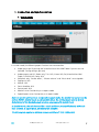
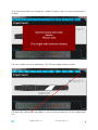
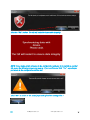
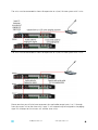
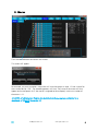
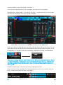
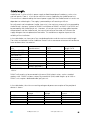
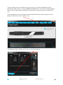
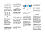
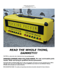
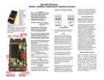
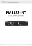
AUDIOCONTROL12.8
GRAPHICAL INSTALLER
INTERFACE
Online user manual
1
Manual content:
Page
Getting started
------------------------------------------------3
RS232 communication
------------------------------------------------5
Graphic installer interface:
1. Connection and synchronization
a. Installer mode
b. Expert mode
2. Settings
3. Global config
4. Audio inputs
5. Audio outputs
6. Wall panel
7. Paging mic
8. Macros
9. Event scheduler
10. Feature pack*
a. Message player*
b. Logic inputs*
c. Logic outputs*
d. Zone combining*
11. Monitor
12. Export / Import
------------------------------------------------7
------------------------------------------------8
------------------------------------------------13
------------------------------------------------18
------------------------------------------------24
------------------------------------------------28
------------------------------------------------34
------------------------------------------------36
------------------------------------------------41
------------------------------------------------50
------------------------------------------------55
------------------------------------------------56
------------------------------------------------64
------------------------------------------------68
------------------------------------------------69
------------------------------------------------77
------------------------------------------------79
Factory default settings
------------------------------------------------81
Specifications
------------------------------------------------85
Cable length
------------------------------------------------88
Instruction set AudioControl 12.8
------------------------------------------------90
*Feature pack required (AC12.8FP)
DISCLAIMER: the screenshots, items and function descriptions mentioned in this manual are
subject to change. Apart-Audio reserves the right to make changes without prior notice.
[email protected]
www.apart-audio.com
2
AUDIOCONTROL 12.8 GRAPHIC INSTALLER INTERFACE
Getting started:
Connecting the AudioControl unit to the computer via RS232:
All you need is a serial cable (straight, no null modem cable !!!) and a working serial port on
your computer. Alternatively, an industry standard USB to RS232 converter will do the job.
IMPORTANT: Consult the manual of your USB to serial converter and make sure the drivers for
the converter or integrated serial port are successfully installed before starting the AudioControl
graphical installer interface program. Check the Windows device manager on your computer
and make sure there are no unknown or disabled communication devices in the list (usually
these communication devices are listed under “Ports (COM & LPT)”).
The program will automatically scan all available com ports on your computer and will
automatically configure the serial port the AudioControl unit is connected to. No further user
action is required for making the connection. No specific drivers are needed for the
AudioControl unit, because all communication with the computer is done via RS232 commands.
Please note: depending on your hardware configuration, not all com ports listed in the Windows
device manager are RS232 ports ! Consult an IT professional in case of doubt or check the com
port properties in device manager. RS232 communication with Audiocontrol is bi-directional (Tx
& Rx).
Despite the fact that serial ports are becoming rare on modern computers, they are still
commonly used in home/office automation and control systems. There are many benefits to
using serial ports: the protocol is very reliable and does not depend on operating system driver
policies or restrictions.
For your reference, default serial port parameters are as follows: baudrate 19200, 8 databits, 1
stopbit, no parity. The serial cable used for communicating with AudioControl is a straight
through, one on one serial cable (NO null modem cable). If you experience any communication
problems, first check the RS232 A in/out leds on the front panel. These should flash (briefly)
when commands are sent/ received successfully. When the leds remain unlit at all times, no
connection has been made and you will be unable to configure the unit. Check the RS232
troubleshooting guide on page 4 or consult an IT professional.
Note: connection from the PC to the AudioControl unit is made with a standard RS232
straight cable, by default connected to the front RS232/A port on the AudioControl unit.
During the boot sequence (power up), the programming RS232 port status led will light up
a few seconds.
[email protected]
www.apart-audio.com
3
Straight RS232 cable: PC to AudioControl port A:
The RS232/B and C connectors are meant for communication between the AudioControl unit
and other peripherals. If you want to control Apart-audio RS232 compatible devices, you need a
CROSSED serial cable. For other brands, a STRAIGHT or CROSSED serial cable is used, depending
on the peripheral device.
Crossed cable: AudioControl to Apart-audio peripherals:
Keep your software and firmware up to date! Check our website for the latest firmware and
graphic installer interface program:
www.apart-audio.com
Before installing the latest interface program, please uninstall the previous version via the
Windows control panel / programs & features / uninstall. Uninstalling the program will not erase
your expert password stored on your computer.
[email protected]
www.apart-audio.com
4
RS232 COMMUNICATION:
In case you want to identify the RS232 port needed for communicating with the GII software:
power off the AudioControl unit and power it on again. During the boot sequence (power up),
the RS232 port led necessary for programming the device will light up for a few seconds.
Default RS232 port is the front port (A). Connect the serial cable to the A port.
When the connection via RS232 fails, check your serial cable: is it straight or crossed ? If you
don’t know, measure the pins 1 on 1 with an ohmmeter: pin 2 is connected to pin 2, pin 3 to 3,
5 to 5. Now check the RS232 communication port or communication adapter driver on the PC
and make sure the RS232 communication port/adapter on your computer is compatible and fully
functional in both directions (Tx AND Rx). When the heartbeat leds on the front of the unit don’t
light up, there is no communication possible between the computer and the unit. When the
computer sends a command, the RS232 IN led on the AudioControl unit will blink. At the same
time the unit will confirm by sending a reply to the computer: the RS232 OUT led will blink.
A good way to troubleshoot communication problems is to install a third party terminal
communication program, such as our preferred “Hercules” communication program, available
for download free of charge. Download and install the program:
http://www.hw-group.com/products/hercules/index_en.html
Click the “Serial” tab, select the COM port and adjust the com port settings by changing the
baudrate to 19200. Click the “Open” button. Now connect the AudioControl’s RS232 port and
power on the unit. When communication is ok, the screen will look like this.
[email protected]
www.apart-audio.com
5
Now enter “get info” followed by “<CR>” in the “Send” field and click “Send”.
get info<CR>
The AudioControl unit will now start to transmit ALL settings to the computer. If this works
flawlessly, the RS232 port should be compatible with the AudioControl program. The screen will
look like this:
Click “Send”
NOTE: depending on your computer’s hardware configuration, operating system or user
account permissions, communication via RS232 may be restricted or even forbidden.
Contact an IT professional in case of doubt.
Do not forget to “close” the COM port after use.
[email protected]
www.apart-audio.com
6
1. Connection and synchronization
a. Installer mode:
In installer mode, the following expert functions are not accessible:
•
•
•
•
•
•
•
•
•
Audio inputs tab: Eq settings are limited to classic Bass-Mid-Treble. Dynamics are not
available. Config settings: gain only
Audio outputs tab: I/O: faders only, Trim: N/A, X-over: N/A, Eq limited to Bass-MidTreble, DYN-LIM: N/A, Delay: N/A
Wallpanel: only “Source select”, “Master volume” and “Music level” are assignable
Paging mic: N/A
Macros: N/A
Event scheduler: N/A
Feature pack: N/A
Monitor: same functionality as in expert mode
Export/Import: same functionality as in expert mode
Note: in case the unit has been configured in expert mode, the installer can not access the
unit via RS232. Installer mode is only available when the unit has been reset to factory
defaults (out of the box behaviour), or when programmed in installer level.
In installer mode, the unit behaves like a classic multizone preamplifier/matrix with basic
tone controls. In expert mode, all features are available.
The GII program requires a minimum screen resolution of 1000 x 600 pixels.
[email protected]
www.apart-audio.com
7
b. Expert mode:
Enter your expert key (10 characters, case sensitive !)
Click remember to store the expert key on your computer, then click “Connect to device”. A
non-expert user can still import a file generated by an expert by clicking the “Import” button.
[email protected]
www.apart-audio.com
8
Click the “Import” button, a computer browse window will pop up. Search for the file you want
to import, select it and click “Open” in the computer browse window to import it. Messages
recorded with the feature pack message player (optional) can not be exported/imported !
Note: when you enter a wrong expert code 3 times in a row, you will need to restart the
AudioControl unit by cycling the mains power. An error window will pop up. Click “OK”
to exit, cycle power and retry.
In order to receive an expert level code, please contact your local distributor.
[email protected]
www.apart-audio.com
9
In case the expert password was already successfully stored on your computer, the following
screen will appear when starting the GII program:
Open the installer interface program and click the “Connect to device” button.
The unit will synchronize all settings with the computer.
To monitor the serial communication from the beginning, double click the text “Found a
compatible AudioControl device” to open the RS232 log screen.
NOTE: when you change a value, for example, change the master level fader in zone 1, the
command will show up in the logscreen, “Outgoing” field. This can be handy if you want
to control the AudioControl unit using RS232 commands sent by other devices.
[email protected]
www.apart-audio.com
10
Once the synchronization has started, this window will pop up. Wait until the synchronization is
finished.
The main window has clearly labeled tabs. Click the tabs to open another window.
The green light indicates that the program is communicating successfully with the AudioControl
unit.
[email protected]
www.apart-audio.com
11
On the AudioControl unit, the programming RS232 port status leds will blink periodically to
show that the communication is ok (heartbeat). During data transfer, these leds will blink more
rapidly.
Clicking the “INFO” button next to the green light opens up this screen:
NOTE: when the connection via RS232 fails, the following screen will pop up. Check your
serial cable, RS232 communication port or communication adapter and make sure the
RS232 communication port/adapter on your computer is compatible and fully functional in
both directions (Tx AND Rx).
[email protected]
www.apart-audio.com
12
2. Settings
Enter your 10 character expert code in the text field and click the “Login” button to be able to
configure expert level features in the program. In case you want to store the code on your PC,
click the “Store code on PC” button. To erase the code, click the “Erase code from PC” button.
You can also enter a lock code in the “Lock” field. Enter the code, and re-enter it for
verification. Click the “Lock” button if necessary. A locked unit can only be unlocked with your
lock code. The lock code cannot be retrieved from the unit, so write it down and don’t forget
this code! Use the lock function with care!
In case you have lost and forgotten the lock code, contact Apart Audio for assistance:
[email protected]
Keep the unit’s serial number, your user ID and personal expert level code at hand in case
you have to contact Apart-audio. Without these data, we are unable to provide you an
emergency unlock code.
In case you have lost the lock code, login to the unit using your expert level password.
In the window where the lock code must be entered, click the “Info” button. An info
screen will pop up. Write down the information to request an unlock code for the locked
unit. Without this info, an unlock code can not be generated.
[email protected]
www.apart-audio.com
13
In the “Globals” window you can boost the output level for all outputs by 15 dB ! Use this
function with care.
When you enable the “SPDIF-Input 7 & 8 swap”, the SPDIF signal present at the SPDIF input will
be routed to the audio matrix via the DSP. Input 7 and 8 will be routed to the audio matrix
without passing the input DSP. See the block diagram below for detailed information. The SPDIF
swap influences the SPDIF and analog 7 & 8 inputs only.
GII port Tx feedback: when enabled, the RS232 data sent by the unit on the primary RS232 port
will be copied to the secondary RS232 port. The serial input & output port (port B in this case)
will automatically be set to a baudrate of 19200 = the same baudrate as the standard port (A).
Use this feature if you need the RS232 feedback from the unit to display certain parameters,
such as master level etc.
Enabling the SPDIF – Input 7 & 8 swap function will in fact activate this switch
[email protected]
www.apart-audio.com
14
Note: the SPDIF input swap function will be unavailable, unless you assign the SPDIF input
as a source first. This setting can be changed in the “Global config” tab. The SPDIF input
must be (stereo) linked as shown:
After entering a name in the editable text field, you must upload the settings to the
AudioControl unit.
The SPDIF input swap function will be enabled automatically when you configure the
digital input as “Microphone mix”.
Click “Upload to AC 12.8”. The following screen will pop up:
[email protected]
www.apart-audio.com
15
Click the “OK” button. The GII will restart to insure data integrity:
NOTE: if you make certain changes in the configuration and you try to switch to another
tab page, the following screen may pop up. If you confirm and click “Yes”, any change
you made in the configuration will be lost.
Click “No” to return to the actual page and upload the settings first !
[email protected]
www.apart-audio.com
16
In the RS232 PORT functionality window, you can change the behavior of the 3 RS232 ports of
the unit as described in the window.
Please note that, depending on the change you make here, you may have to connect the serial
cable from your computer to another serial port of the unit !
A confirmation dialog box will appear when you make a change. Click the “OK” button to
confirm the change, or “Cancel” to keep the previous settings.
When you make a change in the RS232 port settings, change the cable as mentioned in the
dialog box and click “OK”.
[email protected]
www.apart-audio.com
17
3. Global Config
AudioControl has 3 types of audio inputs (channels) and 5 types of audio outputs (zones, see
page 21) definable in the global config window. Available inputs (channels):
•
•
•
Music source: a music source must be selected per zone. Its individual level is controlled
by the Music Source fader. Link 2 inputs for stereo operation, unlink when the source is
mono.
Mic mix input: Mic mix inputs are all mixed together, with individual level control and
microphone mix (sum of all mics) level control faders. Link 2 inputs for stereo operation,
unlink when the source is mono.
Speech paging: for DIMIC units. Input 12 is used if speech paging is selected. Mono
only.
Here you can set up the input and output configuration of the unit.
If you are happy with the changes you made, click the “Upload to AC 12.8” button. Please note
that a configuration change will erase all settings you might have made previously !!!
In case you want to entirely reset the unit and want to start from scratch, click the “Factory
reset” button. The unit will reset itself and will load factory defaults. During this process the
synchronization popup window will appear.
If you made a mistake and want to start all over again, click the “Clear screen” button. A
confirmation dialog box will appear. Click “OK” to confirm or “Cancel” to keep the changes.
[email protected]
www.apart-audio.com
18
In the “INPUT” field you configure the inputs: choose the input type, mono/stereo link and input
display name. The display name will appear on the DIWAC wall panels (if connected). Input
names (channels) and output names (zones) are limited to 12 characters.
Choose between Microphone mix or Music source for inputs 1 to 11. Microphone mix inputs
will be mixed to the output via the “MIX MASTER” fader. When input 12 is configured as
“Speech paging”, the signal will be controlled by the “Pag Mic” fader. (see p.28: “Audio
outputs” – I/O).
The paging master fader on the “Audio outputs-I/O” tab adjusts the sum of (DIMIC) paging
mic(s), message player and chime. The master fader adjusts the master level of the audio
channels (music sources and mic mix).
In the “OUTPUT” field you can edit, remove or add output zones. Click the “New output zone”
button to add an output zone. The number of available output zones is displayed underneath
this button.
Click the pencil to edit the zone properties, stereo or mono, and to change the name of the
zone. Click the remove button to remove the zone. When you click the pencil, this screen will
pop up:
[email protected]
www.apart-audio.com
19
Make the changes here and confirm by clicking the “OK” button.
When you have finished making configuration changes, always click the “Upload to AC 12.8”
button.
Then click “OK” in the confirmation dialog box.
All data will be synchronized. Please wait until the synchronization process has finished.
!!! NOTE: all editable text fields in the installer interface program are limited to a
maximum of 12 ASCII characters !!!
When the AudioControl unit is connected to the PC, the RS232A in / out leds on the
frontpanel will blink in a one second rate (heartbeat) when no data are being sent
between the unit and the PC.
[email protected]
www.apart-audio.com
20
Example: create a 2.1 zone for use with a subwoofer:
A 2.1 zone will require 3 outputs. You may have to delete a few unused zones. Click the delete
button to free some outputs:
After deleting stereo zones 3 and 4, 4 outputs are available:
Now create a new zone and select “Stereo with sub” from the dropdown list:
5 types of outputs (zones) are available
Enter a name in the text field and click “OK”
[email protected]
www.apart-audio.com
21
In a 2.1 zone, the subwoofer output will be output number 8, this can not be changed !
You can check the output assignment on the “Audio outputs” “I/O” tab page or in the
connection diagram picture: navigate to the “Settings” tab page and click “Connection
diagram”:
The output for the subwoofer has been assigned to output 8.
[email protected]
www.apart-audio.com
22
NOTE: when creating a 2.1 zone with a subwoofer, a highpass filter will automatically be
added to the stereo output, a lowpass to the mono (subwoofer) output. The filter
characteristics are 12 dB/oct at 100 Hz by default. These settings can be changed in the
“Outputs” – “X-over” tab.
The subwoofer output is a mono output where the audio signals coming from the left and
right (stereo) channel are summed and filtered.
If you create a second 2.1 zone, the subwoofer output from the new zone will
automatically be assigned to output 7.
[email protected]
www.apart-audio.com
23
4. Audio inputs
On this screen you can select the availability of the inputs per zone, and adjust the analog input
gain (balanced inputs 1 to 6 only) and digital gain levels (all analog inputs).
Select the input (channel), click the pencil if you want to edit the name.
The “EQ” and “DYN” tab give you access to the
equalizer and dynamics section settings.
In the VU meter window, you can monitor the incoming signal.
The VU meter is also present in the audio signal path overview.
Depending on where you are, the corresponding signal path block will be highlighted.
[email protected]
www.apart-audio.com
24
Phantom power:
(microphone) phantom power is available on the balanced inputs 1 to 6 only. The inputs must
be configured as mono inputs. Click the phantom checkbox to enable phantom power on the
selected input.
Phantom power voltage is approx 24 VDC !
WARNING: enabling phantom power may cause audible plops !
!!! Never connect or disconnect the balanced inputs 1 to 6 while phantom power is
enabled. Doing so may damage the unit ! First power off the unit and wait for a minute
before (dis)connecting the input !!!
The analog gain circuit has 4 steps: -13 dB, 0 dB, +19 dB and + 35 dB.
[email protected]
www.apart-audio.com
25
The EQ page:
When making changes to the EQ settings, please monitor the VU meter. For example: a major
increase of certain frequencies could cause internal clipping.
You can enable or disable certain EQ bands or the entire EQ chain. Use this button to make a
comparison between the original and the processed signal.
Set sidechain mode off or on for the selected input channel. You can assign up to 2 frequency
bands to the sidechain. Here 1 EQ band is assigned to the dynamics sidechain. This EQ band can
be edited on the dynamics page.
[email protected]
www.apart-audio.com
26
The DYN page:
Select a type of dynamics processor and adjust the settings as required.
Gain reduction meter.
In this case, sidechain has been enabled in the EQ tab page. You can adjust the sidechain EQ
settings here. Switch the sidechain on and off to hear the difference between the processed and
the original signal.
Use the make-up gain slider with caution. Always look at the VU meters in the signal path and
make sure internal clipping will never occur !
Note: a typical sidechain application is a de-esser circuit: the s-frequencies or sibilant
frequencies will be excessively boosted by the sidechain eq, and then sent to the
compressor’s RMS detector. By boosting these sibilant frequencies, the compressor will be
activated as soon as a sibilant frequency occurs, making the output signal more pleasing
for the listener. The sidechain signal itself will not be sent to the compressor’s audible
output. It is used only to “trigger” the RMS detector.
Another typical sidechain application is the reduction of the low frequency pumping
effect: by filtering out low frequencies in the sidechain, the compressor will not be
triggered by the bass or kick tones, reducing the pumping effect. This type of sidechain is
often referred to as “low contour”.
[email protected]
www.apart-audio.com
27
5. Audio outputs
Adjust the output zone settings in this screen. The levels of the audio inputs, microphone mix,
paging mic and chime are individually adjustable per output zone. The paging master fader
adjusts the sum of paging mic(s), message player and chime. The master fader adjusts the
master level of the audio channels (music sources and mic mix)
The I/O window:
To rename the selected zone, click the pencil. Enter a new name in the pop up window and
click “OK”
Every output zone has its own trim, x-over, EQ, DYN/LIM and DELAY settings tab. The delay
function is available only when the feature pack has been installed.
In the “Paging” field, you can control the levels of the paging microphones (input 12 configured
as “Speech paging” in “Global config”), the message player and the chime.
!!! The output signals coming from the paging master fader and master fader are summed
and sent to the outputs. In case of doubt, take a look at the audio signal path drawing !!!
[email protected]
www.apart-audio.com
28
!!! NOTE: in order to set the minimum or maximum level, right click a fader to set the
min/max. A popup window will appear allowing you to set/adjust/clear the min/max value.
Here you can also enable/disable the mute knob !!!
Set max level: the following popup will appear:
Enter a value and click “OK”.
Repeat the procedure for the minimum value (if necessary).
Note: if the min and max level are the same value, the fader position can not be changed
by a command or macro.
[email protected]
www.apart-audio.com
29
The min / max limits will be shown on the faders:
To clear the entered values, click “Clear min / max”
A disabled mute button will become grey:
[email protected]
www.apart-audio.com
30
The Trim tab page:
Adjust the trim sliders between -12 dB and +6 dB as requested.
The X-over tab page:
Switch the X-over on and off and select the X-over type, X-over slope and X-over frequency.
The EQ tab page:
[email protected]
www.apart-audio.com
31
4 EQ bands are available per output zone. When the X-over is enabled, 1 or more EQ bands will
be used by the X-over. The number of available EQ bands depends on the X-over slope: 12 dB/
oct will use 1 EQ band, 24 dB/oct will use 2 EQ bands, 48 dB/oct will use all 4 EQ bands.
The EQ parameters, such as EQ type, Q-factor, frequency and gain can be configured on this
page. You can enable or disable certain EQ bands or the entire EQ chain. Use this button to
make a comparison between the original and the processed signal.
You can check the position of the EQ in the audio signal path drawing.
[email protected]
www.apart-audio.com
32
The Dyn/Lim tab page:
In the output section, you can choose a limiter, or a compressor with limiter.
The Delay tab page (feature pack only):
This feature is visible only when the feature pack (AC12.8FP) has been installed. You can set the
delay of the output signal and enter the values in meters. The corresponding time delay is
calculated automatically. Max delay time is 0,91 sec or 314 meters.
[email protected]
www.apart-audio.com
33
6. Wallpanel
Click the “Settings” tab to edit a wallpanel connected to the unit. Click the “Upload” button to
send the changes to the wall panel.
You can copy the settings from another wall panel by clicking the “Copy from” button.
These settings can be controlled by the wallpanels:
•
•
•
•
•
•
•
•
Music level
Mix master
Master
Mix level
Paging master
Macro
Source select
OFF (no function)
[email protected]
www.apart-audio.com
34
NOTE: if you want to restore the default wallpanel functions, select the wallpanel and click
the “Set simple mode” button, then click “Upload”.
Set simple mode = restore default settings on the wallpanel.
[email protected]
www.apart-audio.com
35
7. Paging mic
Configure the functions of the DIMIC paging microphone (extender) units. Select the
microphone connected to the AudioControl unit from the dropdown box. If the microphone
does not show up, make sure it has been properly connected and an address has been assigned
to the microphone. To assign an address to a mic, push a paging button on the microphone
after the start up sequence (flashing leds, both rows up and down simultaneously) has finished.
Set the priority level assigned to the microphone from 1 (highest) to 7 (lowest). Change the right
button behavior from push to talk to latching or vice versa. Copy all functions from another mic
by clicking the “Copy from” button. You can only copy the functions from other already
connected and assigned paging mics. This screen will pop up:
You can assign a custom function to the pushbuttons. If you click the “Not assigned” button, a
popup screen will appear. Select the function and click ok. When all functions have been
configured, click the “Upload” button to send the configuration to the microphone.
[email protected]
www.apart-audio.com
36
Paging linking:
You can connect up to 3 AudioControl 12.8 units to create a (max) 24 zone paging system. The
paging mics must be connected to the master unit.
No paging mic shall be connected to the slave unit(s).
Input 12 of the master unit will become an output and will act as the paging signal output. You
have to connect the audio signal coming from the master unit’s input 12 to input 12 of the slave
unit(s). The serial ports are connected as shown in the diagram below. In order to create paging
linking, connect the units via RS232 according to the wiring diagram. Then you can start
programming the units: always start with programming the slave units.
The RS232 link cable must be custom made according to the schematic shown:
•
For a system with a master and one slave: connect the rear RS232 ports using a
CROSSED serial cable. Max 16 mono zones.
[email protected]
www.apart-audio.com
37
•
For a system with a master and 2 slave units: use the cable as shown in the schematic
below. This cable must be custom made. Max 24 mono zones.
Connect the rear serial ports of the units using a custom made serial cable: crossed for a (max)
16 zone system with 2 units or a custom made cable for a (max) 24 zone system with 3 units.
Also leave this serial cable connected while programming the units via the GII software. Always
start by programming the slave units:
Connect the RS232 cable used for programming to the first slave unit and configure the inputs
and outputs of the unit. When you reach the paging mic tab, configure the unit as a slave unit:
Repeat these steps for the second slave unit.
Now connect the cable used for programming to the master unit and configure the inputs and
outputs of the unit. When you reach the paging mic tab, configure the unit as a master unit and
click the update button:
[email protected]
www.apart-audio.com
38
The master unit will now start to read the output zone information from the slave units and you
will now be able to select all available output zones (max 24) and assign them to a button on
the DIMIC unit(s) connected to the master unit.
Note: no paging mic shall be connected to the slave unit(s).
Always start by programming the slave units.
[email protected]
www.apart-audio.com
39
The units must be connected as shown for expansion to a (max) 16 zone system with 2 units:
The units must be connected as shown for expansion to a (max) 24 zone system with 3 units:
Please note that you will also have to connect the used audio source inputs 1 to 11 through
from the master unit to the slave unit(s). Input 12 will automatically be assigned as the paging
signal link in/output on the master unit and the slave unit(s).
[email protected]
www.apart-audio.com
40
8. Macros
Click the record button to create a new macro.
This screen will appear:
For example, we want to create a macro that will mute the output in zone 1. Enter a name for
the macro and click “OK”. The recording process will start. The name of the macro will also
appear on the wallpanels list if the macro is assigned to the wallpanel; maximum number of
characters is 12.
!!! NOTE: all editable text fields in the installer interface program are limited to a
maximum of 12 ASCII characters !!!
[email protected]
www.apart-audio.com
41
Example: record a macro, for example: mute zone 1:
Click the macro record button on the macro page: the macro will start recording.
Navigate to the “Audio outputs” tab and click the zone 1 mute button from the master fader,
then click the stop button. The macro has been recorded.
Select zone1, click the zone 1 mute button and then click the stop button.
If you want to create a delay between the command and the execution of the macro, click the
macro delay tab next to the blinking macro record button and enter a delay value from 0.2 to
60 seconds in 0.1 sec steps. Entering a macro delay is possible only during macro recording !
Note: you can also program a dual function macro. This means that you can use 1 macro
to switch something on AND off. In case you need dual function macro’s, click the dual
function checkbox. A dual function macro uses 2 of the maximum available number of
macro’s (48).
Example: record a zone 1 mute/unmute macro using only one button:
Check the dual function checkbox, click the record button on the first part of the macro and
enter a name for the macro, example: mute zone 1:
[email protected]
www.apart-audio.com
42
Now mute zone 1 by clicking the mute button, next click the stop button. The first part of the
dual function has been recorded.
Now select the second part of the dual function macro and enter a name for it.
Navigate to the Audio outputs tab page and unmute zone 1 by clicking the mute button, next,
click the macro record stop button, the same way as you did in recording the first part of the
dual function macro.
The name of the second part of the dual function macro will not be displayed ! When you
“unlink” the 2 recorded macro’s, the name of the second macro will be shown.
You can link and unlink the dual function macro as desired by clicking the checkbox. Please note
that you can only link 2 consecutive macro’s: 1 and 2, 3 and 4, 5 and 6…
[email protected]
www.apart-audio.com
43
Check the commands by clicking the “View commands” button on the “Macro” page.
This screen will pop up:
In case you want to append another command to the previously recorded macro, click the
“Append” button. The macro record function will be started and you can append a new
command. For example: mute the paging master: go to the audio outputs tab page while the
recorder is running and click the zone 1 paging master fader’s mute button, then click the
record stop button. The command has been added to the macro. Click the “view commands”
button to verify that the command has been added.
During macro recording, it is also possible to manually edit the macro, change the order of the
commands, delete or edit command lines etc. Click the “View commands” button (available
only during macro recording):
This screen will pop up
NOTE: a single macro can contain up to 255 bytes of data. When this limit is reached, the
unit will automatically use the next available macro to combine it into 1 macro.
It is possible to append commands to a macro or to edit/delete commands from a macro.
[email protected]
www.apart-audio.com
44
Now that the macro has been created, you can assign it to a paging mic button, a function on
the wall panel or a logic input as desired. For example: assign the macro to a microphone
button: Navigate to the “Paging mic” page and click the (not assigned) paging mic button you
want to use to execute the macro:
Click the dropdown box and select “Macro” to assign it to the microphone button. Then select
the macro “Mute zone 1” and click “OK”
In the dropdown list with the macro’s, only the first macro of a dual function macro is
shown.
Note: you can not assign a macro to a microphone button if no microphone has been
connected to the AudioControl unit !
[email protected]
www.apart-audio.com
45
In the same way, you can assign a macro to a wallpanel. Navigate to the “Wallpanel” tab page
and select a wallpanel. Select an empty function slot, then select “Macro” from the dropdown
list.
Select the macro “Mute zone 1” and click the “Upload” button.
[email protected]
www.apart-audio.com
46
The macro has been assigned to wallpanel 1. To execute the macro from the wallpanel, push
the up or down buttons on the wallpanel until “Macro Recall Mute zone 1” appears in the
display. Now push the “volume –“ button to execute part 1 of the dual function macro. Push
the “volume +” button to execute part 2 of the dual function macro.
A normal (not dual function macro) can be executed from the wallpanel by selecting the macro
with the up or down arrow buttons and by pushing the + or – button on the wallpanel.
The table on the macro tab page explains the functions of the buttons:
NOTE: there are many ways to recall and execute a macro. Please remember that the event
scheduler will only recall the first part of a dual function macro.
You can not assign a macro to a microphone button if no microphone has been connected
to the AudioControl unit !
You can assign a macro to a wallpanel even if no wallpanel has been connected to the
AudioControl unit !
[email protected]
www.apart-audio.com
47
You can create custom RS232 command strings. Click the “RsPort” tab in the macro tab page.
Set the baudrate of port B and/or C according to the baudrate of the connected peripherals.
Click the pencil to open the on-screen command string keyboard:
Type a name for the command and type the command using the computer’s keyboard and the
on-screen keyboard for all kinds of special characters. E.g. if you want to add a carriage return in
the command string, click the “CR” button from the on-screen keyboard. Doing so will insure
that the string will be sent correctly by the AudioControl unit.
[email protected]
www.apart-audio.com
48
A practical example:
Create a macro containing a RS232 command string. Send the string on RS232 port B of the
AudioControl unit.
First, create the RS232 string by clicking the RsPort tab. Input a name for the command (e.g.
“Send port B”) and type the string using the computer’s keyboard and/or the on-screen
keyboard for the special characters. Click the ok button.
Second, click the macro tab, create a new macro, give it a name and click the macro record
button. In macro recording mode, click the RsPort tab, then click the RS232 port B play button.
Now press the macro recording stop button.
The software program will synchronize the settings with the AudioControl unit.
That’s it !
[email protected]
www.apart-audio.com
49
9. Event scheduler
On this page we can set up and enable/disable the event scheduler. First, adjust the clock of
your AudioControl unit by clicking the “Set computer time” button. This will upload your
computer’s clock to the unit.
Alternatively you can set the clock manually as shown below:
[email protected]
www.apart-audio.com
50
Now click the daylight saving time settings and adjust as requested:
Enabling daylight saving time will use time preset slot nr 15 and 16, one slot for the summer
time, and one for the winter time. When you edit the daylight saving time settings, timed preset
nr 15 and 16 will be enabled automatically. These presets are not available for other scheduled
events anymore. A timed preset already present in position 15 and/or 16 will be overwritten by
the daylight saving time function.
[email protected]
www.apart-audio.com
51
Now create a new scheduled event. Click the pencil, enter a name and click “OK”.
A fresh made timed preset is automatically enabled !
[email protected]
www.apart-audio.com
52
Now click the “Edit” button, select the command or macro to be executed (event):
Now set the schedule, this can be fixed date and time, or a recurrent event. For example: play a
previously recorded wake up message every weekday at 7.15 h. Choose “Weekly” in the
recurrence dropdown box, and select the days of the week, next set the time and click the “OK”
button.
The event will show up in the scheduler list:
In case you want to remove the event from the list, click the delete button. To disable the preset
without deleting it, click the checkbox. To edit the preset, click the “Edit” button.
[email protected]
www.apart-audio.com
53
Note: you can create events at a specific date and time, or create recurrent events on a
daily, weekly, monthly or yearly basis.
The event scheduler can activate a macro. If you want to activate a logic output via the
event scheduler, create a macro that enables the output first.
The event scheduler can only activate the first part of a dual function macro.
You can enable/disable a timed preset via the macro recording function.
The real time clock in the AudioControl is powered by an auxiliary backup power supply,
making it possible to keep the clock running accurately for up to two days. When the
backup power supply is drained, the clock will be inaccurate and you will have to adjust
the time settings. When you power up the unit after a few days, and the blue power led
on the unit is blinking, the real time clock is inaccurate.
The backup power supply will automatically be recharged when the unit is powered again.
When the event scheduler is disabled, the power led will not indicate the status from the
real time clock.
Disabling the event scheduler will not delete the timed presets.
[email protected]
www.apart-audio.com
54
10.
Feature pack
The feature pack (AC12.8FP) is an additional electronic module (PCB). You need to install the
module in the AudioControl unit and update the firmware to the latest version. Visit our website
at www.apart-audio.com and download the latest firmware version update program. Consult
the manual supplied with the feature pack to install the module in the AudioControl unit. All
necessary hardware is supplied with the product.
The feature pack adds a message player, 8 general purpose in- and outputs, audio output delay
function for time aligned systems and gives you the opportunity to apply zone combining to
your setup.
[email protected]
www.apart-audio.com
55
a. Message player
You can record and store up to 8 messages with the message player. Message length:
7 x 10.92 sec (message 1-7)
1 x 8.7 sec (message 8)
The messages can be recorded from any audio input available on the unit, or from the PC media
player. Select the input from the dropdown list.
Recording a file or part of a file from the PC media player:
In case you want to use the PC media player, select the channel where the PC’s audio output is
connected from the dropdown list. Select an audio file by clicking the “Open file” button. A
computer browser window will open, allowing you to select and open media files in mp3, wav,
wma, occ and aac format.
Adjust the output from the PC if necessary and check the incoming signal level.
Note: if you want to hear what you are recording, you have to set the listening levels via
the “Audio outputs” tab: select the zone where you are listening and set the faders to the
appropriate level. You could also connect a wallpanel to the AudioControl unit and set the
recording channel’s output level from the wallpanel !
[email protected]
www.apart-audio.com
56
Adjust the record level from the audio input on the AudioControl unit to your needs.
Do not forget to physically connect the PC’s audio output, for example the headphone out, to
the AudioControl’s selected audio input. In this case channel 5, or analog inputs number 9 and
10.
Note: if you want to hear what you are recording, you have to set the listening levels via
the “Audio outputs” tab: select the zone where you are listening and set the faders to the
appropriate level. You could also connect a wallpanel to the AudioControl unit and set the
recording channel’s output level from the wallpanel !
To record a new message, click the pencil and enter a name, click the “OK” button:
[email protected]
www.apart-audio.com
57
Play back the file and press pause at the exact spot where you want the recording to begin.
Now click the record button: the media player will start to play back from the position where
you pressed the pause button and the recording will start simultaneously.
Click the stop button when finished. When you forget to stop the recording, the recording will
stop when the progress bar reaches 100%.
[email protected]
www.apart-audio.com
58
Recording from an input on the AudioControl unit:
The procedure is identical for recording messages from other inputs, such as a connected DIMIC
unit: select the input from the dropdown list in the record channel select window, adjust the
recording level if necessary:
Select a message from the list and click the pencil.
Enter a name and click “OK”:
[email protected]
www.apart-audio.com
59
Click the record button to record the spoken message:
When finished, click the stop button or wait until the progress bar reaches 100%:
You can edit the priority level of the message by clicking the priority dropdown box:
[email protected]
www.apart-audio.com
60
It is possible to edit the priority level of a message. A higher priority means a lower number. A
higher priority message (or paging microphone) can take over from a lower priority message (or
paging microphone). You can define if a paging mic with a higher priority can take over from
the message player by clicking the “Custom” button. By default, the priority off level from the
message player is set to 1. This means that a paging microphone will have to wait until the
message has stopped playing.
You can change the default behavior by changing the priority off level: when a paging
microphone with a higher priority is paging while the message player was playing, the message
will be stopped and the paging microphone will take over immediately.
Click the “Custom” button and set the “Priority OFF” level as requested from the dropdown
box.
Note: the DIPEX unit (optional) has priority level 0. This level can be changed if necessary.
Priority 0 is the absolute highest priority. Therefore, a Dipex unit can serve as an
emergency input in your system. Priority level 0 units can not activate the chime.
When a message with the same priority level as a currently playing message is activated,
the new message will be delayed until the message that was playing has finished.
When you add a chime to your message via a macro (see page 60), the message will
automatically start playing when the chime has stopped sounding.
You can record and store up to 8 messages with the message player. Message length:
7 x 10.92 sec (message 1-7)
1 x 8.7 sec (message 8)
Recorded messages can not be transferred to another unit via the Export / Import function.
When you record a spoken message via a connected DIMIC microphone, push the paging
button on the DIMIC and wait until the chime has stopped playing, then push the record
button. A chime can not be recorded, however, you can add a chime to the message via a
macro, see page 60.
Recorded messages can not be edited !
[email protected]
www.apart-audio.com
61
Example: record a macro to play back recorded message number 1 in zones 1 and 2:
Go to the macro tab page, create a new macro, enter a name, click “OK” and click the record
macro button.
Now navigate to the Feature pack / Message player tab page:
While the macro recording function is active, select the zones where you want the message to
be played back, select chime on or off via the checkbox and press the “play” button from
message 1:
[email protected]
www.apart-audio.com
62
It is not necessary to wait until the message progress bar reaches 100%: press the macro record
stop button.
The macro has been recorded. Now it’s time to test the macro: connect a wallpanel to zone 1,
assign macro 1 to the wallpanel, upload the new function to the wallpanel, select “Macro Recall
Play MSSG1” on the wallpanel and press the volume + or – button. The chime will sound and
the message will be played back in zone 1 and 2.
[email protected]
www.apart-audio.com
63
b. Logic inputs
The feature pack adds 8 logic inputs to the AudioControl unit. In fact, they are far more than
just logic inputs. You can configure them as simple on/off inputs, 0 to 10 volt inputs or as
dedicated NVOL10K unit inputs.
In normal logic mode, you have these options: recall macro directly, inverse polarity, latch / non
latch, looking for logic 0 or 1, or toggle (change of state, regardless of the previous state).
The 0 to 10 V and the NVOL10K settings are perfect for level controls and can be used to
change the master fader, music level, message level, chime level, paging master, mix master or
mix level. In both cases, a calibrate option is present, allowing you to calibrate the 0 to 10 volt or
NVOL10K zero (0 ohm) and maximum (10 k-ohm) positions.
The state of the input is shown on the front of the unit. The corresponding led will light up or
dim, depending on the input’s state. When NVOL10K or 0 to 10 volt is selected, the front leds
will light up while the value is changing. When the input is out of possible range, the
corresponding control input led will blink to indicate a faulty state. Do not exceed the maximum
input voltage (10 VDC). Doing so will damage the unit.
But that’s not all: configure two or more inputs and use the binary logic macro trigger list table
to create up to 56 possible combinations. You need at least two inputs. For every input you can
define in what state the input should be: 0 means the input is low, 1 means the input is high,
toggle means the input state must change, X means don’t care.
[email protected]
www.apart-audio.com
64
Binary logic example: suppose you want to execute a macro only when logic input 1 AND 2 are
high (1):
In the binary logic trigger list, set the state of input 1 and 2 to “1”. Select macro 1.
Now, when input 1 and 2 are high (1), the macro will be executed.
A maximum of 56 of these combinations can be programmed.
[email protected]
www.apart-audio.com
65
NVOL10K example: we want to use a NVOL10K unit connected to input 4 to adjust the master
level in zone 1:
When the NVOL10K is connected, turn the NVOL10K to the minimum setting and click the
calibrate button. The following screen will pop up. While the NVOL10K is set to the minimum
position, click the “Set min” button.
Now turn the NVOL10K all the way up to the maximum position and click “Set max”.
[email protected]
www.apart-audio.com
66
When the values you have entered or calibrated are invalid, you will see this error message:
Check the connections…a NVOL10K has three connections and you only need 2…maybe you
have used the wrong ones on the NVOL10K: the low position means 0 ohm (approximately), the
high setting means 10 k-ohm (approximately), measured between the + and – connection on
the NVOL10K unit. Use an ohmmeter in case of doubt.
NVOL10K
Connect the NVOL10K – connection to the common (C) connector on the AudioControl 12.8
general purpose input.
Connect the NVOL10K +connection to an AudioControl general purpose input (1, 2, 3, 4, 5, 6,
7 or 8, depending on your configuration).
NOTE: use a screened wire between the AudioControl and the NVOL10K unit when the
wire length exceeds approximately 5 meters. The wired screen’s shield (-) is connected to
the general purpose C connector.
The ohmic value of the NVOL10K unit should be 10 k-ohm +-20%. You can also use a
standard 10 k-ohm +-20% potmeter.
The ohmic difference between min and max should be at least 7 k-ohm.
[email protected]
www.apart-audio.com
67
c. Logic outputs
The feature pack adds 8 logic outputs to the AudioControl unit. The outputs are all open
collector type outputs. These outputs are able to sink a maximum of 60 mA per output,
providing that the external supply voltage is maximum 24VDC. DO NOT EXCEED THESE
MAXIMUM VALUES !!! The negative pole or – connection from the external supply must be
connected to the general purpose outputs common or GND connector.
Typical examples are the use of external relays to switch on a lamp or to activate an electric door
opener. Always protect the logic outputs from the voltage spikes caused by electomagnetic
switches such as relays. Never use the logic outputs beyond their maximum specifications. The
schematic below shows a typical example how to connect general purpose logic outputs with
open collector outputs. When a reactive load is connected, such as a relay (even if it is a small
one), don’t forget the to add the protection diode. Watch the polarity of the diode !!!
[email protected]
www.apart-audio.com
68
d. Zone combining
The zone combining module is part of the feature pack. The setup is wizard based. In the first
window, you will see the available output zones. Before starting the wizard, make sure ALL
zones have been configured !
Click the “Start zone wizard” button. Confirm the warning in the dialog pop up:
[email protected]
www.apart-audio.com
69
The wizard will start with a few questions: first select the number of zones you want to
combine:
Click the checkbox if you are going to use logic inputs to control the zone combining. If you
select this, the logic input table and trigger list (starting from number 56, 55, 54... ) will be
configured automatically. Also, the (dual function) macro’s necessary for combining the zones,
will be created automatically (starting from macro number 47, 45, 43 ...): click “Next”.
Now select the approximate shape of the zones and click “Next”:
[email protected]
www.apart-audio.com
70
Now select the actual position of the zones and the (binary) logic inputs (only when the
checkbox in question 1 is selected) from the dropdown selections and click “Next”:
NOTE: regardless of their previous state, the logic inputs used to activate the zone
combining will become binary logic inputs.
The next screen shows the possible combinations. Select the combinations as requested by
clicking the checkbox(es) and enter a name for every combination, click “Next”:
[email protected]
www.apart-audio.com
71
Click “Confirm and close” to exit the wizard. If you want to use the picture for your reference,
you can copy it to clipboard or export the picture by clicking the “Save picture as” button. A
computer browser window will pop up. The picture will be saved as a jpeg file:
When the checkbox is selected in question 1, the logic inputs will also be shown here.
[email protected]
www.apart-audio.com
72
The following (dual function) macro’s have been automatically created by the zone combining
module, starting with macro 47, then 45, 43... :
To view the command, click the button:
A zone combining macro is always a dual function macro. The odd numbered macro will
combine the zones, the even numbered will break the combination. The macro can be executed
via the logic inputs, a button on a DIMIC unit, from a wallpanel or directly via a serial command.
The logic inputs used in the zone combining module are automatically added, the trigger list is
also automatically updated by the wizard, starting with the last one: 56, then 55, 54...
[email protected]
www.apart-audio.com
73
When certain zones have been combined by executing the zone combining macro, you can view
the status in the zone combining window:
In this case, all zones were combined into 1 zone.
NOTE: when zone combining is activated, all available input sources in the separate zones
will become available in the combined zone. For example:
Source 1 is available in zone 1. Source 2 is available in zone 2. Source 3 is available in zone
3. Source 4 is available in zone 4.
If these 4 zones are combined into 1 zone, all 4 sources will be available in the combined
zone and they can be selected from any wallpanel present in the combined zone.
The zone combining module will automatically generate macros and will configure logic
inputs if the checkbox in question 1 is selected. Make sure there are enough macros
available for zone combining. Every zone combining macro uses 2 macros (1 dual function
macro per combination).
Regardless of their previous state, the logic inputs used to activate the zone combining will
become binary logic inputs, configured as “toggle” inputs.
[email protected]
www.apart-audio.com
74
It is possible to append commands to the zone combining macros generated by the wizard. For
example: if you want to listen to source 1 when all zones are combined into 1 combined zone,
click the “Append” button in the macro window, view commands. The macro recording
function will be activated. Now select source one and click the macro recording stop button. The
command will be appended.
Select the zone combining macro, view commands, and click “Append”
NOTE: when zone combining is enabled, the source in use will automatically be source 1,
the master level will be OFF, the music level will be 0. Adjust these values as requested,
preferably by appending commands to the zone combining macro !
When you (re)start the zone combining wizard, all previously configured zone combining
macros will be deleted !
[email protected]
www.apart-audio.com
75
Select Channel 1 (source 1) in the “Audio outputs” page while the macro recording function is
active:
Now click the macro recording stop button. The command has been added to the zone
combining macro:
[email protected]
www.apart-audio.com
76
11.
Monitor
When you click the “Monitor” tab while you have not selected the Audio inputs or Audio
outputs tab, the following screen will pop up:
First select the input or output tab page:
Now select the input (channel) or output (zone) you want to monitor. Click the monitor tab and
select the monitor output. The selected source (input tab) or zone (outputs tab) will sound
through the selected monitor output.
!!! Note: the monitor output signal will also be available on the SPDIF digital output !!!
[email protected]
www.apart-audio.com
77
Select the position where you want to monitor the signal by clicking the checkbox and select a
monitor output.
If you want to monitor the RS232 communication, click the “RS232 LOG” button. The RS232
log screen wil pop up.
In the RS232 log screen, you can enter commands in the command line and send them to the
AudioControl unit.
[email protected]
www.apart-audio.com
78
12.
Export / Import
Export/import all settings to or from a file on your computer. Configuration files will be exported
as xml files.
Export: click the export button. A computer browser window will open. In the popup window,
browse to the location where you want to save the file, enter a name for the file and click the
save button. The file contains all settings, including all macro’s, wall panel settings and paging
mic settings.
Import: click the “Upload to AC 12.8” button. A computer browser window will open. Now
browse to the location where the xml file was saved, click the open button in the popup
window and then click the “Upload to AC 12.8” button. All settings will be overwritten with the
settings from the xml configuration file.
NOTE: recorded messages can not be transferred to another unit via the Export / Import
function.
In case you have configured a master unit and 1 or 2 slave units with paging linking
enabled, you will have to import/export the configuration file for each unit individually. It
is not possible to import/export the total configuration into 1 file !
[email protected]
www.apart-audio.com
79
You can create a paging mic report by clicking the “Paging mic report” button. The file created
has a .txt file extension and describes all functions assigned to the paging mic, including the
priority level.
If you want an overview of the fysical connections of the AudioControl unit, click the
“Connection diagram” button. The diagram looks like this:
You can save the file (jpeg extension), copy it to clipboard for use in other programs, or print the
diagram on a sheet as a reference for the installer.
DISCLAIMER: the screenshots, items and function descriptions mentioned in this manual are
subject to change. Apart-Audio reserves the right to make changes without prior notice.
[email protected]
www.apart-audio.com
80
Factory default settings
Out of the box behavior or factory default settings:
Without any programming, the AudioControl 12.8 is a 4 stereo zone unit that can be operated
via the wallpanels (DIWAC). Via the select buttons, you can select sources 1 to 5. The volume +
and – buttons act as master volume controls. DIWAC units are connected via 2 wires. Polarity is
not important.
DIWAC
[email protected]
www.apart-audio.com
81
DIMIC microphones also need no further programming for basic use. Connect a DIMIC12 unit
using standard CAT5 cable and assign an address. The microphone will have a standard priority
level (7) and you can select zones 1 to 4 by selecting them on the DIMIC12 unit.
How to assign an address to a DIMIC unit:
During power on, the DIMIC12(S) LEDs light up 5 times from bottom to top, left and right rows
simultaneously, to indicate that the unit is performing a diagnostic self-check.
When the LEDs light up going up and down, left and right rows in opposite directions, the
microphone is requesting an address from the master unit.
Confirm the request by pressing the “all zones” or “selective” button. The LEDs will stop
blinking to indicate that the unit has been accepted by the master unit. The address is
permanently stored in memory and can only be erased via the user interface of the master unit.
When paging is activated by a DIMIC unit, the chime from AudioControl 12.8 will be activated.
DIMIC12
DIMIC1
DIMIC12 + DIMIC12S
DIPEX
[email protected]
www.apart-audio.com
82
Factory default settings: out of the box behavior - standard settings after a factory reset:
Output configuration:
4 Stereo zones on analog outputs:
(output 1-2 = zone 1, 3-4 = zone 2, 5-6 = zone 3 , 7-8 = zone 4)
Digital output SPDIF is not used
Input configuration:
5 Sources (channels, stereo)
Channel 1 = input 1-2 balanced
Channel 2 = input 3-4 balanced
Channel 3 = input 5-6 balanced
Channel 4 = input 7-8 unbalanced
Channel 5 = input 9-10 unbalanced
Inputs 11= not used
Input 12 = paging mic output when a DIMIC unit is connected
SPDIF digital input = not used
Default settings outputs:
•
•
•
•
•
•
•
•
•
•
•
Source Select = Channel 1
Music Level = 0 dB
Mic Master Level = 0 dB
Message Level = 0 dB
Pagingmic Level = 0 dB
Chime Level = -3 dB
Paging Master Level = 0 dB
Master Volume Level = 0 dB
Output trim = 0 dB
Delay = off
EQ, Dynamics and X-over = off
[email protected]
www.apart-audio.com
83
Default settings inputs:
•
•
•
Gain & trim = 0 dB
All channels are enabled in all zones
EQ and Dynamics = off
Default wallpanel settings (DIWAC):
•
•
•
•
•
•
Function arrows up/down = Source select
Function buttons volume + and - = Volume (Master)
Wallpanel 1 & 5 assigned to zone 1
Wallpanel 2 & 6 assigned to zone 2
Wallpanel 3 & 7 assigned to zone 3
Wallpanel 4 & 8 assigned to zone 4
Default monitor settings:
•
•
•
Monitor level = 0
Monitor output = off
Monitor point = 1
Default settings:
•
•
•
•
•
Output boost (+15 dB) = off
SPDIF – input 7/8 swap = off
Baudrate RS232 port A = 19200 (default communication port)
Baudrate RS232 port B = 19200
Baudrate RS232 port C = 19200
All available macro slots are empty
Event scheduler = disabled
DIMIC paging microphone standard priority level = 7
DIPEX unit = enabled with priority level 0 (highest priority level)
Chime = active during paging
DISCLAIMER: the screenshots, items and function descriptions mentioned in this manual are
subject to change. Apart-Audio reserves the right to make changes without prior notice.
[email protected]
www.apart-audio.com
84
Specifications
Balanced inputs: 1 – 6
•
•
•
•
•
•
•
•
•
•
•
•
Input impedance pad enabled (+13dBV input sensitivity): 2 kΩ
All other gain settings: 6 kΩ
Phantom power: 24 VDC, individually selectable on inputs 1 - 6
Digital gain trim: 0 – 20 dB
Max input level @ Gain stage 1 (attenuator): +18 dBV
Max input level @ Gain stage 2 (no gain): +9 dBV
Max input level @ Gain stage 3 (low gain): -10 dBV
Max input level @ Gain stage 4 (high gain): -26 dBV
SNR of Gain stage 1 (attenuator): 100dB un-weighted
SNR of Gain stage 2 (no gain): 100dB un-weighted
SNR of Gain stage 3 (low gain): 89dB un-weighted
SNR of Gain stage 4 (high gain): 77dB un-weighted
Unbalanced inputs: 7 – 12
•
•
•
•
Input impedance: 10 kΩ
Digital gain trim: 0 - 20 dB
Max input level: +18 dBV
SNR 100dB: un-weighted
Unbalanced outputs: 1 – 8
•
•
•
•
•
•
•
Output impedance: < 100 Ω
Digital gain trim: -12dB to +6dB
Max output level: +5 dBV, with output boost possible to +20dBV
SNR: 93dB un-weighted
SNR with output boost: 97.5dB un-weighted
THD + N: 0,005% un-weighted
THD + N with output boost: 0,03% un-weighted
Channel separation:
•
•
•
SPDIF in to analog output: 97 dB @ 1 kHz, 75 dB @ 20 kHz, @ nominal output level
Unbalanced inputs to analog output: 92 dB @ 1 kHz, 82 dB @ 20 kHz, @ nominal
output level
Balanced inputs to analog output: 95 dB @ 1 kHz, 82 dB @ 20 kHz, @ nominal output
level
[email protected]
www.apart-audio.com
85
Digital input and output:
•
•
•
•
Input: SPDIF - 2 channel
Bit depth: 8 – 24 bit
Sampling rate: 32 – 96 kHz sampling rate (with sampling rate converter)
Output: SPDIF - 2 channel, 24 bit, 48 kHz fixed sampling rate
Control section:
•
•
•
RS232A port settings 19200 Baud, 8 databits, no parity and 1 stop bit
RS232 B and C settings selectable via GII: baudrate: 600, 1200, 2400, 4800,
9600, 19200, 38400, 8 databits, no parity and 1 stop bit.
8 wall panel connections: euroblock 2 wire
General:
Front panel indicators:
•
•
•
24 multi colour audio signal leds
22 control indicator leds
Power indicator led
Power supply:
•
•
88 – 264 VAC / 50-60 Hz
Max 75 VA
DSP and AD/DA specifications:
•
•
•
48 kHz sampling rate
1.2 ms latency from analog input to analog output
Frequency response: 20Hz to 20 kHz +- 1dB
Dimensions and weight:
•
•
W x D x H: 484 x 316 x 44 mm
Net weight: 3.8 kgs
[email protected]
www.apart-audio.com
86
Remote interfaces:
•
•
•
•
•
•
Up to 120 DIMIC1/DIMIC12/DIMIC12S via RJ45; max 8 units via internal power supply,
depending on wire length (see page 88)
Up to 8 DIWAC wall control panels (2 wire interface)
1 serial port on front panel for configuration using the GII (graphic installer interface)
2 serial ports on the back to control external equipment
Optional expansion card: feature pack (AC12.8FP)
DIPEX: optional digital priority extender
Designed in Belgium and built in Europe.
DISCLAIMER: the screenshots, items and function descriptions mentioned in this manual are
subject to change. Apart-Audio reserves the right to make changes without prior notice.
[email protected]
www.apart-audio.com
87
Cable length
AudioControl 12.8 has a built-in power supply to feed the peripheral hardware, such as mics
and wall panels. There is a limit to the maximum current supplied by the AudioControl unit.
This maximum is determined by the internal power supply from the AudioControl unit and is not
dependent on cable lengths. The supply is protected by a self-resetting multifuse.
For wall panels and microphones (and/or slave units), the maximum amount of units powered by
AudioControl is 8 pieces: 8 pieces of DIWAC and 8 pieces of DIMIC1 or DIMIC12 (or DIPEX) can
be powered by the AudioControl unit. However, in case you want to use long cables between
the peripherals and the AudioControl, the internal resistance of the cable will influence the
supply voltage at the microphone/wall controller. This could have a negative impact on the
reliability of the installation.
In the table below, we show you a few standard applications and the maximum cable length.
The values are theoretical values. Additional factors such as connector resitance and interference
have not been taken into account.
Unit or combination of
units
DIMIC1 or DIMIC12
DIMIC1 or DIMIC12
DIMIC1 or DIMIC12
with DIMIC12S
DIMIC1 or DIMIC12
with DIMIC12S
DIPEX
DIPEX
DIWAC
Number of units
(combinations)
1
8
1
Maximum cable length
CAT5
1060 m
132 m
607 m
Maximum cable
length CAT6
1200 m*
264 m
1200 m*
4
151 m
302 m
1
8
1 (dedicated cable per
DIWAC required !)
1060 m
132 m
580 m
1200 m*
264 m
1160 m
*DIMIC (DIPEX) units use the RS485 protocol. Maximum allowed twisted pair cable length is
1200 m.
DIWAC wall panels can be connected with normal (thick) electric wires, such as standard
speaker wires. DIWAC has been successfully tested with (thick) cable lengths up to 1800 m.
DIWAC units require a dedicated cable (pair) per unit.
In the table below, the minimum working voltage and power consumption of the peripheral
devices is shown:
Unit
DIMIC1
DIMIC12
DIMIC12S
DIPEX
DIWAC
Minimum supply
voltage
12V
12V
12V
12V
12V
[email protected]
Nominal supply
voltage
24V
24V
24V
24V
24V
Maximum supply
current
60mA
60mA
45mA
60mA
110mA
www.apart-audio.com
88
If you want to calculate your specific situation, please refer to the text below:
Standard CAT5 cable has a resistance of 18.8Ω/100 m per wire. Maximum current allowed
through CAT5 cable is 577 mA.
Standard CAT6 cable has a resistance of 9.4Ω/100m per wire. Maximum current allowed
through CAT6 cable is 1.5 A. Because the power supply flows through 2 wires (from positive to
negative), we have to multiply these resistance values by 2:
CAT5: 37.6Ω/100m
CAT6: 18.8Ω/100m
If you are planning to connect a DIMIC1 unit via 500 meters of CAT 5 cable, the current through
the cable will cause a significant voltage drop. The cable resistance = 37.6Ω x 5 (100m x 5) =
188Ω. The DIMIC1 unit has a max current consumption of 60mA. This current flows through the
CAT5 cable and causes a voltage drop of: (using Ohm’s law): U (voltage) = R (resistance) x I
(current)
voltage drop = 188Ω x 0.06A = 11.28V
The supply voltage from the Audiocontrol is 24VDC, the minimum working voltage for a DIMIC
unit is 12 volt. The unit will receive a supply voltage of 24V – 11.28V = 12.72V. This is only
marginally more than the absolute minimum supply voltage. In this simulation, we have not
included the resistance of connectors and their negative impact on reliability. Therefore, using
500 m of CAT5 with a DIMIC1 is possible but not recommended.
Adding a second DIMIC1 unit on the same cable would result in a voltage drop of:
Voltage drop = 188Ω x (2 x 0.06A) = 22.56V. The microphones would receive a supply voltage
of 24V – 22.56V = 1.44V. This is far below the minimum operating voltage and therefore not
acceptable. A possible solution would be to add an external power supply or to feed the units
via separate CAT5 cables.
If you prefer reliability, choose CAT6 cable. The voltage drop using 1 mic and 500 meters of
cable would be : voltage drop = 18.8Ω x 5 x 0.06A = 5.64V.The supply voltage at the mic = 24V
– 5.64V = 18.36V. This voltage is not critical and will guarantee a reliable operation.
Instead of daisy chaining the microphones, it is always better and more reliable to have a
dedicated cable running from the AudioControl unit (via a RJ45 splitter) to the microphone.
The same calculation rules apply to the DIWAC wall panels. Please note that DIWAC panels
always require a dedicated cable per unit.
[email protected]
www.apart-audio.com
89
Instruction set AudioControl 12.8
The AudioControl 12.8 can be controlled using RS232 strings sent by other units, such as home
automation systems for example.
RS232/A front panel port settings are 19200 bits per second, 8 data bits, no parity, 1 stop bit
and no flow control. RS232/A port settings are fixed. RS232/B and C rear panel ports can be
configured via serial commands or via the Graphic installer interface program.
Standard ASCII strings are used to control the AudioControl 12.8 so it is possible to use Terminal
software (e.g. HyperTerminal, Hercules, ...) to test, configure and/or control it. Instructions are
not case sensitive. Each string must be ended with a Carriage Return (<CR>, ASCII code 13 or
”\n”). Alternatively, if you like to look up the syntax of the possible strings and AudioControl
12.8 answers sent via RS232, open the program’s log window while operating the unit via the
program.
The string is structured in the following order:
Command Attribute Parameter1 Value <CR>
Strings require a space between each parameter; the last character in the string needs to be a
carriage return <CR>. Line feed <LF> characters are ignored so they may be used.
An instruction consists of a command, an attribute and possible one or more parameters. E.g.
the instruction to switch the music volume from zone 1 at maximum level will look like this:
SET MSCLVL ZONE1 12<CR>
where SET is the command, MSCLVL the attribute, ZONE1 the first parameter and 12 the second
parameter which is the maximum value in this case.
Commands:
This is a list of known commands with a brief description
SET
set the value of a variable
GET
get the value of a variable
DEC
decrease the value of a variable
INC
increase the value of a variable
RECORD
start recording a macro
PLAY
play back/execute a recorded macro or command string
STOP
stop recording
ERASE
erase a command string or a macro
[email protected]
www.apart-audio.com
90
Attributes:
This is the list of known attributes with a brief description, most of them are self explanatory.
MIXLVL
mix level
MSCLVL
music level
MIXMAS
mix master
VOLUME
volume
PAGLVL
paging level
MSGLVL
message level
CHMLVL
chime level
PAGMAS
paging master
SELECT
select
DELAY
delay
TRIM
trim
INGAIN
input gain
EQGAIN
equalizer gain
MINLEVEL
minimum level
MAXLEVEL
maximum level
PMBASSIGN
paging mic button assign
STRING
string
WALLPANEL
wall panel
PAGINGMIC
paging microphone
SERIAL
serial
SPDIFOUT
SPDIF digital output
DYN
dynamics
LIM
limiter
TYPE
type
Q
Q-factor
FREQ
frequency
[email protected]
www.apart-audio.com
91
MONITOR
monitor
TIME
time
DATE
date
MSSG
message
MACRO
macro
ENABLE
enable
TIMEDPR
timed preset
GLOBAL
global
SWVRSN
software version
HWVRSN
hardware version
INFO
information
NAME
name
RESTORE
restore
END
end
USERID
user identification
IMPORT
import
WPMODE
wall panel mode
PASSWORD
password
GPI
general purpose input
GPO
general purpose output
UNDEF1
undefined 1
UNDEF2
undefined 2
ZONECOMB
zone combining
An instruction is made of a command, an attribute and one or more parameters (values),
depending on the type of instruction.
[email protected]
www.apart-audio.com
92
The best and easiest way to determine the syntax of an instruction and to determine the
possible parameter values is to use the dedicated AudioControl 12.8 installer interface program:
log in with your expert code, and operate the software while connected to an AudioControl
unit.
Open the program, enter your expert level password and synchronize the settings with your
computer. Now click on the “monitor” tab.
The following screen will pop up, now click on the RS232 log tab:
[email protected]
www.apart-audio.com
93
The log screen will open up:
Now click the “Clear log “ button.
The log screen will be cleared.
In the left pane you will see the outgoing instructions, sent by the computer to the
AudioControl when you change a setting. In the right pane you see the answer sent by the
AudioControl unit.
With the help of a few practical examples, we will show you what the RS232 commands look
like. Please note that the AudioControl unit will reply to any valid command set.
Alternatively, refer to page 8: double click the text “Found a compatible…..” to open the RS232
log screen directly from the beginning:
[email protected]
www.apart-audio.com
94
Example 1:
By means of the examples on the next pages we will explain the easiest way to determine how
an instruction is written. Leave the RS232 log screen open in the background. Now return to the
installer interface program and change a setting, for example, lower the Zone 1 master level by
1 step.
The RS232 log screen now looks like this:
[email protected]
www.apart-audio.com
95
The command for lowering the zone 1 master by 1 step looks like this:
DEC VOLUME ZONE 1 (followed by a <CR> command)
The unit replies:
VOLUME ZONE 1 -1 U E
The volume of zone 1 has been lowered by 1 step. The “U” means that the zone 1 master is
unmuted (not muted). The “E” means that the mute command is enabled. This means that you
can send a mute command.
NOTE: you can increment or decrement (INC or DEC) the volume in steps from 1 to 10. For
example, you want to decrease the master fader level of zone 1 by 10 steps at once. The
command looks like this:
DEC VOLUME ZONE 1 10
Where the “10” can be a value from 2 to 10. If no value is specified, the unit will change
by 1 step.
[email protected]
www.apart-audio.com
96
Example 2:
We want to mute the zone 1 master:
Click the mute button, it will become red to show that zone 1 is muted.
The log screens looks like this:
The program has sent this command: SET VOLUME ZONE 1 MUTE
The unit will reply: VOLUME ZONE 1 -1 M E (the volume of zone 1, which was set at -1, is now
muted). The “M” means muted. The “E” means mute enabled.
[email protected]
www.apart-audio.com
97
Example 3:
In the installer interface, we now will disable the mute button for the zone 1 master fader: right
click the zone 1 master fader and select “disable mute”.
The mute button will become grey, meaning that you can not mute the zone 1 master.
[email protected]
www.apart-audio.com
98
The log screen looks like this:
The incoming text field shows this: VOLUME ZONE 1 -1 U D
The “D” at the end means that the mute button has been disabled.
[email protected]
www.apart-audio.com
99
Example 4:
Determining the parameter upper and lower limits (values):
Now it is easy to determine the parameter limits by using the installer interface program with
the RS232 log screen open.
We want to determine the limits of the zone 1 master fader. Slide the zone 1 master fader all
the way up.
[email protected]
www.apart-audio.com
100
The log screen looks like this:
The upper volume parameter limit is 12.
[email protected]
www.apart-audio.com
101
Repeat this for the lowest possible level. Slide the zone 1 master fader all the way down.
The log screen now looks like this:
The lowest possible value (parameter) for the zone 1 master fader is OFF, which corresponds to
a value of -81. This value is visible in the numeric field above the master fader.
[email protected]
www.apart-audio.com
102
Example 5:
Now we will show how to select a certain channel (input source) in a certain output zone.
Together with the zone master level, these commands are the most common and will be used
often in custom control systems, such as home automation systems.
We want to select channel 2 in zone 1 as the music source:
In the installer interface program, select channel 2 as the music source.
[email protected]
www.apart-audio.com
103
The log screen looks like this:
The command for selecting channel 2 as the music source for zone 1:
SET SELECT ZONE 1 2
[email protected]
www.apart-audio.com
104
You can repeat these steps for any other command. It is easy to select and copy the text string
from the RS232 log screen, and copy/paste it into another program.
RS232 error messages:
•
•
•
•
When the command is unknown, the unit will reply: Unknown Command!
When a value is out of range or invalid, the unit will reply: Value Invalid!
When the attribute is invalid, the unit will reply: Instruction Invalid!
When the attribute is unknown, the unit will reply: Unknown Attribute!
DISCLAIMER: the screenshots, items and function descriptions mentioned in this manual are
subject to change. Apart-Audio reserves the right to make changes without prior notice.
[email protected]
www.apart-audio.com
105