1
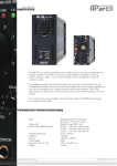
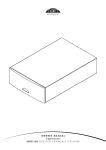
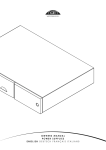
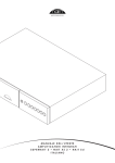
OWNERS MANUAL
SNAXO 362BMR, 362 & 242
ENGLISH • DEUTSCH
In t rod u ct io n
Naim Audio products are conceived with performance as the top priority. Careful
installation will help ensure that their full potential is achieved. This manual covers
the SNAXO active crossovers. It begins with some general installation notes. Product
specific information begins in Section 3.
1 Con n ect i on s
2.4 R a d i o In t e r f er e n c e
It is important for both safety and performance that
In some circumstances, depending on where you live
any standard cables supplied with Naim Audio
and the earthing arrangements in your home, you may
products are not modified.
experience radio frequency interference. Controls on
broadcasting in some territories allow very high levels of
1.1 In t er co n n e ct Ca b l e s
Interconnect plugs and sockets should be kept clean
and free from corrosion. The easiest way to clean them
is to switch off the equipment, pull the plugs out of their
sockets, and push them back in again. Contact cleaners
and “enhancers” should not be used as the film they
deposit may degrade the sound.
2 Gen er a l In s t a l l a t i on
Naim equipment is designed to offer the finest
performance possible avoiding compromise
wherever practical. This can lead to circumstances
that may be unfamiliar. The notes that follow contain
radio frequency radiation and both the choice and exact
siting of equipment may be critical. Susceptibility to radio
frequency interference is related to the wide internal
bandwidth necessary for high sound quality. A radio
frequency filter kit is available for some Naim equipment
but sound quality will be progressively compromised as
more elements of the kit are fitted.
2.5 L i g h t n i n g P r ec a u t i o n s
Your Naim hi-fi system can be damaged by lightning and
should be turned off and disconnected from the mains
when there is risk of lightning strike.
2.6 Pr ob l e ms ?
advice specifically related to Naim equipment as
Consumer protection varies from country to country. In
well as more general warnings about the use of
most territories a retailer must be prepared to take back
domestic audio products. Please read them carefully.
any equipment he has sold if it cannot be made to work
satisfactorily. A problem may be due to a fault in the
2.1 S i t i n g Th e E q u i p m en t
In order to reduce the risk of hum audible from the
loudspeakers, power supplies and power amplifiers
should be located a reasonable distance away from
other equipment. The maximum separation distance for
connected equipment is that allowed by the standard
interconnect lead.
2.2 S w i t c h i n g On
Source components and power supplies should be
switched on before power amplifiers. Always switch
system or its installation so it is essential to make full use of
your dealer’s diagnostic skills. Please contact your local
distributor, or Naim Audio directly, if any difficulties cannot
be resolved.
Some Naim equipment is made in special versions for
different territories and this makes it impracticable to
arrange international guarantees. Please establish the
local guarantee arrangements with your retailer. Contact
Naim Audio directly for help and advice if necessary.
2.7 S e r vi c e a n d Up d a t e s
amplifiers off and wait a minute before connecting or
It is essential that repairs and updates are only carried
disconnecting any leads. Always use the power switch on
out by an authorised Naim retailer or at the factory by
the product rather than a mains outlet switch.
Naim itself. Many components are custom made, tested
or matched and appropriate replacements are often
2.3 R u n n i n g In
Naim equipment takes a considerable time to run in
before it performs at its best. The duration varies, but under
some conditions the sound may continue to improve for
over a month. Better and more consistent performance
will be achieved if the system is left switched on for long
periods. It is worth remembering however that equipment
left connected to the mains can be damaged by
lightning.
unobtainable from other sources.
Direct contact to Naim for service or update information
should be made initially through Customer Services:
Tel:
Email:
+44 (0)1722 426600
[email protected]
Please quote the product serial number (found on its rear
panel) in all correspondence.
SN A XO Inst allat io n
3 S N A XO I n s t a l l a t i o n
The SNAXO active crossovers are designed to provide optimised active filter
characteristics for all active-capable Naim loudspeakers. They should be mounted
horizontally on an equipment stand intended for the purpose. It is important to ensure that
the stand is level.
SNAXO active crossovers contain no internal power supply and must be connected to a
dedicated Naim FlatCap, Hi-Cap or Supercap power supply.
The SNAXO 362BMR incorporates a suspension system to isolate its sensitive components
from vibrational energy. The suspension system is protected during shipping by two transit
screws. The transit screws must be removed before use. Once the transit screws are
removed the SNAXO must not be inverted. Transit screw removal is best carried out once
the SNAXO is installed in its final location and before connections are made.
3.1 S N A XO 362B MR T r a n s i t S cr ew s
Two transit screws must be removed from the underside
of the SNAXO 362BMR before use and replaced if it is to
be carried any distance, packed or shipped. Transit screw
removal is illustrated in Diagram 3.2. SNAXO 362BMR transit
screws must not be used with any other Naim product.
Damage may result if the SNAXO 362BMR is inverted either
during or after transit screw removal.
To gain access to the transit screws, position one end of
the SNAXO 362BMR over the edge of a table, remove (or
replace) the screw that becomes accessible and then
repeat with the other end.
3.2 Tr a n s i t S cr e w R e m ova l
3.3 Con n e ct i n g S N A XO
3.3.1 Power Supply
SNAXO active crossovers must be connected to a
dedicated Supercap, Hi-Cap or Flatcap power supply.
Connect the SNAXO to the dedicated power supply
using, in the case of a Hi-Cap or Flatcap, a Naim SNAIC
interconnect cable, and in the case of a Supercap, the
appropriate Burndy cable. In either case take care to
connect with the correct cable orientation.
Note: If the SNAXO Burndy power supply socket is not used,
the supplied Burndy link plug must be inserted. Similarly,
if the SNAXO DIN power supply socket is not used the
supplied dust cover should be fitted.
3.3.2 Signal Input
To ensure the appropriate signal earthing arrangements,
the input signal to a SNAXO active crossover is delivered
via its power supply. The diagrams on the following pages
front transit
screw
illustrate signal input connections.
3.3.3 Signal Outputs
SNAXO output signals are carried on 4-PIN DIN sockets.
The four or six output sockets should be connected to the
power amplifier input sockets as appropriate.
Each left and right filter output is available on two
separate DIN sockets to enable the use of both mono and
stereo power amplifiers.
Take care to ensure that SNAXO outputs and amplifier
inputs are correct with respect to loudspeaker drive units.
Incorrect connection may result in loudspeaker damage.
The diagrams on the following pages illustrate signal output
connections.
rear transit
screw
3.4 Ou t p u t Lev el A d ju st me n t
Filter output level adjustment is available via trim controls
within each SNAXO. When shipped the trim controls are set
nominally flat. Contact your retailer or local distributor for
information and advice on level adjustment.
1
SN A XO Co nnec t io n S oc ket s
4 S N A XO Con n ec t i o n S oc ket s
4.1 S N A XO 362B MR R e a r ( fo r Ova t or S -600 a n d S -4 00 o n l y)
Supercap
power supply
low frequency
1 output
Outputs
PSU/Input
ch1
nc
ch2
+ve
ch1
+ve
ch2
-ve
-ve
4.1.1 Loudspeaker Connections
low frequency
2 output
BMR output
Hi-Cap or Flatcap
power supply
SNAXO Output
Ovator S-600/S-400 Drive-unit
LF1
LF2
BMR
Upper bass drive-unit
Lower bass drive-unit
Balanced Mode Radiator
4.2 S N A XO 362 R ea r
Supercap
power supply
mid frequency
output
Outputs
PSU/Input
ch1
nc
ch2
+ve
ch1
+ve
ch2
-ve
-ve
4.2.1 Loudspeaker Connections
low frequency high frequency
output
output
Hi-Cap or Flatcap
power supply
SNAXO Output
Loudspeaker Drive-unit
LF
Bass drive-unit
MF
Mid-range drive-unit
HF
High-frequency drive-unit
4.3 S N A XO 242 R ea r
low/mid frequency
output
Supercap
power supply
Outputs
PSU/Input
ch1
nc
ch2
-ve
+ve
ch1
+ve
ch2
-ve
4.3.1 Loudspeaker Connections
high frequency
output
2
Hi-Cap or Flatcap
power supply
SNAXO Output
Loudspeaker Drive-unit
LF
HF
Bass/Mid-range drive-unit
High-frequency drive-unit
SN A XO Po wer S up p ly C o nnec t ion s
5 S N A XO Pow e r S u p p l y Con n ect i on s
5.1 S N A XO 242 co n n e c t e d t o Fl a t ca p XS
power
signal input (from preamplifier
power supply)
mains
input
and fuse
link plug fitted
cable
direction
marker
Interconnect Cables
240° 5 to 5 pin DIN
5.2 S N A XO 362 co n n e c t e d t o Hi -C a p
cable
direction
marker
mains input
and fuse
signal input (from
preamplifier power
supply)
Interconnect Cables
240° 5 to 5 pin DIN
link plug fitted
3
SN A XO Po wer Sup p ly C onnec t ions
5.3 S N A XO 362B MR c o n n ec t e d t o S u p er ca p
mains input
and fuse
signal input (from preamplifier
power supply)
cable
direction
marker
4
Interconnect Cables
SNAXO Burndy
SN A XO A m p lifier C o n nec t io ns
6 S N A XO A m p l i fi e r C on n e ct i on s
6.1 S N A XO 242 co n n e c t e d t o 2 x N A P2 50
cable
direction
marker
(white)
Interconnect Cables
4 pin DIN to XLR
Note: Connection to two NAP 150 XS or NAP 200s follows
the same principle as shown below but with 4 pin DIN
to 4 pin DIN cables.
mains input
and fuse
left
speaker HF
right
speaker HF
mains input
and fuse
left
speaker LF
right
speaker LF
5
SN A XO A m p lifier C o n nec t io ns
6.2 S N A XO 362 c on n e c t ed t o 3 x N A P250
cable
direction
marker
(white)
6
mains input
and fuse
left
speaker HF
right
speaker HF
mains input
and fuse
left
speaker MF
right
speaker MF
mains input
and fuse
left
speaker LF
right
speaker LF
Interconnect Cables
4 pin DIN to XLR
SN A XO A m p lifier C o n nec t io ns
6.3 S N A XO 362B MR c o n n ec t e d t o 2 x N A P25 0
cable
direction
marker
(white)
mains input
and fuse
left
speaker BMR
mains input
and fuse
left speaker LF1 &
LF2 via Naim Y-Link
speaker cable splitter
Interconnect Cables
4 pin DIN to XLR
right
speaker BMR
right speaker LF1 &
LF2 via Naim Y-Link
speaker cable splitter
Note: The Naim Y-Link speaker cable splitter enables
the twin low frequency drivers of a Naim Ovator S-400
or Ovator S-600 speaker to be driven from one amplifier
channel. Contact your local retailer or distributor for more
information.
7
SN A XO A m p lifier C o n nec t io ns
6.4 S N A XO 362B MR c o n n ec t e d t o 3 x N A P30 0
cable
direction
marker
(red)
cable
direction
marker
(green)
left
speaker BMR
8
right
speaker BMR
left
speaker LF1
right
speaker LF1
left
speaker LF2
right
speaker LF2
Interconnect Cables
4 pin DIN to XLR (right)
4 pin DIN to XLR (left)
SN A XO Sp ec ific at io ns
7 S N A XO S p ec i fi c a t i on s
S N A XO362B MR
S N A XO362
S N A XO242
Input Impedance
20kΩ
13kΩ
20kΩ
Nominal Input Level
775mV
775mV
775mV
Level Adjustment
+0db, -5dB
+0db, -5dB
+0db, -5dB
Filter Frequencies
400Hz, 3rd Order
300Hz, 3rd Order
3kHz, 3rd Order
3kHz, 3rd Order
Outputs
6 x 4 pin DIN
6 x 4 pin DIN
4 x 4 pin DIN
Nominal Output Level
775mV
775mV
775mV
Min Load Impedance
10kΩ
10kΩ
10kΩ
Power Supply Voltage
24V
24V
24V
Power Supply Options
FlatCap
FlatCap
FlatCap
Hi-Cap
SuperCap
Hi-Cap
SuperCap
Hi-Cap
SuperCap
Weight
7.25kg
3.20kg
3.20kg
Dimensions (H x W x D)
87 x 207 x 314mm
87 x 207 x 314mm
87 x 207 x 314mm
9