1
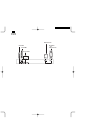
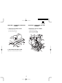
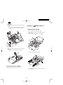
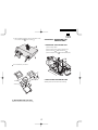
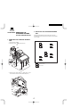
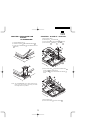
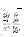
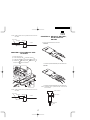
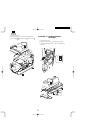
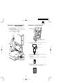
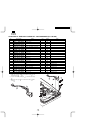
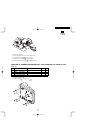
UP-600 MODEL UP-700 UP-700 UP-600 CONTENTS CHAPTER 1. REMOVING THE REAR COVER ............................................... 1 CHAPTER 2. REMOVING THE TOP CABINET............................................... 1 CHAPTER 3. REMOVING THE LCD UNIT ...................................................... 2 CHAPTER 4. REMOVING THE PRINTER UNIT ............................................. 3 CHAPTER 5. REMOVING THE STANDARD DRAWER unit (For KA, KB version) .................................................................. 4 CHAPTER 6. EXPANSION RAM BOARD : UP-S02MB/04MB ........................ 5 CHAPTER 7. IN-LINE I/F : UP-E10IN .............................................................. 5 CHAPTER 8. MCR UNIT : UP-E13MR............................................................. 6 CHAPTER 9. POLE DISPLAY UNIT : UP-P16DP............................................ 7 CHAPTER 10. RE-232 I/F : ER-A5RS, EFT & RS-232 I/F : ER-01EF ............. 7 CHAPTER 11. HAND SCANNER : ER-A6HS1 ................................................ 8 CHAPTER 12. REMOTE DRAWER : ER-04DW/05DW ................................... 9 CHAPTER 13. RS232DEVICES....................................................................... 9 CHAPTER 14. ONE HOLE CLERK KIT : DKIT-8669BHZZ (For UP-600) ..... 10 CHAPTER 15. DRAWER SEPARATION KIT : DKIT-3409BHZZ (For KA/KB version) ................................... 11 Parts marked with " " are important for maintaining the safety of the set. Be sure to replace these parts with specified ones for maintaining the safety and performance of the set. SHARP CORPORATION This document has been published to be used for after sales service only. The contents are subject to change without notice. >>>>> USE FONT <<<<< Helvetica/ Helvetica-Condensed/ Century-Schoolbook/ Symbol & OriginalFonts: (RingWorld2/RingFont2/Pa Symbol/PartsCod) - - - - - - - - - - - - - - - - - - - - - - - - - - - - - - - - - - - - - - - - - - - - - - - - - - - - - - - RS232 devices UP-P16DP UP-E13MR In-Line cable ER-A6HS1 and RS232 devices CHAPTER 1. REMOVING THE REAR COVER CHAPTER 2. REMOVING THE TOP CABINET 1. REMOVING THE REAR COVER 1. REMOVING THE TOP CABINET 1) Remove the two screws 2) Remove the rear cover . 1) Open the printer cover . . . 2) Lift the pop-up display unit 3) Remove the three screws 1 . 2 3 3 2 1 1 3 2. REPLACING THE REAR COVER Install the rear cover in the reverse order of removing. 4) Slightly lift and slide the top cabinet, and remove the grounding wire . Note: Do not pull up the top cabinet unit the grounding wire and connector cables from the top Cabinet are removed. CHAPTER 3. REMOVING THE LCD UNIT 1. REMOVING THE LCD UNIT 1) Remove the top cabinet from the bottom cabinet. 2) Remove the LCD flat cable CKDC PWB . 3) Remove the two screws and the earth wire from the LCD HINGE from the . 4 2 1 4 4 5 5) Remove the following cable between the top cabinet and the main PWB. Cable between the MAIN PWB and the CKDC PWB. 5 3 4) Remove the LCD unit from the top cabinet. 2. REPLACING THE TOP CABINET Install the top cabinet in the reverse order of removing. Insert a flat-bladed screwdriver into the right and left mounting areas and remove. 5) With a flat-bladed screwdriver, remove the two latches of each of the LCD rear cabinet and the LCD filer . 6 CHAPTER 4. REMOVING THE PRINTER UNIT 1. REMOVING THE PRINTER UNIT 1) Remove the top cabinet. 2) Remove the two screws fixed on the earth wire 3) Remove the screw 4) Remove the printer cable A 7 fixed on the printer unit. . from the MAIN PWB (CN9). 1 1 B 2 Turn of A and B when you remove it. 3 4 LCD volum PWB LCD HS unit LCD back light 2. REPLACING THE LCD UNIT Install the LCD unit in the reverse order of removing. 2. REPLACING THE PRINTER UNIT Install the printer unit in the reverse order of removing CHAPTER 5. REMOVING THE STANDARD DRAWER unit (For KA,KB version) 2. REPLACING THE STANDARD DRAWER UNIT Install the standard drawer unit in the reverse order of removing The drawer top has the following holes with which the drawer position can be changed. 1. REMOVING THE STANDARD DRAWER UNIT 1) Open the printer cover 2) Remove the screw . fixed on the drawe unit. 2 1 B 2 A : Standard position : Rear position 3) Stand the main drawer sideways as illusted above, and remove the drawer connector from the MAIN PWB (CN:5 ). DRCN2 CN4 CN5 CHAPTER 6. EXPANSION RAM BOARD : UP-S02MB/04MB 1) Open the ROM/RAM case 2) Install the two spacers CHAPTER 7. IN-LINE I/F : UP-E10IN 1) Remove the top cabinet. 2) Install the spacer 3) Connect the UP-E10IN . on the ROM/RAM PWB unit 3) Connect the UP-S02MB/04MB (CN:303) on the MAIN PWB . 4) Fix the UP-E10IN . to the MAIN PWB to the spacer (CN:304). with a screw . to the ROM/RAM PWB unit 4 3 1 1 2 3 through the two standard holder 5) Pass the TCP/IP cable and one core to the following PWB. 4 2 UP-E10IN side CN504 : CN3, MCR POLE RELAY PWB side 7 5 8 9 8 NOTE: The UP-S02MB/S04MB has an electric double layer capacitor (C21). When removing it after using, use caution not to bring it close to any conductor. 6 7) Remove the rear cover. 8) Connect the LAN cable to the LAN connector . : 9) Install the core to the LAN cable 4) Install the MCR unit 2 screws . . to the MCR angle 1 and secure with 11 10 4 4 3 12 NOTE: Install the ferrite core in a position less than 50 mm from the cabinet. Cabinet Core IN-LINE cable 6 Within 50mm 5 CHAPTER 8. MCR UNIT : UP-E13MR 1) Align the MCR sheet cabinet . with the positioning line of the top 5) Remove the rear cover. 6) Connect the MCR cable to the main chassis 7) Fix the earth wire 2) Mark 3 points of the asterisk mark on the MCR sheet . 8) Install the core two wire bands. to the MCR connector to the MCR cable 8 1 11 7 9 2 10 2 3) Aligning with the markings, secure the MCR angle 1 top cabinet with 3 screws . to the 12 . with a screw and earth wire . with NOTE: Install the ferrite core in a position less than 50 mm from the cabinet. MCR cable Wire band Wire band 1) Connect the extrnal cables to the I/F board. Cabinet Core CHAPTER 10. RS-232 I/F :ER-A5RS , EFT & RS-232 I/F: ER-01EF <ER-A5RS> Earth wire Within 50mm CHAPTER 9. POLE DISPLAY UNIT : UP-P16DP 1) Remove the rear cover. 2) Connect the display cable to the main chassis 3) Fix the earth wire 4) Install the core to the POLE connector to the display cable . with a screw and earth wire . . with two wire bands. Secure the core • Install the core (RC0RF6700BHZZ) to the cable with a band. <ER-01EF> 2 1 5 3 4 • Install the core (RC0RF6700BHZZ) to the cable with a band. 6 NOTE: Install ferrite core in a position less than 10 mm from the D-sub connector. NOTE: Install the ferrite core in a position less than 50 mm from the cabinet. MCR cable Wire band D-sub connector Wire band Within 10mm Cabinet Core Core Earth wire Within 50mm Wire band Cable 2) Remove the rear cover. 3) Insert the I/F PWB 4) Fix the I/F angle to the connector of the MAIN PWB to the main chassis with two screws . CHAPTER 11. HAND SCANNER : ER-A6HS1 1) Remove the rear cover. 2) Connect the scanner cable to the RS232 CH1 connector. 3) Change the slide switch to the +5V side of the RS232 Relay PWB unit. 3 +5V CI 1 2 S401 4 1 CHAPTER 12. REMOTE DRAWER : ER-04DW/05DW 1) Remove the bottom cabinet from the standard drawer unit. ( Only for KA/KB version) 2) Connect to the remote drawer cable tor of the MAIN PWB (CN:4 or CN5). 3) Fix the earth wire with a screw CHAPTER 13. RS232 DEVICES Moduler RJ45 connector to the drawer connec. D-SUB connector NOTE: Install the ferrite core in a position less than 10 mm from the RS232 connector. 1 RS232 connector Within 10mm 2 Core 3 Wire band Cable DRCN2 For the RS232 Relay PWB, the signals can be switched over according to the device to be connected. D-SUB connector With the switch: S401, the signal to Pin 9 can be switched over between +5 and CI. CN5 +5V CN4 CI S401 Modular RJ45 connector With the switches: S403/S404, the signal to Pin 4 can be switched over between CD, CI, VCC (+5V) and GND. CI GND CD S404 VSC S403 CHAPTER 14. ONE HOLE CLERK KIT : DKIT-8669BHZZ (For UP-600) No. PARTS CODE NAME Q’ty ONE HOLE CLERK KIT PRICE NOTE BP 1 Connector (5Pin) 1 AE 2 Connector (3Pin) 1 AD 3 Clerk switch body 1 BH 4 Clerk key cable (8pin) (For UP-600) 1 AL 5 Clerk angle (For UP-600) 1 AM 6 Screw 1 AA 7 Clerk cover "B" (For UP-600) 1 AH 8 Clerk key No.1 2 AW Clerk key No.2 2 AW Clerk key No.3 2 AW Clerk key No.4 2 AW Clerk key No.5 2 AW Clerk key No.6 2 AW Screw 1 AA UP-600:Not used Screw 2 AA UP-600:Not used Clerk key cable (5pin) 1 AN UP-600:Not used Clerk angle 1 AM UP-600:Not used "Clerk cover "B" 1 AG UP-600:Not used "Clerk cover "B" 1 AH UP-600:Not used 1) Solder the connector 5pin clerk switch body . and connector 3pin 2) Connect the clerk key cable 8pin . 3) Install the clerk angle screw . to the clerk switch body 7 4 to the clerk switch body 1 2 to the with a 3 4 4) Remove the top cabinet 5) Remove the standard clerk cover from the bottom cabinet. 6) Install the clerk cover "B" to the bottom cabinet. 7) Install the clerk switch body to the bottom cabinet. to the CKDC PWB (CN8) 8) Connect the clerk key cable 8pin CHAPTER 15. DRAWER SEPARATION KIT : DKIT-3409BHZZ (For KA/KB version) PARTS LIST No. PARTS CODE NAME Q’ty DRAWER SEPARATION KIT PRICE AP 1 Gum leg 4 AE 2 Screw 3 AA 3 Screw 1 AA 1) Remove the standard drawer. 2) Fix the four gum legs 1 with four screws 1 3 2 1 2 1 2 . COPYRIGHT 2001 BY SHARP CORPORATION All rights reserved. Printed in Japan. No part of this publication may be reproduced, stored in a retrieval system, or transmitted. In any form or by any means, electronic, mechanical, photocopying, recording, or otherwise, without prior written permission of the publisher. SHARP CORPORATION Digital Document Systems Group Quality & Reliability Control Center Yamatokoriyama, Nara 639-1186, Japan 2001 March Printed in Japan