1
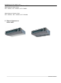
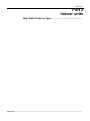
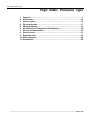
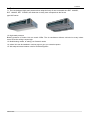
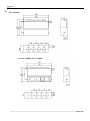
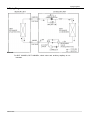
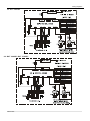
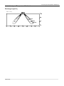
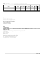
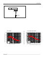
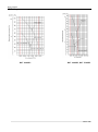
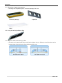
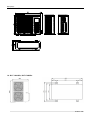
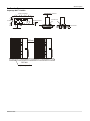
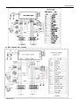
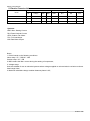
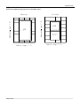
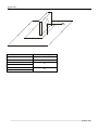
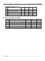
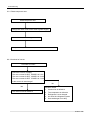
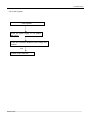
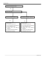
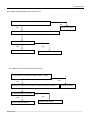
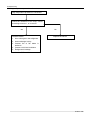
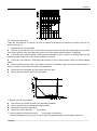
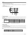
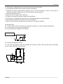
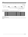
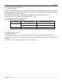
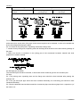
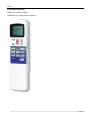
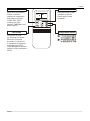
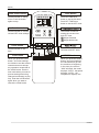
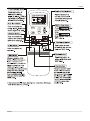
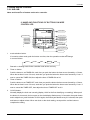
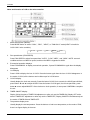
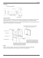
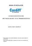
Service Manual MODEL: DCT 100HSPi-o DCT 140HSPi-o DCT 170HSPi-o Contents Part 1 General information…………………………………...……………… Part 2 Indoor units……………………………………………..……...……… Part 3 Outdoor units………………………………………………...………… Part 4 Installation…………………...………………………..……...………… Part 5 Control………………………………………………………...…………. Contents 1 General Information Part 1 General Information 1. Model names of Indoor/Outdoor Units………………… 2. External Appearance……………………………………… 3. Nomenclature……………………………………………… 4. Features…………………………………………………….. General Information Model Names of Indoor/ Outdoor Units 1. Model Names of Indoor/ Outdoor Units Model Names of Indoor Units: DCT 100HSPi, DCT 140HSPi, DCT 170HSPi Model Names of Outdoor Units: DCT 100HSPo, DCT 140HSPo, DCT 170HSPo 2. External Appearance Indoor units General Information Features 4. Features The dimension is really more compact than the former type MHA series; 4.2 High-static pressure; 4.3 Multi-blowing outlets, to satisfy your fitment’s needs; 4.4 Indoor Unit can be installed in various ways to give you a creative space; 4.5 We adopt universal outdoor units for R410A refrigerant. General Information Indoor units Part 2 Indoor units High Static Pressure Type………………………………….. Indoor units High static pressure type High Static Pressure Type 1. Features………………………………………………………………………….7 2. Dimensions…………………………………………………………………….14 3. Service space………………………………………………………………….16 4. Piping diagrams……………………………………………………………….17 5. Wiring diagrams……………………………………………………………….18 6. Air Velocity and Temperature Distributions………………………………29 7. Electric Characteristics………………………………………………………30 8. Sound Levels…………………………………………………………………..31 9. Exploded view…………………………………………………………………33 10. Static pressure………………………………………………………………...36 11. Accessories…………………………………………………………………….38 Indoor units Features 1. Features 1.1 The new designed high static pressure duct adopt the body of new concealed duct DCT 100HSPi, DCT 140HSPi, DCT 170HSPi; the dimension is really more compact than the former type HSP series. 1.2 High-static pressure Blowing pressure of Indoor Unit can reach 150Pa. The air conditioner delivers cold wind to every indoor corner even the ceiling is super-high. 1.3 Multi-blowing outlets, to satisfy your fitment’s needs. 1.4 Indoor Unit can be installed in various ways to give you a creative space. 1.5 We adopt universal outdoor units for R410A refrigerant. Indoor units Dimensions 2.Dimensions 2.2. DCT 100HSPi 2.3. DCT 140HSPi, DCT 170HSPi Indoor units Service space 3. Service space Note: Above figure means minimum value. Please keep these value at least. Indoor units Piping diagrams 4. Piping Diagrams Remark: For DCT 100HSPo, DCT 140HSPo, check valve and auxiliary capillary is not included. Indoor units Wiring diagrams 5.4. DCT 100HSPi 2.3. DCT 140HSPi, DCT 170HSPi Indoor units Air velocity and temperature distributions 6. Air Velocity and Temperature Distributions Discharge angle 60° Airflow velocity Indoor units Electric characteristics DCT 100HSPi, DCT 140HSPi, DCT 170HSPi 7. Electric Characteristics Units Model Hz Voltage Power supply Min. Voltage Max. Voltage MCA IFM MFA KW FLA DCT 100HSPi 50 380 342 418 0.9125 15 80 073 DCT 140HSPi 50 380 342 418 2.8125 15 350 DCT 170HSPi 50 380 342 418 2.8125 15 350 2,25 2,25 Symbols: MCA: Min. Circuit Amps(A) MFA: Max. Fuse Amps(See note 5) KW: Fan Motor Rated Output(KW) FLA: Full Load Amps IFM: Indoor Fan Motor Note: 1. Voltage range Units are suitable for use on electrical systems where voltage supplied to unit terminals is not below or above listed range limits; 2. Maximum allowable voltage unbalance between phases is 2%; 3. MCA/MFA MCA=1.25*FLA MFA<=4*FLA (Next lower standard fuse rating Min. 15A); 3. Select wire size based on the MCA; 5. Instead of fuse, use circuit breaker. Indoor units Sound levels 8. Sound Levels CONCEALED DUCT TYPE Duct 1.0m Sound pressure level dB (0dB=0.0002μ bar) DCT 100HSPi Audibility limits of continuous white sound Octave band center frequency(Hz) Indoor units Sound pressure level dB (0dB=0.0002μ bar) Microphone DCT 140HSPi, DCT 170HSPi Audibility limits of continuous white sound Octave band center frequency(Hz) Static pressure 10.Static pressure DCT 100HSPi DCT 140HSPi, DCT 170HSPi Indoor units Accessories 11. Accessories 11.1 Wild variety of optional accessories ---Including front clapboard, panel, canvas air passage, filter, etc. Canvas air passage Clapboard Panel 11.2 A long-life and high-efficiency filter 11.3 Way of air intake and inserting air filter ---Air intake can be positioned either at the back or below the unit. Similarly, the air filter also can be inserted either from the back or from the bottom of the unit. Indoor units Outdoor units Outdoor Units 1. Dimensions………………………………………………………………………41 2. Service Space……………………………………………………………………43 3. Wiring Diagrams………………………………………………………………...44 4. Field Wiring………………………………………………………………………47 5. Electric Characteristics………………………………………………………..48 6. Operation Limits………………………………………………………………...49 7. Sound Levels…………………………………………………………………….50 8. Exploded view…………………………………………………………………...52 9. Troubleshooting………………………………………………………………...60 Outdoor units Dimensions 1.3. DCT 100HSPo 1.4. DCT 140HSPo, DCT 170HSPo Outdoor units Service space 2. Service Space Capacity≤ DCT 170HSPo Obstacle >30cm Air inlet >30cm >60cm (Wall or obstacle) Air inlet Fix with bolt Maintain channel >200cm >60cm Air outlet Necessary width 600mm M10 bolt 4pieces per unit Outdoor units Deep foundation Wiring diagrams 3.4. DCT 100HSPi 3. 5. DCT 140HSPi, DCT 170HSPi Outdoor units Electric characteristics 5. Electric Characteristics Units Model Compressor OFM Hz Voltage Min. Max. MSC RLA KW FLA DCT 100HSPo 50 380 342 418 61 6.58 250 1.38 DCT 140HSPo 50 380 342 418 66 8.22 65 0.7 DCT 170HSPo 50 380 342 418 67 9.77 65 0.7 Symbols: MSC: Max. Starting Current RLA: Rated Locked Current OFM: Outdoor Fan Motor FLA: Full Load Amps. KW: Rate Motor Output Notes: 1. RLA is based on the following conditions: Indoor temp. 27℃ DB/19℃ WB Outdoor temp. 35℃ DB 2. MSC means the Max. current during the starting of compressor; 3. Voltage range Units are suitable for use on electrical systems where voltage supplied to unit terminals is not below or above listed range limits; 4. Maximum allowable voltage variation between phase is 2%; Outdoor units Operation limits 6. Operation Limits Ensure the operating temperature is in allowable range. Cooling Heating emp.(°C) STD 45 STD 35 17 Ambient 6 Ambient emp.(°C) 24 -7 -7 17 24 30 Indoor temp.(°C) Outdoor units With low ambient temp. cooling module 17 24 30 Indoor temp.(°C) Sound levels 7. Sound levels 1m Microphone Model Noise Level(dB(A)) 18000Btu/h 48 24000Btu/h 55 30000Btu/h 36000Btu/h 48000Btu/h 60000Btu/h 57 58 Outdoor units Troubleshooting 9. Troubleshooting 9.1 Indoor unit’s LED indication of trouble NO. Protection or Malfunction Operation Timer lamp lamp Defrosting lamp Auto recover 1 Indoor temp. sensor abnormal × ☆ × Yes 2 Indoor heat exchanger sensor abnormal ☆ × × Yes 3 Outdoor heat exchanger sensor abnormal × × ☆ Yes 4 Outdoor abnormal ☆ ☆ ☆ Yes 5 EEPROM abnormal ☆ ☆ × No ×——Extinguish ; ☆——Flash at 5Hz 9.2 LEDs’ for the indication of outdoor trouble DCT 100HSPo, DCT 140HSPo, DCT 170HSPo Type Contents LED1 LED2 LED3 Flash Off Off Off Off Flash Protection Phase sequence Protection Overload of current Protection Lack of phase Flash Off Off Protection Protection of pressure Flash Flash Off Protection Open-circuit and short-circuit trouble of T3 Off Flash Flash Protection Open-circuit and short-circuit trouble of T4 Off Flash Off Protection High temperature protection of condenser Flash Flash Flash Outdoor units Troubleshooting 9.2.1 Phase sequence error: Phase sequence error Change the order of two of the wires to power supply. Switch on the unit again. If the problem can not be solved, the outdoor PCB is defective 9.2.2 Overload of current Overload of current Check the current, normally The max. current for DCT 100HSPo is 9.4 A The max. current for DCT 140HSPo is 10.9A The max. current for DCT 170HSPo is 13.2A Is the current in rated range? No Yes The outdoor PCB is defective Possible reason 1. Outdoor fan is defective 2. The compressor is defective 3. Refrigerant is over charged 4. Air enter the refrigerant system 5. Heat exchanger is too dirty Outdoor units Troubleshooting 9.2.3 Lack of phase Lack of phase Check the power supply, is it 3 phase, 380-415V? is the voltage in outdoor terminal is 3 phase, Yes 380-415V? Check the connection between power supply and terminal, Yes Outdoor PCB is defective Outdoor units Troubleshooting 9.2.4 Protection of pressure or temp. Protection of pressure or temp. Yes Is it k1 or K2 open ? Is temp. protective switch K1 open Yes Possible reason 1. The wires is loose to K1 2. Air or other gas in the refrigerant. 3. Heat exchanger is dirty 4. Outdoor fan or fan blade is defective 5. Outdoor unit is bad ventilation 6. Refrigerant is leakage 7. K1 switch is defective Is pressure protective switch K2 open Yes Possible reason 1. The wires is loose to K2 2. Air or other gas in the refrigerant. 3. Heat exchanger is dirty 4. Outdoor fan or fan blade is defective 5. Outdoor unit is bad ventilation 6. Refrigerant is two much 7. K2 switch is defective Outdoor units Troubleshooting 9.2.5 Open-circuit and short-circuit trouble of T3 Is connection to connector of temp. sensor good? No Yes Repair connector Check the resistance of the temp. sensor according to Annex 1 Is it the resistance is normal? Yes Indoor PCB is defective. No Replace the sensor 9.2.6 Open-circuit and short-circuit trouble of T4 Is connection to connector of temp. sensor good? No Yes Check the resistance of the temp. sensor according to Annex 1 Is it the resistance is normal? Yes Indoor PCB is defective. Outdoor units No Replace the sensor Repair connector Troubleshooting 9.2.7 High temperature protection of condenser High temperature protection of condenser Check the resistance of the temp. sensor according to Annex 1, is it normal? Yes Possible reason 1. Air or other gas in the refrigerant. 2. Heat exchanger is dirty 3. Outdoor fan or fan blade is defective 4. Outdoor unit is bad ventilation 5. Refrigerant is leakage 6. Outdoor PCB is defective No Replace the sensor Outdoor units Troubleshooting 9.3 Troubles and Solutions If any the following abnormal conditions occur, turn off the power supply immediately. Please contact our dealer. TROUBLES Indicator lamps flash rapidly, after your disconnecting and connecting the unit, the situation is the same. Fuse or circuit breaker work frequently. Foreign matter or water has fallen into the unit. Remote controller is disabled or the switch is out of hand. Any other unusual conditioner is observed. If any of the following conditions occur, check your unit and resolve corresponding problems referring to given remediation. If the trouble can't be settled contact our dealer. Trouble Unit does not start Air flowing normally with low cooling(heating) effect Cause Solutions Power failure. Wait for the comeback of power Power switch is open. Switch on the power Fuse of power switch may have blown. Replace the fuse Batteries of remote controller are exhausted. Replace the batteries The time is not start-up time you have set. Wait or cancel the time set. Temperature is not set correctly. Set the temperature properly. Door or window is open. Close door and window. Air filter is blocked with dust or dirtiness. Clean the air filter. Inlet/outlet blocked. of indoor/outdoor units are Clear all blockages. Inlet/outlet blocked. of indoor/outdoor units are Clear the blockage, then restart your operation. Be in 3 minutes protection of compressor Wait NOTE: Do not replace electric wire or repair the air conditioner by yourself to avoid possible danger. 9.4 Troubles and solutions concerning the remote controller Please make the following check before asking for repair or maintenance. Trouble Cause Solutions CAN NOT CHANGE THE FAN SPEED SETTING Check if the mode display on the LCD is AUTO The lndoor Unit will select fan speed automatically when AUTO mode is selected. Check if the mode display on the LCD is DRY The lndoor Unit will select fan speed automatically when the unit is on DRY mode. The transmission symbol does not flash Symptom Checking items Cause Press ON/OFF button, the remote controlling signals can not be transmitted Check if the remote controller has run out of power When the battery was out, transmission signals can not be sent Outdoor units Troubleshooting Temperature display disappear Symptom Checking items Temperature Display does not light. Check if the mode display on the LCD is FAN ONLY Cause You can not set the temperature when the unit is on FAN ONLY mode. The Display Goes Off Symptom Checking items Cause The indication on the display disappears after a lapse of time. Check whether the timer operation has come to an end when the OFF TIMER is indicated on the display. The air conditioner operation stops since the set time elapsed. The ON TIMER indicators go off after a lapse of certain time. Check whether the timer operation is started when the ON TIMER is indicated on the display. When the time set to start the air conditioner is reached, the air conditioner will automatically start and the appropriate indicator will go off. The Signal Receiving Tone does Not Sound Symptom Checking items Cause No receiving tone sounds from the indoor unit even when the ON/OFF button is pushed. Check whether the signal transmitter of the remote controller is properly directed to the receiver of the indoor unit when the ON/OFF button is pushed. Direct the signal transmitter of the remote controller to the receiver of the indoor unit, and then repeatly push the ON/OFF button twice. Buttons on the remote controller don't work. Press Reset button. Outdoor units Installation Part 4 Installation Installation…………………………………………………… Installation Installation 1. Refrigerant pipe installation 1.1. Measure the necessary length of the connecting pipe, and make it by the following way. a. Connect the indoor unit at first, then the outdoor unit. Bend the tubing in proper way. Do not harm them. CAUTIONS: Daub the surfaces of the flare pipe and the joint nuts with frozen oil, and wrench it for 3~4 rounds With hands before fasten the flare nuts. Be sure to use two wrenches simultaneously when you connect or disconnect the pipes. Tubing size Torque 6.35 1420~1720N.cm(144~176kgf.cm) 9.52 3270~3990N.cm(333~407kgf.cm) 12.7 4950~6030N.cm(504~616kgf.cm) 16 6180~7540N.cm(630~770kgf.cm) 19 9720~11860N.cm(990~12106kgf.cm) b. The stop value of the outdoor unit should be closed absolutely (as original state). Every time you connect it, first loosen the nuts at the part of stop value, then connect the flare pipe immediately (in 5 minutes). If the nuts have been loosened for a long time, dusts and other impurities may enter the pipe system and may cause malfunction later. So please expel the air out of the pipe with refrigerant before connection. c. Expel the air after connecting the refrigerant pipe with the indoor unit and the outdoor unit. Then fasten the nuts at the repair-points. 1.2. Locate The Pipe a. Drill a hole in the wall (suitable just for the size of the wall conduit), then set on the fittings such as the wall conduit and its cover. b. Bind the connecting pipe and the cables together tightly with binding tapes. Do not let air in, which will cause water leakage by condensation. c. Pass the bound connecting pipe through the wall conduit from outside. Be careful of the pipe allocation to do no damage to the tubing. 1.3. Connect the pipes. 1.4. Then, open the stem of stop values of the outdoor unit to make the refrigerant pipe connecting the indoor unit with the outdoor unit in fluent flow. 1.5. Be sure of no leakage by checking it with leak detector or soap water. 1.6. Cover the joint of the connecting pipe to the indoor unit with the soundproof / insulating sheath (fittings), and bind it well with the tapes to prevent leakage. 2. Vacuum dry and leakage checking 2.1. Vacuum Dry: use vacuum pump to change the moisture (liquid) into steam (gas) in the pipe and discharge it out of the pipe to make the pipe dry. Under one atmospheric pressure, the boiling point of water(steam temperature) is 100℃. Use vacuum pump to make the pressure in the pipe near vacuum state, the boiling point of water falls relatively. When it falls under outdoor temperature, the moisture in the pipe will be vaporized. Installation Installation 2.2. Vacuum dry procedure There are two methods of vacuum dry due to different construction environment: common vacuum dry, special vacuum dry. ①. Common vacuum dry procedure Vacuum dry (for the first time)---connect the all-purpose detector to the inlet of liquid pipe and gas pipe, and run the vacuum pump more than two hours (the vacuum pump should be below -755mmHg) If the pump can’t achieve below -755mmHg after pumping 2 hours, moisture or leakage point will still exist in the pipe. At this time, it should be pumped 1 hour more. If the pump can’t achieve -755mmHg after pumping 3 hours, please check if there are some leakage points. Vacuum placement test: place 1 hour when it achieves -755mmHg, pass if the vacuum watch shows no rising. If it rises, it shows there’s moisture or leakage point. Vacuuming from liquid pipe and gas pipe at the same time. Sketch map of common vacuum dry procedure. ② Special vacuum dry procedure This vacuum dry method is used in the following conditions: There’s moisture when flushing the refrigerant pipe. Rainwater may enter into the pipe. Vacuum dry for the first time ······ 2h pumping ③. Vacuum destroy for the second time ······ Fill nitrogen to 0.5Kgf/cm2 Because nitrogen is for drying gas, it has vacuum drying effect during vacuum destroy. But if the Installation Installation moisture is too much, this method can’t dry thoroughly. So, please pay more attention to prevent water entering and forming condensation water. ④. Vacuum dry for the second time······1h pumping Determinant: Pass if achieving below -755mmHg. If -755mmHg can’t be achieved in 2h, repeat procedure ③ and ④. ⑤. Vacuum placing test ······ 1h ⑥. Sketch map of special vacuum dry procedure 3. Additional charge 3.1. When the length of the one-way pipe is less than 5m, additional refrigerant charge after vacuuming is unnecessary. 3.2. When the length of one-way pipe is over 5m, the additional charge quantity is as follows (unit in gram): Calculation method Refrigerant R410A Liquid diameter(mm) Unit amount (g/m) Formula Φ6.35 30 (L-5)×22 Φ9.53 65 (L-5)×60 Φ12.7 90 (L-5)×110 Remark:1、The additional refrigerant charge is simply related with the liquid pipe diameter. 2、In the up formula, “L” means total length of liquid pipe(unit: m). 4. Water drainage 4.1. Gradient and Supporting 4.1.1 Keep the drainpipe sloping downwards at a gradient of at least 1/100. Keep the drainpipe as short as possible and eliminate the air bubble. 4.1.2 The horizontal drainpipe should be short. When the pipe is too long, a prop stand must be installed to keep the gradient of 1/100 and prevent bending. Refer to the following table for the specification of the prop stand. Hard PVC pipe Diameter Distance between the prop stands 25~40mm 1.5~2m Installation Installation 4.1.3. Precautions ① The diameter of drainpipe should meet the drainage requirement at least. ② The drainpipe should be heat-insulated to prevent atomization. ③ Drainpipe should be installed before installing indoor unit. After powering on, there is some water in water-receiver plate. Please check if the drain pump can operate correctly. ④ All connection should be firm. ⑤ Wipe color on PVC pipe to note connection. ⑥ Climbing, horizontal and bending conditions are prohibited. ⑦The dimension of drainpipe can’t less than the connecting dimension of indoor drainpipe. ⑧ Heat-insulation should be done well to prevent condensation. ⑨Indoor units with different drainage type can’t share one convergent drainpipe. 4.2 Drainpipe Trap 4.2.1. If the pressure at the connection of the drainpipe is negative, it needs to design drainpipe trap. 4.2.2. Every indoor unit needs one drainpipe trap. 4.2.3. A plug should be designed to do cleaning. 50cm 50cm P l u g 4.3 Upwards drainage(drain pump) 4.3.1. To ensure the gradient 1/100, the drainpipe can be lifted to 340mm. After upwards, place downwards, or it will cause malfunction to drain pump. Installation Installation 4.4 Convergent drainage 4.4.1. The number of indoor units should be as small as possible to prevent the traverse main pipe overlong. 4.4.2. Indoor unit with drain pump and indoor unit without drain pump should be in different drainage system. 4.4.3. Selecting the diameter Number of connecting indoor units→Calculate drainage volume→Select the diameter Calculate allowed volume =Total cooling capacity of indoor units(HP)×2 (l/ hr) Allowed volume(lean 1/100) (l/ hr) I.D. (mm) Thick Hard ∽≤14 3.0 ¢25 集中排水 Hard 3.5 14<∽≤88 ¢30 PVC 管 Hard 4.0 88<∽≤334 ¢40 PVC Hard 4.5 175<∽≤334 ¢50 PVC Hard 6.0 334<∽ ¢80 PVC PVC 4.5 Drainage test Drainage without drain pump After finishing drainpipe installation, pour some water into the water receiver plate to check if the water flows smoothly. Installation Installation 5. Insulation work 5.1 Insulation material and thickness 5.1.1. Insulation material Insulation material should adopt the material which is able to endure the pipe’s temperature: no less than 70℃ in the high-pressure side, no less than 120℃ in the low-pressure side(For the cooling type machine, no requirements at the low-pressure side.) Example: Heat pump type----Heat-resistant Polyethylene foam (withstand above 120℃) Cooling only type---- Polyethylene foam (withstand above 100℃) 5.1.2. Thickness choice for insulation material Insulation material thickness is as follows: Refrigerant pipe Drainage pipe Pipe diameter (mm) Adiabatic material thickness Φ6.4—Φ25.4 10mm Φ28.6—Φ38.1 15mm Inner diameterΦ20—Φ32 6mm 5.2 Refrigerant pipe insulation 5.2.1. Work Procedure ① Before laying the pipes, the non-jointing parts and non-connection parts should be heat insulated. ② When the gas proof test is eligible, the jointing area, expanding area and the flange area should be heat insulated 5.2.2. Insulation for non-jointing parts and non-connection parts Installation Installation wrong Gas pipe and liquid pipe should not be put together to insulate right Insulate the gas pipe (cooling only) Insulate the gas pipe and liquid pipe For construction convenience, before laying pipes, use insulation material to insulate the pipes to be deal with, at the same time, at two ends of the pipe, remain some length not to be insulated, in order to be welded and check the leakage after laying the pipes. 5.2.3. Insulate for the jointing area, expanding area and the flange area ① Insulate for the jointing area, expanding area and the flange area should be done after checking leakage of the pipes ② Make sure there’s no clearance in the joining part of the accessorial insulation material and local preparative insulation material. 5.3 Drainage pipe insulation The connection part should be insulated, or else water will be condensing at the non-insulation part. 5.4 Note 5.4.1 The jointing area, expanding area and the flange area should be heat insulated after passing the pressure test 5.4.2 The gas and liquid pipe should be heat insulated individually, the connecting part should be heat insulated individually. 5.4.3 Use the attached heat-insulation material to insulate the pipe connections (pipes’ tie-in ,expand nut ) of the indoor unit Installation Control Part 5 Control Control………………………………………………………... Control Control 1. Remote controller There’s one model R11HG/E. The below is R11HG/E remote controller. Control Control Mode select button Each time you push the button, a mode is selected in a sequence that goes from AUTO, COOL, DRY, HEAT (cooling only type without), FAN ONLY and back to AUTO. Fan button This button is used for selecting fan speed. Each time you push the button, a fan speed is selected in a sequence that goes from AUTO, LOW, MED(Some models without, HIGH, and back to AUTO. Control I/O Button Push the button to start operation, push the button again to stop operation. Temperature Button Control After Sliding the cover, the button and function are as follows: Auto louver button Timer button Push this button to swing louver. Push the button again to stop. Push ON-TIME timer button to set the ON timer. Push OFF-TIME timer button to set the OFF timer. Confirmation button Push this button to confirm ON and OFF timer settings. FAN This button is used for setting the current time and OFF time. Adjust forwards Adjust backwords Clock button Push this button to set time. Lock button When you push the LOCK button, all current settings are locked in and the remote controller does not accept any operation except that of the LOCK button. Use the lock mode when you want to prevent setting from being changed accidentally or play fully. Push the LOCK button again when you want to cancel the LOCK mode. Push this button to cancel ON timer and OFF timer. RESET button When you push the RESET button, all current settings are cancelled and get into the condition of beginning. In the clock, the colon in "0:00" will flash, the mode displays "AUTO", fan speed displays "AUTO", the temperature displays "24". Control Control Control Controller 3.2 Wired Remote Controller 3.2.1 KJR-10B I Name and functions of buttons on the wire controller 6. NAME AND FUNCTIONS OF BUTTONS ON WIRE CONTROLLER ON / OFF button Mode selection button ķ Fan speed selection Timer on button ĸ TIMER ON Timer off button Ĺ OK TIMER OFF CONFIRM Clock button ĺ confirm button Ok button Ļ replace nutton Reset button ļ Adjust button ▲ ECONOMICAL CLOCK MODE FAN SPEED SWING Adjust button ▼ TEMP Swing button REPLACE LOCK RESET COOL HEATING Economical button COOL ONLY/COOL and Heating selection button Lock button 1 mode selection button: 5 It is used to select mode, push the button one time, then the operation modes will change In turn as follows: AUTO COOL DRY HEAT FAN Remark: no heating mode if wire controller is set as the cool only. 2 Timer on button: Push the button to set TIMER ON, each time you push the button the time moves forward by o.5 hours. When the set time is over 10 hours, each time you push the button the time moves forward by 1 hour. If want to cancel the TIMER ON, then adjust the time of TIMER ON as 0.0 3 Timer off button: Push the button to set TIMER OFF, each time you push the button the time moves forward by o.5 hours. When the set time is over 10 hours, each time you push the button the time moves forward by 1 hour. If want to cancel the TIMER OFF, then adjust the time of TIMER OFF as 0.0 4 CLOCK button: Normally display the clock set currently (display 12:00 for the first electrifying or resetting). When push the button for 4 seconds, the hour part on the clock display flashes every 0.5 seconds, then push button and to adjust hour; push the button CLOCK again, the minute part flashes every 0.5 seconds, then push and button to adjust minute. When set clock or alter clock setting, must push the confirm button to complete the setting Electrical Control System Controller Name and function of LCD on the wire controller 1 Mode select button (MODE): Press MODE button to select “COOL”, “DRY” , "HEAT", or "FAN ONLY" mode.(HEAT is invalid for COOL ONLY wire controller.) AUTO 2 COOL DRY HEAT FAN Fan speed button (FAN SPEED) Press FAN SPEED to select fan speed from "AUTO", "LOW"," MED" , and "HIGH”. NOTE: some air conditioners have no MED fan speed, and then the MED is regarded as HIGH. 3 Economical operation displays: Press ECONOMICAL to display economical operation, if press ECONOMICAL again then the display disappears 4 Lock display Press LOCK to display the icon of LOCK. Press the button again then the icon of LOCK disappears. In the mode of LOCK, all the buttons are invalid except for LOCK button. 5 CLOCK display. Usually display the clock set currently. Press the button CLOCK for 4 seconds, the HOUR part will flash, press button Ÿ and ź to adjust HOUR. Press the button CLOCK again, the minute part flash, press buttonŸ orź to adjust MINUTE. After clock set or clock operation, it must press CONFIRM to complete the set. 6 TIMER ON/OFF display: Display ON at the state of TIMER ON adjustment or after only set the TIMER ON; Display OFF at the state of TIMER OFF adjustment or after only set the TIMER OFF; Display ON/OFF if simultaneously set the mode of TIMER ON and TIMER OFF. 7 Temperature display area: Usually display the set temperature. Press the buttons of and to set temperature, at the mode of FAN, there is no figure display in the area. Electrical Control System Controller Installation Installation Notice: When the air conditioner needs the constant frequency wire Controller, be sure adding a Wire Joint with 5 terminal named A, B, C, D, E in indoor unit, and fixing a infrared emitter whose anode and cathode connecting with A and B near the receiver in the Indoor Unit Switch Board, then connecting the terminal +5v, GND, Run in the Switch Board to C,D,E respectively. NOTE Never turn screws too tightly, or else the cover would be dented or the Liquid Crystal breaks. Please leave enough long cable for maintenance of the Wire Controller Board. Electrical Control System