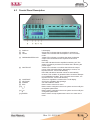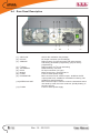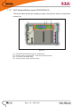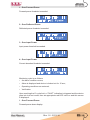
1
ATVCA USER MANUAL Manufactured by R.V.R ELETTRONICA S.p.A. Italy File Name: 03_ATVCA 2_ING_1.0.indd Version: 1.0 Date: 22/11/2010 Revision History Date Version 22/11/2010 1.0 Reason First Version Editor J. H. Berti ATVCA - User Manual Version 1.0 © Copyright 2010 R.V.R. Elettronica SpA Via del Fonditore 2/2c - 40138 - Bologna (Italia) Telephone: +39 051 6010506 Fax: +39 051 6011104 Email: [email protected] Web: www.rvr.it All rights reserved Printed and bound in Italy. No part of this manual may be reproduced, memorized or transmitted in any form or by any means, electronic or mechanic, including photocopying, recording or by any information storage and retrieval system, without written permission of the copyright owner. ATVCA Table of Contents 1. 2. 3. 3.1 3.2 4. 4.1 4.2 4.3 4.4 4.5 4.6 5. 5.1 5.2 6. 6.1 6.2 6.3 7. 7.1 7.2 8. 8.1 Preliminary Instructions Warranty First Aid Treatment of electrical shocks Treatment of electrical Burns General Description Unpacking Features Frontal Panel Description Rear Panel Description Connector Description Technical Description Setting Setting on air Setting on lab Start Up Important to Know Quick Start On Air Hardware Identification of the Modules Descriptions Firmware Descriptions User Manual Rev. 1.0 - 22/11/10 1 1 2 2 2 3 3 3 5 6 7 9 10 10 10 11 11 12 13 15 15 17 21 21 ATVCA This page was intentionally left blank ii Rev. 1.0 - 22/11/10 User Manual ATVCA IMPORTANT The symbol of lightning inside a triangle placed on the product, evidences the operations for which is necessary gave it full attention to avoid risk of electric shocks. The symbol of exclamation mark inside a triangle placed on the product, informs the user about the presence of instructions inside the manual that accompanies the equipment, important for the efficacy and the maintenance (repairs). 1. Preliminary Instructions WIRING: This device has a connection to ground on the power cord and on the chassis. Check that they are correctly connected. • General foreword Operate with this device in a residential ambient can cause radio disturbs; in this case, it can be demanded to the user to take adequate measures. The equipment in object is to considering for uses, installation and maintenance from “trained” or “qualified” staff, they conscious of the risks connected to operate on electronic and electrical circuits electrical. The “trained” definition means staff with technical knowledge about the use of the equipment and with responsibility regarding the own safety and the other not qualified staff safety place under his directed surveillance in case of works on the equipment. The “qualified” definition means staff with instruction and experience about the use of the equipment and with responsibility regarding the own safety and the other not qualified staff safety place under his directed surveillance in case of works on the equipment. Specifications and informations contained in this manual are furnished for information only, and are subject to change at any time without notice, and should not be construed as a commitment by R.V.R. Elettronica SpA. The R.V.R. Elettronica SpA assumes no responsability or liability for any errors or inaccuracies that may appear in this manual, including the products and software described in it;and it reserves the right to modify the design and/or the technical specifications of the product and this manual without notice. • Warning regarding the use designated and the use limitations of the product. WARNING: The machine can be equipped with an ON/OFF switch which could not remove completely voltages inside the machine. It is necessary to have disconnected the feeding cord, or to have switched off the control panel, before to execute technical operations, making sure himself that the safety connection to ground is connected. The technical interventions that expect the equipment inspection with circuits under voltage must be carry out from trained and qualified staff in presence of a second trained person that it is ready to intervene removing voltage in case of need. R.V.R. Elettronica SpA doesn’t assume responsibility for injury or damage resulting from improper procedures or practices by untrained/unqualified personnel in the handling of this unit. This product is an transmitter radio indicated for the audio broadcasting service in frequency modulation. It uses working frequencies that are not harmonized in the states of designated user. The user of this product must obtain from the Authority for spectrum management in the state of designated user the appropriate authorization to use the radio spectrum, before putting in exercise this equipment. The working frequency, the transmitter power, let alone other specifications of the transmission system are subject to limitation and definited in the authorization obtained. 2. Warranty R.V.R. Electronics S.P.A. guarantees absence of manufacturing defect and the good operation for the products, within the provided terms and conditions. WARNING: The equipment is not water resistant and an infiltration could seriously compromise its correct operation. In order to prevent fires or electric shocks, do not expose the equipment to rain, infiltrations or humidity. Please read the terms carefully, because the purchase of the product or acceptance of order confirmation, constitutes acceptance of the terms and conditions. Please observe all local codes and fire protection standards during installation and use of this unit. Warranty will be void in cases of opened products, physical damage, misuse, modification, repair by unauthorised persons, carelessness and using the product for other purpose than its intended use. WARNING: The equipment has to its inside exposed parts to risk of electric shock, always disconnect power before opening covers or removing any part of this unit. Fissures and holes are supplied for the ventilation in order to assure a reliable efficacy of the product that for protect itself from excessive heating, these fissures do not have to be obstructed or to be covered. The fissures doesn’t be obstructed in no case. The product must not be incorporated in a rack, unless it is supplied with a suitable ventilation or that the manufacturer’s instructions are been followed. WIRING: This equipment can irradiate radio frequency energyand if it’s not installed following the instructions contained in the manual and local regulations it could generate interferences in radio communications. User Manual For the last legal terms and conditions, please visit our web site (WWW.RVR.IT) wich may also be changed, removed or updated for any reason without prior notice. In case of defect, proceed like described in the following: 1 Contact the dealer or distributor where you purchased the unit. Describe the problem and, so that a possible easy solution can be detected. Dealers and Distributors are supplied with all the information about problems that may occur and usually they can repair the unit quicker than what the manufacturer could do. Very often installing errors are discovered by dealers. 2 If your dealer cannot help you, contact R.V.R. Elettronica and explain the problem. If it is decided to return the unit to the factory, R.V.R. Elettronica will mail you a regular authorization with all the necessary instructions to send back the goods; 3 When you receive the authorization, you can return the unit. Pack it carefully for the shipment, preferably using the original packing and seal the package perfectly. The customer always assumes the risks of loss (i.e., Rev. 1.0 - 22/11/10 / 32 ATVCA R.V.R. is never responsible for damage or loss), until the package reaches R.V.R. premises. For this reason, we suggest you to insure the goods for the whole value. Shipment must be effected C.I.F. (PREPAID) to the address specified by R.V.R.’s service manager on the authorization DO NOT RETURN UNITS WITHOUT OUR AUTHORIZATION AS THEY WILL BE REFUSED 4 Be sure to enclose a written technical report where mention all the problems found and a copy of your original invoice establishing the starting date of the warranty. Figure 5 Replacement and warranty parts may be ordered from the following address. Be sure to include the equipment model and serial number as well as part description and part number. R.V.R. Elettronica SpA Via del Fonditore, 2/2c 40138 BOLOGNA ITALY Tel. +39 051 6010506 3. First Aid The personnel employed in the installation, use and maintenance of the device, shall be familiar with theory and practice of first aid. 3.1 3.1.1 3.1.2 • In case of only one rescuer, 15 compressions alternated to two breaths. • If there are two rescuers, the rythm shall be of one brath each 5 compressions. • Do not interrupt the rythm of compressions when the second person is giving breath. • Call for medical assistance as soon as possible. If victim is responsive • Keep them warm. • Keep them as quiet as possible. Treatment of electrical shocks • Loosen their clothing (a reclining position is recommended). If the victim is not responsive • Call for medical help as soon as possible. Follow the A-B-C’s of basic life support. • Place victim flat on his backon a hard surface. • Open airway: lift up neck, push forehead back 3.2 3.2.1 (Figure 1). clear out mouth if necessary and observe for breathing • if not breathing, begin artificial breathing (Figure 2): tilt head, pinch nostrils, make airtight seal, four quick full breaths. Remember mouth to mouth resuscitation must be commenced as soon as possible. Extensive burned and broken skin • Cover area with clean sheet or cloth. • Do not break blisters, remove tissue, remove adhered particles of clothing, or apply any salve or ointment. • Treat victim for shock as required. • Arrange transportation to a hospital as quickly as possible. • If arms or legs are affected keep them elevated. If medical help will not be available within an hour and the victim is conscious and not vomiting, give him a weak solution of salt and soda: 1 level teaspoonful of salt and 1/2 level teaspoonful of baking soda to each quart of water (neither hot or cold). Figure 1 • Treatment of electrical Burns Allow victim to sip slowly about 4 ounces (half a glass) over a period of 15 minutes. Discontinue fluid if vomiting occurs. DO NOT give alcohol. 3.2.2 Less severe burns • Apply cool (not ice cold) compresses using the cleansed available cloth article. • Do not break blisters, remove tissue, remove adhered particles of clothing, or apply salve or ointment. • Apply clean dry dressing if necessary. • Treat victim for shock as required. • Arrange transportation to a hospital as quickly as possible. • If arms or legs are affected keep them elevated. Figure 2 • Check carotid pulse (Figure 3); if pulse is absent, begin artificial circulation (Figure 4) depressing sternum (Figure 5). Figure 3 / 32 Figure 4 Rev. 1.0 - 22/11/10 User Manual ATVCA 4. General Description The ATVCA is an analog TV broadcasting amplifier manufactured by R.V.R. Elettronica SpA delivering up to 1000 WPS under 50 Ohm standard load and less than 100W drive power requirement. The ATVCA has been designed for installation in a 19”x3HE box for rack. 4.1 Unpacking The package contains: 1 ATVCA 1 User Manual 1 Mains power cable The following accessories are also available from Your R.V.R. Dealer: • Accessories, spare parts and cables 4.2 Features Two major features of ATVCA are compact design and user-friendliness. Another key feature is its modular-concept design: the different functions are performed by modules with most connections achieved through male and female connectors or through flat cables terminated by connectors. This design facilitates maintenance and module replacement. The RF power section uses two moduls amplifier. Each one is able to deliver up to 500Wps. An LCD on the front panel and a push-button panel provide for user interfacing with the microprocessor control system, which implements the following features: • Power output enable/disable • User-selectable threshold settings for output power alarm (Power Good feature) • Measurement and display of amplifier’s operating parameters • Communication with external devices, as programming systems or telemetry systems through RS232 or I2C serial interface Four LEDs on the front panel provide for machine status indication (ON, LOCAL, WARNING INTERLOCK, WAIT FAULT). The amplifier management software is based on a menu system. User has four navigation buttons available to browse submenus: ESC, , , and ENTER. User Manual Rev. 1.0 - 22/11/10 / 32 ATVCA The rear panel features the mains input connectors, RF power input and output connectors, remote connector, protection fuse, interlock input and interlock output connectors and a BNC connector that provides an RF test point with a level suitable to execute the measurement. / 32 Rev. 1.0 - 22/11/10 User Manual ATVCA 4.3 Frontal Panel Description [1] DISPLAY [2] ON [3] LOCAL [4] WARNING/INTERLOCK [5] WAIT/FAULT [6] CONTRAST [7] AIR FLOW [8] POWER [9] ESC [10] [11] [12]ENTER User Manual LCD display. Green LED: indicates that the amplifier is switched on. Yellow LED: indicates that the amplifier is in local control mode. Yellow LED: indicates a condition that doesn’t inhibit the output of the transmitter and is reported via GUI and telemetry. Red LED: indicates that the amplifier is switching off. This status is caused by an external condition that is blocking the power output. Yellow LED: indicates a condition that inhibits the output power of the transmitter before attempting to restore, it is reported via GUI, TC/TS and telemetry. Red LED: indicates a fault that cannot be automatically reverted. This condition is generated after 10 restore attempts from WARNING condition, and it can block the machine; it is reported via GUI, TC/TS and telemetry. Trimmer to regulate the contrast of the LCD display. Grill for the ventilation flow passage. AC mains ON/OFF switch. Button used to exit from a menu. Button used to navigate in the menu system and to modify the changeable parameters. Button used to navigate in the menu system and to modify the changeable parameters. Button used to accept a parameter’s value or to enter into a menu. Rev. 1.0 - 22/11/10 / 32 ATVCA 4.4 Rear Panel Description [1] AIR FLOW [2] RF OUT [3] SERVICE [4] [5] [6] [7] [8] [9] I2C BUS TELEMETRY RF IN MAINS FUSE 1 RF MONITOR [10]INTERLOCK OUT [11] FUSE 2 / 32 Grill for the ventilation flow passage RF output connector (7/8” EIA flange) DB9 connector for interconnection with other devices and factory parameters programming (only for factory programming). DB9 connector for I2C bus networking DB25 telemetry connector RF input connector (“N” type) Mains supply plug, 1230V 50-60 Hz Fuse for mains power supply. BNC connector for RF monitor output, -60 dB wrt the RF output power level, suitable for modulation monitoring. Not suitable for spectral analysis. BNC interlock output connector: when the transmitter enters into stand-by mode, the inner conductor, tipically floating, is forced to ground. Fuse for mains power supply. Rev. 1.0 - 22/11/10 User Manual ATVCA 4.5 Connector Description 4.5.1 Telemetry Connector Type: DB25 Female 1 2 3 4 5 6 7 8 9 10 11 12 13 14 15 16 17 18 19 20 21 22 23 24 25 Internal SWR Disabled RF power amplifier voltage 3,9V x 50V GND GND Reflected Power 3,9V x 100W Interlock Set 4 GND GND “On” Command Set 1 WAIT Reset alarm OFF Interlock Temperature 3.9V x 100° RF power amplifier current 3.9V x 60A Forward Power 3,9V x 1000WPS FAULT Set 3 Input power 3,9V x 0dB “OFF” Command GND GND Set 2 LOC +Vcc ON 4.5.2 Service Type: DB9 female User Manual 1 2 3 4 5 6 7 8 9 NC TX_D RX_D Internally connected with 6 GND Internally connected with 4 Internally connected with 8 Internally connected with 7 NC Rev. 1.0 - 22/11/10 / 32 ATVCA 4.5.3 I2C Connector Type: DB9 Female 1 2 3 4 5 6 7 8 9 / 32 NC SDA SCL NC GND NC NC NC NC Serial Data Serial Clock GND Rev. 1.0 - 22/11/10 User Manual ATVCA 4.6 Technical Description ATVCA1K0LU1 Parameters Frequency range Rated output power Input power for rated output Power supply type AC Supply Voltage DC Supply Voltage AC Apparent Power Consumption Active Power Consumption RF Fan active Power consumption RF module efficiency Overall efficiency Input device Display Overall Phisical Dimensions Ambient working temperature Spurious & harmonic suppression Conditions U.M. MHz W W PS Mains input voltage range CPU backup Input Voltage Front panel width Front panel height Overall depth VAC VDC VA W W % % mm HE mm °C dBc Notes GENERALS 470-860 1000WPS 0dBm monophase/biphase 230 +10% -15%(*) about 2080 Measured on monophase 230V about 2060 Measured on monophase 230V 80 Measured on monophase 230V 59 con red field 50 5 pushbutton Alphanumerical LCD - 2 x 16 Only for PA Measured on monophase 230V 483 (19") 3 655 0 to + 45 In according to output filter Meets or exceeds all FCC and CCIR rules RF INPUT RF Input Connector Impedance Driver power for rated output Max input power before protection Ohm W W N type 50 0dBm 50 RF OUTPUTS RF Output RF Monitor Connector Impedance Connector Impedance Output Level Ohm Ohm dB 7/8"flange type 50 BNC 50 approx. -60 Referred to the RF output AUXILIARY CONNECTIONS Interlock Output RS232 Serial Interface Com Bus I2Cbus Telemetry Interface RS485 Serial Interface Remote Interface AUX power supply Connector Connector Connector Connector Connector Connector Connector Connector BNC DB9F DB15M DB9F DB25F Factory reserved for firmware program / configuration Factory reserved for coupling purposes POWER REQUIREMENTS AC Power Input DC Power Input AC Supply Voltage VAC 230 +10% -15%(*) (*) monophase (**) Threephases Y AC Apparent Power Consumption VA 2080 Measured on monophase 230V Active Power Consumption Power Factor Connector DC Supply Voltage DC Current W 2060 0,99 Morsettiera Measured on monophase 230V Measured on monophase 230V VDC mADC FUSES On Mains 2 External fuses F25T 10x38 (Threephases 230V) On services On AUX Power supply On P.A. Supply On fans Supply MECHANICAL DIMENSIONS Phisical Dimensions Front panel width Front panel height Overall depth Chassis depth Weight mm mm mm mm kg 483 132 655 650 code code code code 30dB to enter with 1W 19" EIA rack OPTIONS Internal Attenuator TELEMETRY / TELECONTROL Telemetry connector inputs Telemetry connector outputs Pulse Pulse Pulse Analogical level Analogical level Analogical level Analogical level Analogical level Analogical level Analogical level Open Collector Open Collector Open Collector Open Collector Open Collector Open Collector Open Collector Open Collector ON / OFF level Command ON Command OFF Alarm Reset FWD power REF power Internal SWR Input power VPA IPA Temperature Status ON Status OFF Power Good 1 Power Good 2 SWR Wait Fault Local Interlock 3,9V x 1000Wps 3,9V x 100W Disabled 3,9V x 0dB 3,9V x 50V 3,9V x 60A 3,9V x 100°C TELEMETRY-TELECONTROL SW Telecon VARIOUS Cooling type Potenza dissipata in calore Acoustic Noise Forced with internal fans W dBA 1500 with red pattern <75dBA Leq 3 min @ 1 m STANDARD COMPLIANCE Safety EMC Spectrum Optimization User Manual EN60215:1989 EN 301 489-11 V1, 2, 1 Rev. 1.0 - 22/11/10 / 32 ATVCA 5. Setting 5.1 Setting on air 1. Connect the RF output power of a suitable TV exciter (e.g. the DTVPE of R.V.R. Elettronica) to the RF input (RF module) using a cable fitted with N type connectors. The exciter should be set to minimum output power and switched OFF. 2. Connect the amplifier’s INTERLOCK output connector to the exciter’s Interlock input, if available (it is available in all RVR Elettronica exciters) using a twin wire with BNC connectors. Note: the amplifier’s INTERLOCK output connector is an output signal on coaxial BNC type connector. The operating logic is as follows: the internal conductor is floating when the amplifier works correctly, else is closed to GND. When INTERLOCK signal is closed to GND, RF output power from exciter MUST shut down. 3. Connect the RF output to the antenna system cable suitable to stands the RF output power of the amplifier (antenna system means RF ouput filter and antenna feeder). 5.2 Setting on lab 1. Perform connections described in the previous chapter from point 1 to point 2. 2. Connect the RF output to a dummy load suitable to stands the RF output power of the amplifier. 10 / 32 Rev. 1.0 - 22/11/10 User Manual ATVCA 6. Start Up 6.1 Important to Know The amplifier must laid-on firmly before its switch-on. Mechanical tension and mobility of some parts can stress sensitive electrical connection, some of these are tuned accurately for the working RF channel and so, their fixing may be a demanding job. User should take care about RF output connection, grip all screws fairly and secure RF output filter and its interconnecting transmission lines. The amplifier is composed of two parts electrically interconnected by three cables (see description section 6.2 for a more detailed information about the amplifier’s composition). User must not supply mains voltage until all interconnection between parts of the amplifier are fully inserted and locked. The air for cooling plant must be sufficiently available; temperature and humidity of the environment also are very important variables to take account for. Reliability of the amplifier and all partnered equipments is largely dependent by environment’s physical parameters, amplifier is equipped with a complete set of protection remedies and these remedies are essential in the acute phases but, in the long run, aging in advance will arrive. Usually the amplifier is housed inside a 19” standard cabinet, enclosed in its turn in a working room. User should design the overall placing in order to avoid air flow suffering and so, the adequate quantity of air needed by the amplifier. The amplifier takes its cooling air from the room where it is placed in. Cooling air must be clean, presence of thick dust, smoke, steam, fog, small insects and inflorescence, may compromise life’s expectation of the equipments. The amplifier is equipped with grilles in the air intake, these grilles must be periodically inspected and, in case, cleaned. Frequency of maintenance is directly subordinate to air’s quality; a three months period is the recommended rate. The amplifier’s cooling plant maintain temperature of inside parts at an admissible level to work. When the amplifier shutdown, whether by intervention of crcuit protection or user’s decision, cooling system does not arrest immediately, it runs for a more time after main service stop. This operating procedure prevents temperature rebounding, a well-known phenomenon that affects all compact equipments. We recommend user do not break mains voltage without having put in ‘OFF’ state the amplifier and before the end of the autonomous fan arrest time. The amplifier is provided with lots of fans. Each fan is equipped with an autoresettable fuse connected in series, this acts as an overload protection. Fan is the most subject to usury component of whole equipment so, failure during the normal life’s time expectative of the amplifier is unavoidable. When a fan fails, a related auto-resettable fuse isolates it from the common fans feeder preventing a complete halt of the equipment. The amplifier works anyhow, but the margin of temperature balance is reduced and no indication is offered to the user. The short period of maintenance recommended (around three months) warrants that such an occurrence may not become an annoying trouble-shooting section. User Manual Rev. 1.0 - 22/11/10 11 / 32 ATVCA Concerning mains voltage wires, these must be assured with their terminals. Neutral and Ground connection particularly is a very worrying matter. A well made Ground connection assures safe interaction between users and equipments. In a three phase star configured mains voltage connection, Neutral wire is very important. In such a configuration, when Neutral connection is precarious or even worse broken, permanent serious damage occur certainly to the amplifier. Mains voltage supply of electrical plant must be provided with an adequate line breaker, and this breaker must assure that Neutral connection become interrupted simultaneously the other lines. The worst case occurs when in a three phase star configuration, two (or three) electric lines are connected and Neutral is not. In the elecrical supply plant, Ground and Neutral connection ever must be wired without fuse in series. For user’s safe, Ground connection must be marked by very low impedance toward Earth. User must take account that, when mains connector is inserted in the receiving PS module, mains voltage is available to all equipment and so it is practically ready to run. Note: Factory recommends customer to specify in advance his preferred mains voltage option. The changing of mains voltage configuration is not a so demanding job, but final measurement section in factory’s laboratory reflects better the real state of things if nothing has been modified after. 6.2 Quick Start The scope of this chapter is to summarize the procedures for installing the machine. If any point is not fully comprehensible, such as how to operate the machine the first time, it is advisable to read the entire manual very carefully. In this description it is assumed that the amplifier is not supplied pre-installed in a rack inside a transmission system. In this case most of the operations outlined herein (for instance the wiring ones) are obviously not necessary. Unpack the amplifier and firstly check that it has not been damaged in any way during transport. Check that all connectors, in front and rear panel of the equipment, are undamaged and controls on the front and back panels are in good order. Check, if required, that the fuses are installed, in good working order and accessible on the back panel. The required fuse values are as follows: MAINS FUSE (chap.4.3 – position [8] & [11]) @208/230V single phase @208/230V three phase @400V three phase (2x) F25T type 10x38 (2x) F16T type 10x38 (2x) F10T type 10x38 After having plugged the mains power cable to the MAINS connector (the MAINS connector is a terminal box. Ensure that the wire is not live before performing the connection) at the back of the machine, power on the amplifier via the switchboard. 12 / 32 Rev. 1.0 - 22/11/10 User Manual ATVCA The ON LEDs on both modules will turn on and the forced cooling fans will start running. The LCD shows the introductory screenful and then switches to a screenful that indicates the forward and reflected power values. Turn on the exciter (at lowest power) and wait for its complete bootstrap routine. Once ready, increase RF power output gradually and check on amplifier’s LCD display. Increase the exciter’s power until the amplifier’s RF output power attains the planned value. All machine’s operating parameters may be checked remotely via a remote hardware/software control system. As a rule, the amplifier operates automatically. If any alarm conditions occur, they will be managed automatically by the protection system and notified to the user by means of LEDs on the panel and messages on the display. 6.3 On Air The amplifier always must be connected to antenna (or dummy load), also when in absence of RF excitation. Above all, risky occurence comes up when the amplifier is put in ‘ON’ state putting DC power supply available to RF units. When the amplifier is connected to an RF output filter, as mostly, and its output can’t find a receiving outlet, self oscillations in RF field may arise so strongly that permanent damage in the RF output filter may occur. The amplifier must work at a precise level of RF Output power, admitted tollerance is within +/- 0.5 dB. The amplifier and its own exciter are mutually fine tuned in order to comply the RF signal quality requirements of Communications Supervisory Authority. These adjustment, linear and non-linear pre-correction for understanding, are greatly dependent by RF output power, so this output level cannot be freely modified after having reached the satisfactory result. It would be better that the amplifier do not work bordering its limit of any protection. If an environment’s parameter reaches the protection threshold, the amplifier is switch off. The right work load for the amplifier is a careful user’s choice, although amplifier is ever self-protecting, some available operating margin can compensate environment’s parameters fluctuation, avoiding invalid transmission times. The antenna is the natural outlet of RF power supplied by the amplifier. Working stability of the antenna is prominent in order to warrant the quality of transmitted RF signal and for equipment’s reliability. Amplifier can manage antenna’s anomalies but, its duty is to defend itself only. Nothing is set in action by the amplifier in order to remedy about integrity of RF transmitted signal, so it is a customer’s liability to warrant antenna’s working stability or, otherwise, to provide an arrangement that deals with this consequence. User Manual Rev. 1.0 - 22/11/10 13 / 32 ATVCA About user interface, the amplifier can be set in two modalities, ‘LOCAL’ or ‘REMOTE’. This double option is selectable by ‘Fnc’ → ’Sts’ menu. We suggest customer to set this switch in ‘REMOTE’. No damage occur to the amplifier also if it operates continuously in ‘LOCAL’ set, but user has faculty to set unintentionally the amplifier to operate in a different mode then planed, especially when navigating amid menus with a not firm skill. When amplifier is a part of a complex system, for instance a transmitter employing several items combined, the ‘REMOTE’ set is the strongly recommended, also in order to allow the System Manager Unit to best interacts with all other partners joined. Amplifier(s) and an exciter (synonymous of Modulator) complete a transmitter equipment. Both these units work in synergy but operate independently by their own Hardware/Software endowment. The exciter unit supplies RF modulated signal to the amplifier, the amplifier interacts with a feedback signal, often referred as ‘INTERLOCK’. Interlock signal can arrest RF supply from exciter, this occur when protection circuit or user’s action has imposed a general stop. Interlock action is not a safety issue about the amplifier integrity, but when RF is still supplied during a stop phase by the exciter, a residual RF signal flows through the amplifier’ circuits till the antenna. In many countries such an occurrence is unlawful. The amplifier is equipped with an autonomous circuitry that manages entirely every working state and defends all amplifiers’ parts by means of protection routines. No equipment joined with the amplifier cans by-pass a protection action. This restriction is essential when an amplifier is included as a ‘slave’ partner in a combined system. In such a system, a wider interaction among all partners is put into action by the main equipment and so, some contradictory settings may be set followed then by incoherent behaviors. Because the high power handled, an overall incoherent behavior may damage some part of the plant or, as frequently, the transmitted signal may not comply all recommendations of Communications Supervisory Authority. In this case, user must follow all technical information related to the complete system. 14 / 32 Rev. 1.0 - 22/11/10 User Manual ATVCA 7. Hardware 7.1 Identification of the Modules 7.1.1 UHF Version Upper view (ATVCA1K0LU1) The figure below shows the equipment upper view with the various components pointed out. figure 7.1 [1] TV Peak Directional Coupler Card (SL192DC1001) [2] Combiner [3] RF Module Card (RFPAUHF800A) [4] Thermal Probe Card (SL024MT1001) [5] Splitter [6] RF Driver Amplifier Card - 20W 8VSB UHF (SL149RF1001) [7] RF Pre-Driver Amplifier Card - 2/4W (SL149RF1001) [8] Switching Power Supply - DC/DC 50/32V 5A (SL192PS2001) [9] Current Meter Card (SL192MT1102) [10]Attenuator Card - 30dB 2W (SL192AT1001) [11] Surge Protection (SLSRGPRPJ1KM) [12]Service Power Supply (PSASP-150-24) [13]PFC Card (PFCPSL5060) [14]Input Card (SLTVINAMP01) [15]Power Supply - 50V 60A (PSL5060) [16]Feedthrough Card (SL176FI1001) [17]Panel Card (SL202PC1002) User Manual Rev. 1.0 - 22/11/10 15 / 32 ATVCA 7.1.2 UHF Version Bottom view (ATVCA1K0LU1) The figure below shows the equipment upper view with the various components pointed out. figure 7.2 [1] [2] [3] [4] 16 / 32 RF Monitor Directional Coupler (SL192DC2001) Interface Card (SL192IN1003) + CPU 16 Bit (SL034CP1001) Fan Control (SL192PS1002) Auxiliary Power Supply (PSL300-AUS) Rev. 1.0 - 22/11/10 User Manual ATVCA 7.2 Descriptions 7.2.1 Interface Card This card has the following main functions: 1. Normalization of all the analog signals from various sensors/detectors and hand them over to the CPU. 2. Implementation and management of hardware high-speed protection to protect the machine. 3. Interfacement for telemetry and serial communication with the CPU In particular: 1. Standardization reading directional coupler with digital trimmer SPI, rms and peak detector. 2. Reading current/voltage. 3. High-speed protection on forward, reflected and input power. 4. High-speed protection on PA current. 5. Gain control. 6. Fan control. 7. Power control (On/Off). 8. Generating the necessary power (+5V, +12V, -12V ...) to the card. 9. DB25 telemetry interface. 10.RS485/232. 11.Standardization of temperature measurement. 12.Interlock. 13.Management of display interface. 14.Common bus. 7.2.2 Input Card This card is the first circuit that the RF input signal meets entering into amplifier. It has a control bus and power supply, an input and an output connector. This card works closely with the interface card to monitor the input and output signal and to protect the entire amplifier. This card has the following main functions: 1. Measurement of input power. 2. Gain Control. 3. Input fast interruption. User Manual Rev. 1.0 - 22/11/10 17 / 32 ATVCA 7.2.3 RF Pre-Driver Amplifier Card This is the first stage of RF amplification. Works with power below 1W and has a gain of about 18dB. It ‘s a class A amplifier, with a feature of high linearity. It has an RF input, an RF output and a power connector. 7.2.4 RF Driver Amplifier Card The driver is an RF amplifier that can drive the RF final. Works with power of about 10 watts and has a gain of about 15dB. As for the pre-driver module, this also has a feature of high linearity. It has an RF input, an RF output and a power connector. 7.2.5 RF Module Card This card is the last stage of RF amplification. It has a rated power output of 500Wps and is configured to work in class A / B. It has an RF input, an RF output and a power connector. 7.2.6 Splitter This module is used to split the output signal of the driver to pilot two RF module. It has an RF input, two RF outputs and an unbalanced load of suitable size. 7.2.7 Combiner This module is used to sum the output signal of two RF amplifiers. It has two RF inputs, an RF output and an unmbalanced load of suitable size. It has features of high isolation between the two RF inputs and it is able to combine power up to 1000WPS. 7.2.8 Directional Coupler This card delivers the amplified RF signal to antenna and makes reading of forward and reflected power. The taken measurements are delivered to interface card. The reading head is able to detect the peak sync or the rms value and has a high linearity. 18 / 32 Rev. 1.0 - 22/11/10 User Manual ATVCA 7.2.9 Current Meter Card This card implements two functions. The first is the reading of currents that are absorbed by the RF power amplifiers, driver and pre-driver. The second function is to provide electric protection through fast intervention fuses. The measurements taken are delivered to the interface card. 7.2.10 Surge Protection This card is the first stage of power supply. It is directly connected to the electric system and protects the afterwards card. Within the devices are inserted to protect the equipment from surges. 7.2.11 PFC Card The PFC is responsible of aligning between apparent power with real power that is absorbed by the equipment. 7.2.12 Power Supply The power supply provides the electric power to the entire RF amplification system. It is a switching power supply DC/DC 310V 50V/60A. Besides being a section that handles the power, also has a control that protects the power supply itself in the event of overload or high temperature. 7.2.13 Switching Power Supply This card is a switching power supply DC/DC. It is used to feed the RF amplifiers, RF driver and pre-driver which need 32V, unlike final RF. 7.2.14 Service Power Supply This card is a service power supply AC/DC that is used to feed the fans and the entire control electronics. 7.2.15 Auxiliary Power Supply This card is a switching power supply DC/DC. It converts the 24V from the ASP150 to lower voltages (+7V, +18V, -18V) to feed the control electronics. 7.2.16 Fan Control This card is controlled by CPU and provides to switch on and off all fans of equipment. Through auto-restoring fuses avoids the turn off of all fans, in case of malfunction of one. Moreover distributes power to the interface card. User Manual Rev. 1.0 - 22/11/10 19 / 32 ATVCA 7.2.17 Panel Card This card is the interface between equipment and user. It has a 16x2 character display for viewing all menus, the four buttons for selection and four status LEDs. 7.2.18 CPU The CPU is the central processor unit of entire equipment. From here start and return all the signals. This is mounted on the interface card, because it has a continuous exchange of information with it. It captures all measurements from interface card, running some slow protection, manages the ramp rise and implement all the various settings performed in the Set menu. 20 / 32 Rev. 1.0 - 22/11/10 User Manual ATVCA 8. Firmware 8.1 Descriptions This chapter describes the ways in which the microprocessor controls the amplifier and how the user may interact by software. Symbols listed below appear in the left portion of the display: (Cursor) - Blinks selected (i.e. accessible) menu. (Filled arrow) - Editable parameter marker. This symbol appears in menus that take up more than two lines to aid browsing. (Three empty arrows) - Parameter is being edited. (Empty arrow) - Current line marker; the parameter in this line cannot be edited. This symbol appears in menus that take up more than two lines to aid browsing. The figure in the follow shows the overall software user interface diagram. Power Setting Menu Main Menu Selection menu ENTER Function Menu ENTER ENTER RadioFrequncy Menu ENTER ENTER ENTER ENTER Power Supply Menu Setting Menu Alarms Menu Micellanea Menu Version Menu Figure: Flow diagram of the software Note: the user may interacts with the equipment only when in LOCAL mode by means of the selector. When not il LOCAL mode, the user may only read parameters and not change them. User Manual Rev. 1.0 - 22/11/10 21 / 32 ATVCA When turned on, the LCD shows the introductory screen with the equipment’s software and hardware versions. A few seconds later the main screen shows RF output forward and reflected power values: Press the ESC key to view the selection screenful from which to access all the menus: To access one of the submenus select its name (which is underlined by a blinking cursor) using the RIGHT or LEFT keys and then press the ENTER key. Take note that certain parameters are named but their values are not available. This occurs when a parameter is useless for control software internal use. When the value of a parameter is not available for the aforesaid reason, symbol “==” appears on the display in lieu of the value. 8.1.1 Function Menu (Fnc) In this menu, you can set RF output power On/Off, toggle between “Local” or “Remote” control mode and set the Forward Power Good (PgD) threshold level. In order to edit a row, highlight the appropriate row using the or buttons and then press and hold the ENTER button until the command has been accepted. This way, Pwr setting is toggled between ON or OFF and Loc setting has been toggled between LOCAL or REMOTE. In order to edit Power Good threshold in Pg1 to 4 rows, edit its value using buttons and ; finally, press ENTER to confirm. 22 / 32 Rev. 1.0 - 22/11/10 User Manual ATVCA Pwr It enables (ON) or disables (OFF) the RF power output. Sts It modifies machine operation. In the LOCAL mode, the machine can read and modify its operating parameters through the navigation keys and the management firmware, whereas all other setting gates are locked out. In the REMOTE mode, the machine can only read its operating parameters; in this case parameters are modified based on the command received from other connected telemetry system. Pg1 It modifies the Power Good (forward power) threshold. The Power Good level is a percentage of machine’s rated power (1000 W), not of forward output power expressed in Watt. This does mean that this threshold when set at 50% will give a warning at 500 W (=50% of 1000W). When RF output power drops below the Power Good threshold setting, the machine changes the state of pin [9] of the DB25 labelled ‘Telemetry’ connector located in the rear panel. Pg2 See PG1. The machine changes the state of pin [22] of the DB25 labelled ‘Telemetry’ connector located in the rear panel. Pg3 It modifies the Power Good (reflected power) threshold. The Power Good level is a percentage of machine’s rated power (100 W), not of reflected output power expressed in Watt. This does mean that this threshold when set at 50% will give a warning at 50 W (=50% of 100W). When RF output power drops below the Power Good threshold setting, the machine changes the state of pin [18] of the DB25 labelled ‘Telemetry’ connector located in the rear panel. Pg4 See PG3. The machine changes the state of pin [4] of the DB25 labelled ‘Telemetry’ connector located in the rear panel. User Manual Rev. 1.0 - 22/11/10 23 / 32 ATVCA 8.1.2 RadioFrequency Menu (R.F.) This page holds all reading related to machine’s RF power: Note that these are reading, rather than setting and cannot be edited (note the empty arrow). Fwd Rfl Inp Vdr Idr Vpd Ipd 24 / 32 Forward power reading. Reflected power reading. Input power reading. Driver voltage reading. Driver current reading. Pre-driver voltage reading. Pre-driver current reading. Rev. 1.0 - 22/11/10 User Manual ATVCA V1 I1 V2 I2 V3 I3 V4 I4 V5 I5 V6 I6 Pallet 1 voltage reading. Pallet 1 current reading. Pallet 2 voltage reading. Pallet 2 current reading. Pallet 3 voltage reading. Pallet 3 current reading. Pallet 4 voltage reading. Pallet 4 current reading. Pallet 5 voltage reading. Pallet 5 current reading. Pallet 6 voltage reading. Pallet 6 current reading. 8.1.3 Power Supply Menu (P.S) This page shows the reading relating to final power stage and power supply: Note that these are reading, rather than setting and cannot be edited (note the empty arrow). Vpa Ipa Voltage supplied from amplifier’s module. Current absorbed from amplifier’s module. Eff Efficiency based on ratio between RF forward power and power supply of amplifier module. Tmp Internal temperature of the machine. PS1 PS2 PS3 User Manual Current absorbed from power supply 1. Current absorbed from power supply 2. Current absorbed from power supply 3. Rev. 1.0 - 22/11/10 25 / 32 ATVCA 8.1.4 Setting Menu (Set) In this menu, you can set the working channel (CH) and power control (PwR). CH PwC Set the working Channel. Set the power control function. 8.1.5 Alarms Menu (Alm) This menu shows any alarm condition occurring during machine’s operation. Alarm thresholds are preset by factory. FWD RFL INP IPA Counter of alarm conditions triggered by forward power. Counter of alarm conditions triggered by reflected power. Counter of alarm conditions triggered by input power. Counter of alarm conditions triggered by current absorbed. Reset Alm Alarm counter reset. Alarm conditions are numbered from 1 to 10 and reflect the following situations: forward output power too high, reflected output power too high and input power too high. Alarm monitoring cycle is as follows: when an alarm condition is detected, alarm counter increases by 1 unit, machine goes into lock-out state and the display shows the halt cause (chap. 8.2). After 15 seconds, the machine attempts to re-start; if a new alarm condition is detected, cycle is repeated over and over again up to 10 times maximum. 26 / 32 Rev. 1.0 - 22/11/10 User Manual ATVCA If machine re-starts successfully, all alarm counters are reset after 30 minutes of regular operation. After 10 alarm conditions triggered by the same cause, the machine goes into fault lock-out mode, a lock-out mode warning appears on the display and the ‘FAULT’ LED turns on. After an alarm condition has been rectified, the counter may be reset by highlighting ‘Reset Alm’ and holding down the ENTER key a few time. 8.1.6 Miscellanea Menu (Mix) This menu lets you set machine address in an I2C bus serial connection: IIC I2C address setting. The I2C network address becomes significant when the exciter is connected in an RVR transmission system that uses this protocol. Do not change it unless strictly required. 8.1.7 Version Menu (Vrs) This page holds machine’s version/release information: Note this is a reading, rather than a setting and cannot be edited (note empty arrow). Rel Dat Tab User Manual Firmware release information. Release date. It shows table loaded in the memory. Rev. 1.0 - 22/11/10 27 / 32 ATVCA 8.2 Working Logic 8.2.1 Protection System The protection system implemented inside the amplifier is based on one type of intervention. The Shut Down type of reaction consists in turning OFF the equipment’s amplifying section when a specific variable exceeds a set value. Depending on the type of event occurred, and after the amplifier has been turned OFF, it will be reactivated after a set length of time or only after the sharing, which caused the locking, has been cleared. In the alarm menu the first type of configuration is indicated by X - (Y), whereas the second one is indicated by Wait. The third possibility is that the system does not trigger the protection conforming to a specific parameter: this is indicated by Dis. (Disabled). While the amplifier is OFF temporarily owing to an alarm, the yellow WAIT LED lights up and the reason the protection was triggered is shown on the display. When the protection system trips due to a “cyclic” type parameter, a counter begins counting up (the X value in the alarm menu). If the counter reaches the max admissible cycle value (Y), the amplifier turns OFF definitely and the red “FAULT” LED lights up on the front panel. The user may press the ALARMS RESET key to interact with the protection system. The effect differs depending on the machine’s status when the key is pressed: • If the equipment is off, waiting for the cycle time to be reached, or if it is definitively off in FAULT state, press the ALARMS RESET button to immediately turn the amplifier ON and reset the alarm counters. • SIf the system is transmitting but alarms were triggered earlier causing certain counters not to be at “0”, pressing the key will have no effect unless it is pressed while inside the alarm menu. As such, the system will be sure that the user takes note of the alarms that were triggered before resetting them. The system resets the alarm counters automatically after thirty minutes of operation, i.e. the user need not do anything, if the amplifier does not trigger any alarms or after the machine the machine has been turned OFF and then back ON. 8.2.2 Alarms and Faults There are four types of alarms that can cause a machine lock-out and trigger a “WAIT” indication , then an appropriate yellow LED turns on. When any one of the three alarm thresholds is exceeding, the system will automatically switch to the warning screen (even if user is browsing another system menu) and the following messages are displayed: 28 / 32 Rev. 1.0 - 22/11/10 User Manual ATVCA 1. Over Forward Power Forward power threshold exceeded. !! ATTENTION !! OVER FWD Power 2. Over Reflected Power Reflected power threshold exceeded. !! ATTENTION !! OVER RFL Power 3. Over Input Power Input power threshold exceeded. !! ATTENTION !! OVER INP Power 4. Over Input Power Current absorbed threshold exceeded. !! ATTENTION !! OVER MOS CURRENT Monitoring cycle is as follows: • An alarm condition occurs; • Alarm is displayed and device is locked out for 15 sec.; • Operating conditions are restored; • Verification. Upon reaching the 10 cycle limit, a “FAULT” indication is triggered and the device goes into lock-out mode, then an appropriate red LED turns on and this screen is displayed: I. Over Forward Power Forward power alarm display. User Manual Rev. 1.0 - 22/11/10 29 / 32 ATVCA !!HALTED FOR !! OVER FWD Power II. Over Reflected Power Reflected power alarm display. !!HALTED FOR !! OVER INP Power III.Over Input Power Input power alarm display. !!HALTED FOR !! OVER INP Power IV.Over Input Power Current absorbed alarm display. !!HALTED FOR !! OVER MOS CURRENT Once the machine goes into ‘FAULT’ mode, it will no longer attempt to re-start; user may choose the appropriate reset procedure according to current machine setting: • Machine set to LOCAL control option - press ‘Reset Alm’ in the alarm menu (Alm) or power off and back on again using the POWER switch. • Machine set to REMOTE control option - power off and back on again sending the appropriate command via the “TELEMETRY” DB25 connector. Over temperature is a fifth alarm that does not trigger a permanent ‘WAIT’ condition,when it occurs the machine temporarily interrupts its working. It occurs if temperature exceeds 85°C (Celsius degrees), appropriate yellow LED turns on and the following screen appears: 30 / 32 Rev. 1.0 - 22/11/10 User Manual ATVCA 5. Over Temperature Temperature power threshold exceeded. !! ATTENTION !! OVER TEMPERATURE Machine restores itself when temperature become regular and no protection counter is incremented. Out of gain is a sixth alarm that does not trigger a permanent ‘WARNING” condition,when it occurs the machine doesn’t interrupts its working. When it occurs, appropriate yellow LED turns on and the following screen appears: User Manual Rev. 1.0 - 22/11/10 31 / 32 ATVCA This page was intentionally left blank 32 / 32 Rev. 1.0 - 22/11/10 User Manual ______________________________________________________________________________ ______________________________________________________________________________ ______________________________________________________________________________ ______________________________________________________________________________ ______________________________________________________________________________ ______________________________________________________________________________ ______________________________________________________________________________ ______________________________________________________________________________ ______________________________________________________________________________ ______________________________________________________________________________ ______________________________________________________________________________ ______________________________________________________________________________ ______________________________________________________________________________ ______________________________________________________________________________ ______________________________________________________________________________ ______________________________________________________________________________ ______________________________________________________________________________ ______________________________________________________________________________ ______________________________________________________________________________ ______________________________________________________________________________ ______________________________________________________________________________ ______________________________________________________________________________ ______________________________________________________________________________ ______________________________________________________________________________ ______________________________________________________________________________ R.V.R Elettronica S.p.A. Via del Fonditore, 2 / 2c Zona Industriale Roveri · 40138 Bologna · Italy Phone: +39 051 6010506 · Fax: +39 051 6011104 e-mail: [email protected] ·web: http://www-rvr-it ISO 9001:2000 certified since 2000 The RVR Logo, and others referenced RVR products and services are trademarks of RVR Elettronica S.p.A. in Italy, other countries or both. RVR ® 1998 all rights reserved. All other trademarks, trade names or logos used are property of their respective owners.