1
User Manual
Revision 5.0 - February 2013
LogicLab User Manual
Revision 5.0 - 2013-02-12
Published by Axel S.r.l.
Via del Cannino, 3
21020 Crosio della Valle (VA)
© Axel S.r.l. 2010.
All Rights Reserved.
II
LogicLab user manual
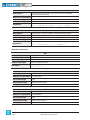
Contents
1.Overview
1.1
The workspace
1
1.1.1
The output window
2
1.1.2
The status bar
2
1.1.3
The document bar
2
1.1.4
The watch window
3
1.1.5
The library window
3
1.1.6
The workspace window
5
1.1.7
The source code editors
6
Quick start
7
2.1
Setup procedure
7
2.2
Using the IDE
8
2.3
A more complex example
13
Using the environment
15
Layout customization
15
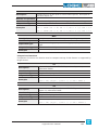
2.
3.
3.1
3.2Toolbars
15
3.2.1
Showing/hiding toolbars
15
3.2.2
Moving toolbars
15
3.3
Docking windows
17
3.3.1
Showing/hiding tool windows
17
3.3.2
Moving tool windows
18
3.4
Working with windows
19
3.4.1
The document bar
19
3.4.2
The window menu
20
3.5
Full screen mode
20
3.6
Environment options
21
Managing projects
23
4.1
Creating a new project
23
4.2
Uploading the project from the target device
23
4.3
Saving the project
25
4.3.1
Persisting changes to the project
25
4.3.2
Saving to an alternative location
25
4.4
Managing existing projects
26
4.4.1
Opening an existing LogicLab project
26
4.4.2
Editing the project
26
4.4.3
Closing the project
26
4.
1
LogicLab user manual
III
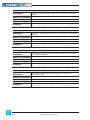
4.5
Distributing projects
26
4.6
Project options
27
4.7
Selecting the target device
28
4.8
Working with libraries
28
4.8.1
The library manager
28
4.8.2
Exporting to a library
30
4.8.3
Importing from a library or another source
31
Managing project elements
33
5.1
Program Organization Units
33
5.1.1
Creating a new Program Organization Unit
33
5.1.2
Editing POUs
34
5.1.3
Deleting POUs
35
5.1.4
Source code encryption
36
5.
5.2Variables
37
5.2.1
Global variables
37
5.2.2
Local variables
43
5.3Tasks
44
5.3.1
Assigning a program to a task
44
5.3.2
Task configuration
45
5.4
Derived data types
45
5.4.1Typedefs
45
5.4.2Structures
47
5.4.3Enumerations
49
5.4.4Subranges
50
5.5
Browsing the project
52
5.5.1
object browser
52
5.5.2
Searching with the Find in project command
61
5.6
Working with LogicLab extensions
63
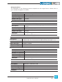
Editing the source code
65
6.1
Instruction List (IL) editor
65
6.1.1
Editing functions
65
6.1.2
Reference to PLC objects
65
6.1.3
Automatic error location
65
6.
6.1.4Bookmarks
66
6.2
Structured Text (ST) Editor
66
6.2.1
Creating and editing ST objects
66
6.2.2
Editing functions
66
6.2.3
Reference to PLC objects
67
6.2.4
Automatic error location
67
IV
LogicLab user manual
6.2.5Bookmarks
67
6.3
Ladder Diagram (LD) editor
67
6.3.1
Creating a new LD document
68
6.3.2
Adding/Removing networks
68
6.3.3
Labeling networks
68
6.3.4
Inserting contacts
69
6.3.5
Inserting coils
70
6.3.6
Inserting blocks
70
6.3.7
Editing coils and contacts properties
70
6.3.8
Editing networks
71
6.3.9
Modifying properties of blocks
71
6.3.10
Getting information on a block
71
6.3.11
Automatic error retrieval
71
6.4
Function Block Diagram (FBD) editor
72
6.4.1
Creating a new FBD document
72
6.4.2
Adding/Removing networks
72
6.4.3
Labeling networks
72
6.4.4
Inserting and connecting blocks
73
6.4.5
Editing networks
74
6.4.6
Modifying properties of blocks
74
6.4.7
Getting information on a block
74
6.4.8
Automatic error retrieval
74
6.5
Sequential Function Chart (SFC) Editor
75
6.5.1
Creating a new SFC document
75
6.5.2
Inserting a new SFC element
75
6.5.3
Connecting SFC elements
75
6.5.4
Assigning an action to a step
75
6.5.5
Specifying a constant/a variable as the condition of a transition
77
6.5.6
Assigning conditional code to a transition
77
6.5.7
Specifying the destination of a jump
79
6.5.8
Editing SFC networks
79
6.6
Variables editor
79
6.6.1
Opening a variables editor
80
6.6.2
Creating a new variable
81
6.6.3
Editing variables
81
6.6.4
Deleting variables
83
6.6.5
Sorting variables
84
6.6.6
Copying variables
85
7.Compiling
87
7.1
Compiling the project
87
7.1.1
Image file loading
87
LogicLab user manual
V
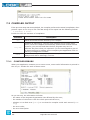
7.2
Compiler output
88
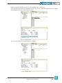
7.2.1
Compiler errors
88
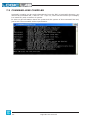
7.3
Command-line compiler
90
Launching the application
91
8.1
Setting up the communication
91
8.1.1
Saving the last used communication port
93
8.2
On-line status
93
8.2.1
Connection status
93
8.2.2
Application status
93
8.3
Downloading the application
94
8.3.1
Controlling source code download
94
8.
8.4Simulation
96
9.Debugging
97
9.1
Watch window
97
9.1.1
Opening and closing the watch window
97
9.1.2
Adding items to the watch window
98
9.1.3
Removing a variable
101
9.1.4
Refreshment of values
101
9.1.5
Changing the format of data
102
9.1.6
Working with watch lists
103
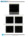
9.2Oscilloscope
104
9.2.1
Opening and closing the oscilloscope
105
9.2.2
Adding items to the oscilloscope
106
9.2.3
Removing a variable
108
9.2.4
Variables sampling
108
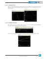
9.2.5
Controlling data acquisition and display
109
9.2.6
Changing the polling rate
115
9.2.7
Saving and printing the graph
116
9.3
Edit and debug mode
117
9.4
Live debug
118
9.4.1
SFC animation
119
9.4.2
LD animation
119
9.4.3
FBD animation
120
9.4.4
IL and ST animation
120
9.5Triggers
120
9.5.1
Trigger window
120
9.5.2
Debugging with trigger windows
126
9.6
Graphic triggers
137
9.6.1
Graphic trigger window
137
VI
LogicLab user manual
Debugging with the graphic trigger window
143
LogicLab reference
153
10.1
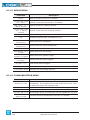
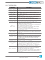
Menus reference
153
10.1.1
File menu
153
10.1.2
Edit menu
154
10.1.3
View menu
154
10.1.4
Project menu
155
10.1.5
Debug menu
156
10.1.6
Communication menu
156
10.1.7
Scheme menu
157
10.1.8
Variables menu
158
10.1.9
Definitions menu
158
10.1.10
Window menu
158
10.1.11
Help menu
158
10.2
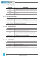
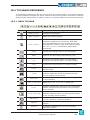
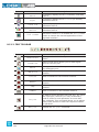
Toolbars reference
159
10.2.1
Main toolbar
159
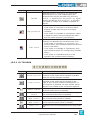
10.2.2
FBD toolbar
160
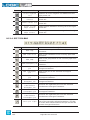
10.2.3
LD toolbar
161
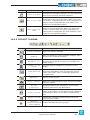
10.2.4
SFC toolbar
162
10.2.5
Project toolbar
163
10.2.6
Network toolbar
164
10.2.7
Debug toolbar
164
Language reference
165
11.1
Common elements
165
11.1.1
Basic elements
165
11.1.2
Elementary data types
165
11.1.3
Derived data types
166
9.6.2
10.
11.
11.1.4Literals
168
11.1.5Variables
169
11.1.6
Program Organization Units
172
11.1.7
IEC 61131-3 standard functions
175
11.2
Instruction List (IL)
188
11.2.1
Syntax and semantics
188
11.2.2
Standard operators
189
11.2.3
Calling Functions and Function blocks
190
11.3
Function Block Diagram (FBD)
191
11.3.1
Representation of lines and blocks
191
11.3.2
Direction of flow in networks
192
11.3.3
Evaluation of networks
192
11.3.4
Execution control elements
193
11.4
Ladder Diagram (LD)
195
LogicLab user manual
VII
11.4.1
Power rails
195
11.4.2
Link elements and states
195
11.4.3Contacts
196
11.4.4Coils
197
11.4.5
Operators, functions and function blocks
198
11.5
Structured Text (ST)
198
11.5.1Expressions
198
11.5.2
Statements in ST
199
11.6
Sequential Function Chart (SFC)
204
11.6.1Steps
204
11.6.2Transitions
206
11.6.3
Rules of evolution
207
11.7
LogicLab Language Extensions
209
11.7.1Macros
209
11.7.2Pointers
210
VIII
LogicLab user manual
1. OVERVIEW
LogicLab is an IEC61131-3 Integrated Development Environment supporting the whole
range of languages defined in the standard.
In order to support the user in all the activities involved in the development of an application, LogicLab includes:
-- textual source code editors for the Instruction List (briefly, IL) and Structured Text
(briefly, ST) programming languages (see Chapter 6.);
-- graphical source code editors for the Ladder Diagram (briefly, LD), Function Block Diagram (briefly, FBD), and Sequential Function Chart (briefly, SFC) programming languages (see Chapter 6.);
-- a compiler, which translates applications written according to the IEC standard directly
into machine code, avoiding the need for a run-time interpreter, thus making the program execution as fast as possible (see Chapter 7.);
-- a communication system which allows the download of the application to the target
environment (see Chapter 8.);
-- a rich set of debugging tools, ranging from an easy-to-use watch window to more powerful tools, which allows the sampling of fast changing data directly on the target environment, ensuring the information is accurate and reliable (see Chapter 9.).
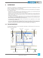
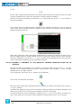
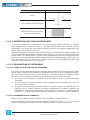
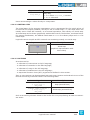
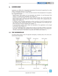
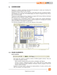
1.1 THE WORKSPACE
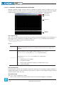
The figure below shows a view of LogicLab’s workspace, including many of its more commonly used components.
Workspace
window
Output window
Source code
editors
Document bar
Library window
LogicLab user manual
Watch window
Status bar
1
The following paragraphs give an overview of these elements.
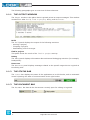
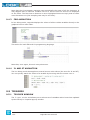
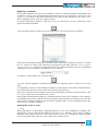
1.1.1 THE OUTPUT WINDOW
The Output window is the place where LogicLab prints its output messages. This window
contains four tabs: Build, Find in project, Debug, and Resources.
Build
The Build panel displays the output of the following activities:
-- opening a project;
-- compiling a project;
-- downloading code to a target.
Find in project
This panel shows the result of the Find in project activity.
Debug
The Debug panel displays information about advanced debugging activities (for example,
breakpoints).
Resources
The Resources panel displays messages related to the specific target device LogicLab is
interfacing with.
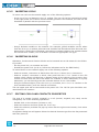
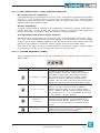
1.1.2 THE STATUS BAR
The Status bar displays the state of the application at its left border, and an animated
control reporting the state of communication at its right border.
1.1.3 THE DOCUMENT BAR
The Document bar lists all the documents currently open for editing in LogicLab.
2
LogicLab user manual
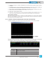
1.1.4 THE WATCH WINDOW
The Watch window is one of the many debugging tools supplied by LogicLab. Among the
other debugging tools, it is worth mentioning the Oscilloscope (see Paragraph 9.2), triggers, and the live debug mode (see Paragraph 9.4).
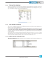
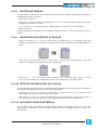
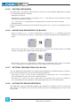
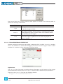
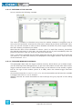
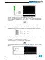
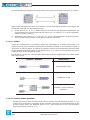
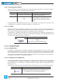
1.1.5 THE LIBRARY WINDOW
The Library window contains a set of different panels, which fall into the categories explained in the following paragraphs.
You can choose the display mode by clicking the right button of your mouse. In the View
list mode, each element is represented by its name and icon. Instead, a table appears
in the View details mode, each row of which is associated with one of the embedded
elements. The latter mode also displays the Type (Operator/Function) and the description
of each element.
If you right-click one of the elements of this panel, and you click Object properties from
the dialog box, then a window appears with further details on the element you selected
(input and output supported types, name of input and output pins, etc.).
1.1.5.1 OPERATORS AND STANDARD BLOCKS
This panel lists basic language elements, such as operators and functions defined by the
IEC 61131-3 standard.
LogicLab user manual
3
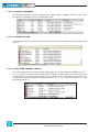
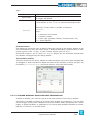
1.1.5.2 TARGET VARIABLES
This panel lists all the system variables, also called target variables, which are the interface between firmware and PLC application code.
1.1.5.3 TARGET BLOCKS
This panel lists all the system functions and function blocks available on the specific target
device.
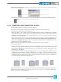
1.1.5.4 INCLUDED LIBRARY PANELS
The panels described in the preceding paragraphs are usually always available in the Library window. However, other panels may be added to this window, one for each library
included in the current LogicLab project. For example, the picture above was taken from
a LogicLab project having two included libraries, basic.pll and thermmodel.pll (see
also Paragraph 4.7).
4
LogicLab user manual
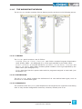
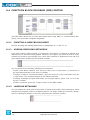
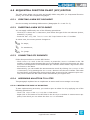
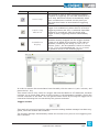
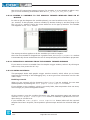
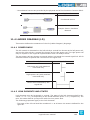
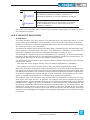
1.1.6 THE WORKSPACE WINDOW
The Workspace window consists of three distinct panels, as shown in the following picture.
1.1.6.1 PROJECT
The Project panel contains a set of folders:
-- Program, Function blocks, Functions: each folder contains Program Organization
Units (briefly, POUs - see Paragraph 5.1) of the type specified by the folder name.
-- Global variables: it is further divided in Variables, I/O Variables, Constants and
Retain variables. Each folder contains global variables of the type specified by the
folder name (see Paragraph 5.2).
-- Tasks: this item lists the system tasks and the programs assigned to each task (see
Paragraph 5.3).
1.1.6.2 DEFINITIONS
The Definitions panel contains the definitions of all user-defined data types, such as
structures or enumerated types.
1.1.6.3 RESOURCES
The contents of the Resources panel depends on the target device LogicLab is interfacing
with: it may include configuration elements, schemas, wizards, and so on.
LogicLab user manual
5
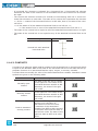
1.1.7 THE SOURCE CODE EDITORS
The LogicLab programming environment includes a set of editors to manage, edit, and
print source files written in any of the 5 programming languages defined by the IEC
61131-3 standard (see Chapter 6.).
The definition of both global and local variables is supported by specific spreadsheet-like
editors.
6
LogicLab user manual
2. QUICK START
This chapter is a step-by-step tutorial that introduces you to the use of the LogicLab development environment.
You will be guided through all the tasks you need to accomplish in order to run and monitor a simple PLC application.
The examples in this chapter refer to a virtual target, VPLC1, which is installed along with
LogicLab during the setup procedure.
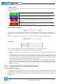
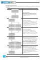
2.1 SETUP PROCEDURE
In order to install LogicLab, follow this simple procedure:
1) Close all the applications running on the system.
2) Run LogicLab’s setup executable file and follow the instructions shown in the setup
wizard.
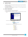
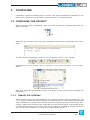
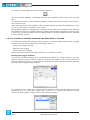
The setup procedure adds the following Start menu.
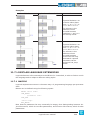
The LogicLab’s folder in the file system has the following structure.
LogicLab user manual
7
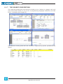
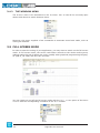
2.2 USING THE IDE
The following steps show you how to create, run and debug a simple LogicLab PLC program. The program will be written in the ST language and will be executed directly on
your machine. A virtual target, VPLC1, has been installed by the setup procedure. VPLC1
emulates a simple programmable controller provided with digital and analog I/O.
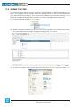
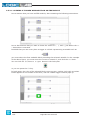
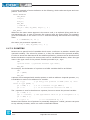
1) Launch LogicLab from the Start menu.
2) When LogicLab is started for the first time, not all windows and toolbars are shown.
You can customize LogicLab’s workspace through the View menu.
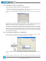
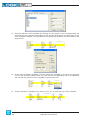
3) In order to create a new project, select the item New project from the menu File.
8
LogicLab user manual
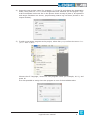
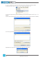
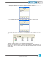
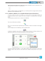
4) Insert the new project name (for example, PlcExample) and choose the destination
folder, then press OK. VPLC1 virtual target has been selected for this project. LogicLab’s workspace looks now like in the picture shown at step 2 (that is, all operators
and target variables are shown, preprocessing status log has been printed in the
output window).
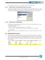
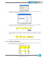
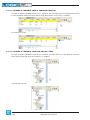
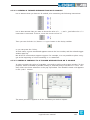
5) To add a new empty program to the project, select New program from the menu Project > New object.
Choose the ST language, insert the new program name (for example, Main), and
press OK.
It is also possible to assign here the program to one of the available tasks.
LogicLab user manual
9
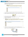
LogicLab shows now the editor window of the Main program object. On the top of the
window there is the local variables editor. The variables editor allows to add, remove,
copy and paste variable definitions.
The textual source code editor is placed in the bottom part of the window.
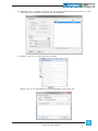
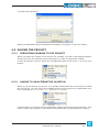
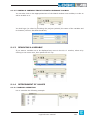
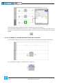
6) Insert a new local variable by pressing the Insert record button in the Project
toolbar. Alternatively, you can use the Insert option of the Variables menu.
7) Edit the name (for example, Counter) and the type of the variable. A double-click in
the type field opens the type selection dialog.
Choose the INT data type.
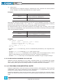
8) Implement a simple counter in ST language, as shown below.
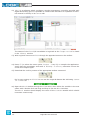
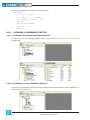
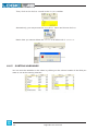
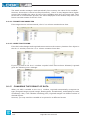
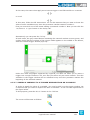
9) In order to be executed, the program Main has to be assigned to a task.
In the Workspace window, right-click on the Slow task and select the Add program
option. The Object browser window pops up.
10
LogicLab user manual
10) Select the Main program and click OK. The picture below shows the Workspace window after the successful completion of the operation.
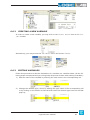
11) Select Simulation mode from Debug menu.
Name your VPLC1 workspace as PLCExampleWsp, then press OK.
LogicLab user manual
11
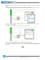
12) VPLC1 is a software which emulates a simple programmer controller provided with
digital and analog I/O. It is possible to interact with simulator as explained in SimuLab manual or briefly in Resources tab.
The status of the VPLC1 I/O is available in LogicLab as the Target variables listed
in the Library window.
13) With LogicLab connect to VPLC1 through the apposite button on the toolbar.
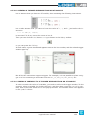
14) Press F7 (or select the menu option Project - Compile) to compile the application.
Verify that the compilation ends with 0 warning - 0 errors, otherwise correct the
errors and compile again.
15) Download the code by means of the appropriate toolbar command.
PLC is now running on VPLC1. You can see the LogicLab bottom bar indicating Source
ok - Connected.
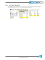
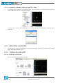
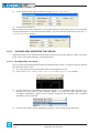
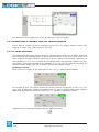
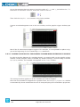
16) Open the Watch window through the View menu, then select the variable in the text
editor with a double-click and drag and drop it into the Watch window.
The Watch window should display the value of the Counter variable which should
increment continuously.
12
LogicLab user manual
You are at the end of this very simple but complete (edit-compile-download-debug) working session with LogicLab.
Further steps you should take in order to acquire a deeper knowledge of the tool include
the use of the other languages, function & function blocks, global variables, libraries, real
time debugging and so on. Refer to the following sections of this manual to obtain the
necessary information.
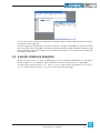
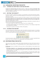
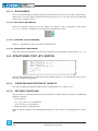
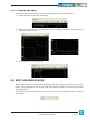
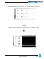
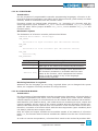
2.3 A MORE COMPLEX EXAMPLE
In the SampleProjects\Sample subdirectory of your LogicLab installation you can find a
more complex VPLC1 example, which offers an overview of IEC 61131-3 languages.
To open the project use the File - Open project menu option and open VPLC1Sample.
ppjs or select it from Example projects list in the welcome page.
LogicLab user manual
13
14
LogicLab user manual
3. USING THE ENVIRONMENT
This chapter shows you how to deal with the many UI elements LogicLab is composed of,
in order to let you set up the IDE in the way which best suits to your specific development
process.
3.1 LAYOUT CUSTOMIZATION
The layout of LogicLab’s workspace can be freely customized in order to suit your needs.
LogicLab takes care to save the layout configuration on application exit, in order to persist
your preferences between different working sessions.
3.2 TOOLBARS
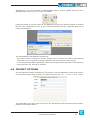
3.2.1 SHOWING/HIDING TOOLBARS
In details, in order to show (or hide) a toolbar, open the View>Toolbars menu and select
the desired toolbar (for example, the Function Block Diagram bar).
The toolbar is then shown (hidden).
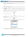
3.2.2 MOVING TOOLBARS
You can move a toolbar by clicking on its left border and then dragging and dropping it to
the destination.
The toolbar shows up in the new position.
LogicLab user manual
15
You can change the shape of the toolbar, from horizontal to vertical, either by pressing the
Shift key or by moving the toolbar next to the vertical border of any window.
You can also make the toolbar float, either by pressing the CTRL key or by moving the
toolbar away from any window border.
16
LogicLab user manual
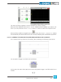
3.3 DOCKING WINDOWS
3.3.1 SHOWING/HIDING TOOL WINDOWS
The View>Tool windows menu allows you to show (or hide) a tool window (for example,
the Output window).
The tool window is then shown (hidden).
LogicLab user manual
17
3.3.2 MOVING TOOL WINDOWS
In order to move a tool window, click on its name (at the top of the window) and then drag
and drop it to the destination.
You can make the tool window float, by double-clicking on its name, or by pressing the
CTRL key, or by moving the tool window away from the main window borders.
A tool window can be resized by clicking-and-dragging on its border until the desired size
is reached.
18
LogicLab user manual
3.4 WORKING WITH WINDOWS
LogicLab allows to open many source code editors so that the workspace could get rather
messy.
You can easily navigate between these windows through the Document bar and the Window menu.
3.4.1 THE DOCUMENT BAR
The Document bar allows to switch between all the currently open editors, simply by clicking on the corresponding name.
You can show or hide the Document bar with the menu option of the same name in the
menu View>Toolbars.
LogicLab user manual
19
3.4.2 THE WINDOW MENU
The Window menu is an alternative to the Document bar: it lists all the currently open
editors and allows to switch between them.
Moreover, this menu supplies a few commands to automate some basic tasks, such as
closing all windows.
3.5 FULL SCREEN MODE
In order to ease the coding of your application, you may want to switch on the full screen
mode. In full screen mode, the source code editor extends to the whole working area,
making easier the job of editing the code, notably when graphical programming languages (that is, LD. FBD, and SFC) are involved.
You can switch on and off the full screen mode with the Full screen option of the menu
View or with the corresponding command of the Main toolbar.
20
LogicLab user manual
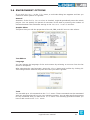
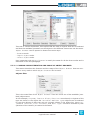
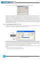
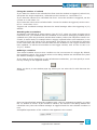
3.6 ENVIRONMENT OPTIONS
If you click Options... in the File menu, a multi-tab dialog box appears and lets you
customize some options of LogicLab.
General
Autosave: if the Enable Autosave box is checked, LogicLab periodically saves the whole
project. You can specify the period of execution of this task by entering the number of
minutes between two automatic savings in the Autosave interval text box.
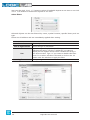
Graphic Editor
This panel lets you edit the properties of the LD, FBD, and SFC source code editors.
Text Editors
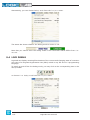
Language
You can change the language of the environment by selecting a new one from the list
shown in this panel.
After selecting the new language, press the Select button and confirm by clicking OK.
This change will be effective only the next time you start LogicLab.
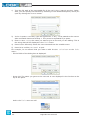
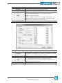
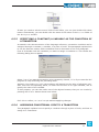
Tools
You can add up to 16 commands to the Tools menu. These commands can be associated
with any program that will run on your operating system. You can also specify arguments
for any command that you add to the Tools menu. The following procedure shows you
how to add a tool to the Tools menu.
LogicLab user manual
21
1) Type the full path of the executable file of the tool in the Command text box. Otherwise, you can specify the filename by selecting it from Windows Explorer, which you
open by clicking the Browse button.
2) In the Arguments text box, type the arguments - if any - to be passed to the executable command mentioned at step 1. They must be separated by a space.
3) Enter in Menu string the name you want to give to the tool you are adding. This is
the string that will be displayed in the Tools menu.
4) Press Add to effectively insert the new command into the suitable menu.
5) Press OK to confirm, or Cancel to quit.
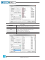
For example, let us assume that you want to add Windows calculator to the Tools
menu:
-- Fill the fields of the dialog box as displayed.
-- Press Add. The name you gave to the new tool is now displayed in the list box at the
top of the panel.
And in the Tools menu as well.
22
LogicLab user manual
4. MANAGING PROJECTS
This chapter focuses on LogicLab projects.
A project corresponds to a PLC application and includes all the required elements to run
that application on the target device, including its source code, links to libraries, information about the target device and so on.
The following paragraphs explain how to properly work with projects and their elements.
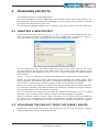
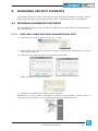
4.1 CREATING A NEW PROJECT
To start a new project, click New project in the File menu of the LogicLab main window. The same command is available in the Main toolbar and, if no project is open, in
LogicLab’s welcome page. This causes the following dialog box to appear.
You are required to enter the name of the new project in the Name control. The string
you enter will also be the name of the folder which will contain all the files making up the
LogicLab project. The pathname in the Directory control indicates the default location
of this folder.
Target selection allows you to specify the target device which will run the project.
Finally, you can make the project case-sensitive by activating the related option. Note
that, by default, this option is not active, in compliance with IEC 61131-3 standard: when
you choose to create a case-sensitive project, it will not be standard-compliant.
When you confirm your decision to create a new project and the whole required information has been provided, LogicLab completes the operation, creating the project directory
and all project files; then, the project is opened.
The list of devices from which you can select the target for the project you are creating
depends on the contents of the catalog of target devices available to LogicLab.
When the desired target is missing, either you have run the wrong setup executable or
you have to run a separate setup which is responsible to update the catalog to include
the target device. In both cases, you should contact your hardware supplier for support.
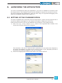
4.2 UPLOADING THE PROJECT FROM THE TARGET DEVICE
Depending on the target device you are interfacing with, you may be able to upload a
working LogicLab project from the target itself.
LogicLab user manual
23
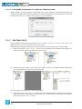
In order to upload the project from the target device, follow the procedure below:
1) Select the item Import project from target in the menu File.
2) Select the target device you are connecting to, from the list shown in the Target list
window.
3) Set up the communication (refer to Setting up the communication section for details).
4) You may optionally test the connection with the target device.
LogicLab tries to open the connection and reports the test result.
24
LogicLab user manual
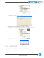
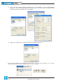
5) Confirm the operation.
When the application upload completes successfully, the project is open for editing.
4.3 SAVING THE PROJECT
4.3.1 PERSISTING CHANGES TO THE PROJECT
When you make any change to the project (for example, you add a new Program Organization Unit) you are required to save the project in order to persist that change.
To save the project, you can select the corresponding item of the menu File or the Main
toolbar.
4.3.2 SAVING TO AN ALTERNATIVE LOCATION
When you do not want to (or cannot - for example, because the file is read-only) overwrite
the project file, you may save the modified version of the project to an alternative location, by selecting Save project as... from the File menu.
LogicLab asks you to select the new destination (which must be an empty directory), then
saves a copy of the project to that location and opens this new project file for editing.
LogicLab user manual
25
4.4 MANAGING EXISTING PROJECTS
4.4.1 OPENING AN EXISTING LOGICLAB PROJECT
To open an existing project, click Open project in the File menu of LogicLab’s main
window, or in the Main toolbar, or in the Welcome page (when no project is open). This
causes a dialog box to appear, which lets you load the directory containing the project and
select the relative project file.
4.4.2 EDITING THE PROJECT
In order to modify an element of a project, you need first to open that element by doubleclicking its name, which you can find by browsing the tree structure of the project tab of
the Workspace bar.
By double-clicking the name of the object you want to modify, you open an editor consistent with the object type: for example, when you double-click the name of a project POU,
the appropriate source code editor is shown; if you double-click the name of a global variable, the variable editor is shown.
Note that LogicLab prevents you from applying changes to elements of a project, when at
least one of the following conditions holds:
-- You cannot modify any object of the project if you are in debug mode.
-- You cannot edit an object of an included library, whereas you can modify an object that
you imported from a library.
-- The project is opened in read-only mode (view project).
4.4.3 CLOSING THE PROJECT
You can terminate the working session either by explicitly closing the project or by exiting
LogicLab. In both cases, when there are changes not yet persisted to file, LogicLab asks
you to choose between saving and discarding them.
To close the project, select the item Close project from the File menu; LogicLab shows
the Welcome page, so that you can rapidly start a new working session.
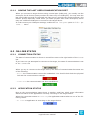
4.5 DISTRIBUTING PROJECTS
When you need to share a project with another developer you can send him/her either a
copy of the project file(s) or a redistributable source module (RSM) generated by LogicLab.
In the former case, the number of files you have to share depends on the format of the
project file:
-- PLC single project file (.ppjs file extension): the project file itself contains the whole
information needed to run the application (assuming the receiving developer has an appropriate target device available) including all source code modules, so that you need
to share only the .ppjs file.
-- PLC multiple project file (.ppjx or .ppj file extension): the project file contains only
the links to the source code modules composing the project, which are stored as single
files in the project directory. You need to share the whole directory.
26
LogicLab user manual
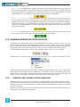
Alternatively, you can generate a redistributable source module (RSM) with the corresponding item of the Project menu or toolbar.
LogicLab notifies you of the name of the RSM file and lets you choose whether to protect
the file with a password or not. If you choose to protect the file, LogicLab asks you to
insert the password.
The advantages of the RSM file format are:
-- the source code is encoded in binary format, thus it cannot be read by third parties
which do not use LogicLab, making a transfer over the Internet more secure;
-- it can be protected with a password, which will be required by LogicLab on file opening;
-- being a binary file, its size is reduced.
4.6 PROJECT OPTIONS
You can edit some basic properties of the project, such as application name and version,
in the window which pops up after you select the item Options... in the Project menu.
The information you enter here is shown in any printed document and may also be downloaded to the target device.
LogicLab user manual
27
4.7 SELECTING THE TARGET DEVICE
You may need to port a PLC application on a target device which differs from that you
originally wrote the code for. Follow the instructions below to adapt your LogicLab project
to a new target device.
1) Click Select target in the Project menu of the LogicLab main window. This causes
the following dialog box to appear.
2) Select one of the target devices listed in the combo box.
3) Click Change to confirm your choice, Cancel to abort.
4) If you confirm, LogicLab displays the following dialog box.
Press Yes to complete the conversion, No to quit.
If you press Yes, LogicLab updates the project to work with the new target.
It also makes a backup copy of the project file(s) in a sub-directory inside the project
directory, so that you can roll-back the operation by manually (i.e., using Windows
Explorer) replacing the project file(s) with the backup copy.
4.8 WORKING WITH LIBRARIES
Libraries are a powerful tool for sharing objects between LogicLab projects. Libraries are
usually stored in dedicated source file, whose extension is .pll.
4.8.1 THE LIBRARY MANAGER
The library manager lists all the libraries currently included in a LogicLab project. It also
allows you to include or remove libraries.
28
LogicLab user manual
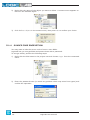
To access the library manager, click Library manager in the Project menu.
4.8.1.1 INCLUDING A LIBRARY
The following procedure shows you how to include a library in a LogicLab project, which
results in all the library’s objects becoming available to the current project.
Including a library means that a reference to the library’s .pll file is added to the current project, and that a local copy of the library is made. Note that you cannot edit the
elements of an included library, unlike imported objects.
If you want to copy or move a project which includes one or more libraries, make sure
that references to those libraries are still valid in the new location.
1) Click Library manager in the Project menu, which opens the Library manager
dialog box.
2) Press the Add button, which causes an explorer dialog box to appear, to let you select
the .pll file of the library you want to open.
3) When you have found the .pll file, open it either by double-clicking it or by pressing the Open button. The name of the library and its absolute pathname are now
displayed in a new row at the bottom of the list in the white box.
4) Repeat step 1, 2, and 3 for all the libraries you wish to include.
5) When you have finished including libraries, press either OK to confirm, or Cancel to
quit.
4.8.1.2 REMOVING A LIBRARY
The following procedure shows you how to remove an included library from the current
project. Remember that removing a library does not mean erasing the library itself, but
the project’s reference to it.
1) Click Library manager in the Project menu of the LogicLab main window, which
opens the Library manager dialog box.
LogicLab user manual
29
2) Select the library you wish to remove by clicking its name once. The Remove button
is now enabled.
3) Click the Remove button, which causes the reference to the selected library to disappear from the Project library list.
4) Repeat for all the libraries you wish to remove. Alternatively, if you want to remove
all the libraries, you can press the Remove all button.
5) When you have finished removing libraries, press either OK to confirm, or Cancel not
to apply changes.
4.8.2 EXPORTING TO A LIBRARY
You may export an object from the currently open project to a library, in order to make
that object available to other projects. The following procedure shows you how to export
objects to a library.
1) Look for the object you want to export by browsing the tree structure of the project
tab of the Workspace bar, then click once the name of the object.
2) Click Export object to library in the Project menu. This causes the following
dialog box to appear.
3) Enter the destination library by specifying the location of its .pll file. You can do
this by:
-- typing the full pathname in the white text box;
-- clicking the Browse button , in order to open an explorer dialog box which allows
you to browse your disk and the network.
4) You may optionally choose to encrypt the source code of the POU you are exporting,
in order to protect your intellectual property.
5) Click OK to confirm the operation, otherwise press Cancel to quit.
If at Step 3 of this procedure you enter the name of a non-existing .pll file, LogicLab
creates the file, thus establishing a new library.
4.8.2.1 UNDOING EXPORT TO A LIBRARY
So far, it is not possible to undo export to a library. The only possibility to remove an object is to create another library containing all the objects of the current one, except the
one you wish to delete.
30
LogicLab user manual
4.8.3 IMPORTING FROM A LIBRARY OR ANOTHER SOURCE
You can import an object from a library in order to use it in the current project. When
you import an object from a library, the local copy of the object loses its reference to the
original library and it belongs exclusively to the current project. Therefore, you can edit
imported objects, unlike objects of included libraries.
There are two ways of getting a POU from a library. The following procedure shows you
how to import objects from a library.
1) Click Import object from library in the Project menu. This causes an explorer
dialog box to appear, which lets you select the .pll file of the library you want to
open.
2) When you have found the .pll file, open it either by double-clicking it or by pressing
the Open button. The dialog box of the library explorer appears in foreground. Each
tab in the dialog box contains a list of objects of a type consistent with the tab’s title.
3) Select the tab of the type of the object(s) you want to import. You can also make
simple queries on the objects in each tab by using Filters. However, note that only
the Name filter actually applies to libraries. To use it, select a tab, then enter the name
of the desired object(s), even using the * wildcard, if necessary.
4) Select the object(s) you want to import, then press the Import object button.
5) When you have finished importing objects, press indifferently OK or Cancel to close
the Library browser.
4.8.3.1 UNDOING IMPORT FROM A LIBRARY
When you import an object in a LogicLab project, you actually make a local copy of that
object. Therefore, you just need to delete the local object in order to undo import.
LogicLab user manual
31
32
LogicLab user manual
5. MANAGING PROJECT ELEMENTS
This chapter shows you how to deal with the elements which compose a project, namely:
Program Organization Units (briefly, POUs), tasks, derived data types, and variables.
5.1 PROGRAM ORGANIZATION UNITS
This paragraph shows you how to add new POUs to the project, how to edit and eventually remove them.
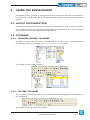
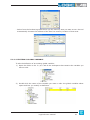
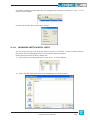
5.1.1 CREATING A NEW PROGRAM ORGANIZATION UNIT
1) Select the New object item in the Project menu.
2) Specify what kind of POU you want to create by clicking one of the items in the submenu which pops up.
3) Select the language you will use to implement the POU.
Enter the name of the new module.
4) Confirm the operation by clicking on the OK button.
Alternatively, you can create a new POU of a specific type (program, function block, or
function) by right-clicking on the correspondent item of the project tree.
LogicLab user manual
33
5.1.1.1 ASSIGNING A PROGRAM TO A TASK AT CREATION TIME
When creating a new program, LogicLab gives you the chance to assign that program to
a task at the same time: select the task you want the program to be assigned to from the
list shown in the Task section of the New program window.
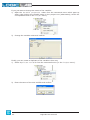
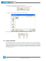
5.1.2 EDITING POUS
All the POUs of the project are listed in the Programs, Function blocks, and Functions
folders in the Project tab of the Workspace bar.
The following procedure shows you how to edit the source code of an existing POU.
1) Open the folder in the Project tab of the workspace that contains the object you
want to edit by double-clicking the folder name.
2) Double-click the name of the object you want to edit. The relative editor opens and
lets you modify the source code of the POU.
You may want to change the name of the POU:
1) Open the Object properties editor from the contextual menu which pops up when
right-clicking the POU name in the project tree (alternatively, select the correspondent item in the Project menu).
34
LogicLab user manual
2) Change the object name and confirm.
Finally, you can create a duplicate of the POU in this way:
1) Select Duplicate from the contextual menu (or the Project menu).
2) Enter the name of the new POU and confirm.
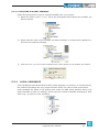
5.1.3 DELETING POUS
Follow this procedure to remove a POU from your project:
1) Open the folder in the Project tab of the workspace that contains the object you
want to delete by double-clicking the folder name.
LogicLab user manual
35
2) Right-click the name of the object you want to delete. A context menu appears referred to the selected object.
3) Click Delete object in the context menu, then press Yes to confirm your choice.
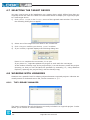
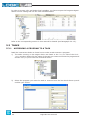
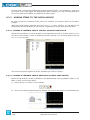
5.1.4 SOURCE CODE ENCRYPTION
You may want to hide the source code of one or more POUs.
LogicLab lets you encrypt POUs and protect them with a password.
To encrypt a POU, perform the following steps:
1) Right-click the POU name in the project tree and choose Crypt from the contextual
menu.
2) Enter the password twice (to avoid any problem which may arise from typos) and
confirm the operation.
36
LogicLab user manual
To decrypt a POU, right-click the POU name in the project tree and choose Decrypt from
the contextual menu.
LogicLab prompt you to enter the password.
You can choose to encrypt all the unencrypted POUs at once:
the same password applies to all objects.
5.2 VARIABLES
There are two classes of variables in LogicLab: global variables and local variables.
This paragraph shows you how to add to the project, edit, and eventually remove both
global and local variables.
5.2.1 GLOBAL VARIABLES
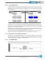
Global variables can be seen and referenced by any module of the project.
5.2.1.1 CLASSES OF GLOBAL VARIABLES
Global variables are listed in the project tree, in the Global variables folder, where they
are further classified according to their properties as Automatic variables, Mapped variables, Constants, and Retain variables.
-- Automatic variables include all the variables that the compiler automatically allocates to
an appropriate location in the target device memory.
-- Mapped variables, on the other way, do have an assigned address in the target device
logical addressing system, which shall be specified by the developer.
-- Constants list all the variables which the developer declared as having the CONSTANT
attribute, so that they cannot be written.
-- Retain variables list all the variables which the developer declared as having the RETAIN attribute, so that their values are stored in a persistent memory area of the target
device.
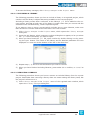
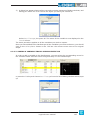
5.2.1.2 GROUPS OF GLOBAL VARIABLES
You can further categorize the set of all global variables by grouping them according to
application-specific criteria. In order to define a new group, follow this procedure:
LogicLab user manual
37
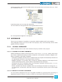
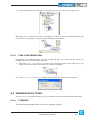
1) Select Group from the Variables menu (note that this menu is available only if the
Global variables editor is open).
2) Enter the name of the new variable group, then click Add.
3) You can now use the variable group in the declaration of new global variables.
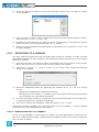
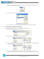
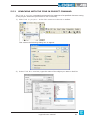
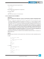
5.2.1.3 CREATING A NEW GLOBAL VARIABLE
Apply the following procedure to declare a new global variable:
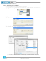
1) Select New object in the Project menu.
2) Select New variable from the menu that shows up.
3) Choose the class of the variable you want to declare (Automatic variables, Mapped
variables, Constants, or Retain variables).
4) Enter the name of the variable (remember that some characters, such as ‘?’, ‘.’, ‘/’,
and so on, cannot be used: the variable name must be a valid IEC 61131-3 identifier).
38
LogicLab user manual
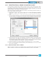
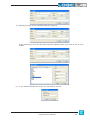
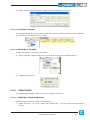
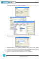
5) Specify the type of the variable either by typing it
or by selecting it from the list that LogicLab displays when you click on the Browse
button.
6) If you want to declare an array, you can specify its size.
LogicLab user manual
39
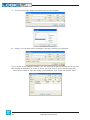
7) You may optionally assign the initial value to the variable.
8) Finally, you can add a brief description and then confirm the operation.
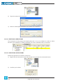
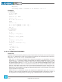
If you create a new mapped variable, you are required to specify the address of the variable during its definition. In order to do so, you may do one of the following actions:
-- Click on the button to open the editor of the address, then enter the desired value.
40
LogicLab user manual
-- Select from the list that LogicLab shows you the memory area you want to use: the tool
automatically chooses the address of the first free memory location of that area.
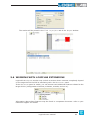
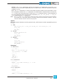
5.2.1.4 EDITING A GLOBAL VARIABLE
To edit the definition of an existing global variable:
1) Open the folder in the Project tab of the workspace that contains the variable you
want to edit.
2) Double-click the name of the variable you want to edit: the global variables editor
opens and lets you modify its definition.
LogicLab user manual
41
If you just want to change the name of the variable:
1) Open the Variable properties editor from the contextual menu which pops up
when right-clicking the variable name in the project tree (alternatively, select the
correspondent item in the Project menu).
2) Change the variable name and confirm.
Finally, you can create a duplicate of the variable in this way:
1) Select Duplicate variable from the contextual menu (or the Project menu).
2) Enter the name of the new variable and confirm.
42
LogicLab user manual
5.2.1.5 DELETING A GLOBAL VARIABLE
Follow this procedure to remove a global variable from your project:
1) Open the folder in the Project tab of the workspace that contains the variable you
want to delete.
2) Right-click the name of the variable you want to delete. A context menu appears referred to the selected variable.
3) Click Delete variable in the context menu, then press Yes to confirm you choice.
5.2.2 LOCAL VARIABLES
Local variables are declared within a POU (either program, or function, or function block),
the module itself being the only project element which can refer to and access them.
Local variables are listed in the project tree under the POU which declares them (only
when that POU is open for editing), where they are further classified according to their
class (e.g., as input or inout variables).
LogicLab user manual
43
In order to create, edit, and delete local variables, you have to open the Program Organization Unit for editing and use the local variables editor.
Refer to the corresponding section in this manual for details (see Paragraph 6.6.1.2).
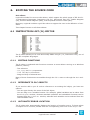
5.3 TASKS
5.3.1 ASSIGNING A PROGRAM TO A TASK
Read the instructions below to know how to make a task execute a program.
1) The tasks running on the target device are listed in the Project tab of the Workspace window. Right-click the name of the task you want to execute the program and
choose Add program from the contextual menu.
2) Select the program you want the task to execute from the list which shows up and
confirm your choice.
44
LogicLab user manual
3) The program has been assigned to the task, as you can see in the project tree.
Note that you can assign more than a program to a task. From the contextual menu you
can sort and, eventually, remove program assignments to tasks.
5.3.2 TASK CONFIGURATION
Depending on the target device you are interfacing with, you may have the chance to
configure some of the PLC tasks’ settings.
1) Select the Task configuration item in the contextual menu which pops up, if you
right-click on the name of the task you want to configure.
2) In the Task configuration window you can edit the task execution period.
5.4 DERIVED DATA TYPES
The Definitions section of the Workspace window lets you define derived data types.
5.4.1 TYPEDEFS
The following paragraphs show you how to manage typedefs.
LogicLab user manual
45
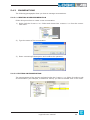
5.4.1.1 CREATING A NEW TYPEDEF
In order to define a new typedef follow this procedure:
1) Right-click the TypeDefs folder and choose New TypeDef from the contextual menu.
2) Type the name of the typedef.
3) Select the type you are defining an alias for
(if you want to define an alias for an array type, you shall choose the array size).
46
LogicLab user manual
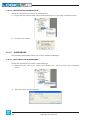
4) Enter a meaningful description (optional) and confirm the operation.
5.4.1.2 EDITING A TYPEDEF
The typedefs of the project are listed under the TypeDefs folder. In order to edit a typedef
you just have to double-click on its name.
5.4.1.3 DELETING A TYPEDEF
To delete a typedef, follow this procedure:
1) Right-click the typedef name and choose Delete from the contextual menu.
2) Confirm your choice.
5.4.2 STRUCTURES
The following paragraphs show you how to manage structures.
5.4.2.1 CREATING A NEW STRUCTURE
Follow this procedure to create a new structure:
1) Right-click the Structures folder and choose New structure from the contextual
menu.
LogicLab user manual
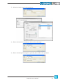
47
2) Type the name of the structure.
3) Enter a meaningful description and confirm the operation.
5.4.2.2 EDITING A STRUCTURE
The structures of the project are listed under the Structures folder. In order to edit a
structure (for example, to define its fields) you have to double-click on its name.
5.4.2.3 DELETING A STRUCTURE
Follow this procedure to delete a structure:
1) Right-click the structure name and choose Delete from the contextual menu.
2) Confirm your choice.
48
LogicLab user manual
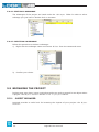
5.4.3 ENUMERATIONS
The following paragraphs show you how to manage enumerations.
5.4.3.1 CREATING A NEW ENUMERATION
Follow this procedure to create a new enumeration:
1) Right-click the Enumerations folder and choose New enumeration from the contextual menu.
2) Type the name of the enumeration.
3) Enter a meaningful description and confirm the operation.
5.4.3.2 EDITING AN ENUMERATION
The enumerations of the project are listed under the Enumerations folder. In order to edit
an enumeration (for example, to define its values) you have to double-click on its name.
LogicLab user manual
49
5.4.3.3 DELETING AN ENUMERATION
Follow this procedure to delete an enumeration:
1) Right-click the enumeration name and choose Delete from the contextual menu.
2) Confirm your choice.
5.4.4 SUBRANGES
The following paragraphs show you how to manage subranges.
5.4.4.1 CREATING A NEW SUBRANGE
Follow this procedure to create a new subrange:
1) Right-click the Subranges folder and choose New Subrange from the contextual
menu.
2) Type the name of the subrange.
50
LogicLab user manual
3) Select the basic type for the subrange.
4) Enter minimum and maximum values of the subrange.
5) Enter a meaningful description (optional) and confirm the operation.
LogicLab user manual
51
5.4.4.2 EDITING A SUBRANGE
The subranges of the project are listed under the Subranges folder. In order to edit a
subrange you just have to double-click on its name.
5.4.4.3 DELETING A SUBRANGE
Follow this procedure to delete a subrange:
1) Right-click the subrange name and choose Delete from the contextual menu.
2) Confirm your choice.
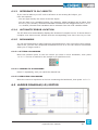
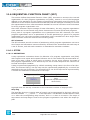
5.5 BROWSING THE PROJECT
Projects may grow huge, hence LogicLab provides two tools to search for an object within
a project: the Object browser and the Find in project feature.
5.5.1 OBJECT BROWSER
LogicLab provides a useful tool for browsing the objects of your project: the Object
browser.
52
LogicLab user manual
This tool is context dependent, this implies that the kind of objects that can be selected
and that the available operations on the objects in the different context are not the same.
Object browser can be opened in these three main ways:
-- Browser mode.
-- Import object mode.
-- Select object mode.
User interaction with Object browser is mainly the same for all the three modes and is
described in the next paragraph.
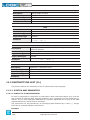
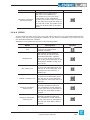
5.5.1.1 COMMON CHARACTERISTICS AND USAGE OF OBJECT BROWSER
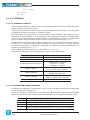
This section describes the features and the usage of the Object browser that are common to every mode in which Object browser can be used.
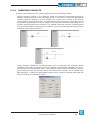
Objects filter
This is the main filter of the Object browser. User can check one of the available (enabled) object items.
In this example, Programs, Function Blocks, Functions are selected, so objects of this
type are shown in the object list. Variables and User types objects can be selected
by user but objects of that type are not currently shown in the object list. Operators,
Standard functions, Local variables, and Basic types cannot be checked by user
(because of the context) so cannot be browsed.
LogicLab user manual
53
User can also click Check all button to select all available objects at one time or can click
Check none button to deselect all objects at one time.
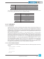
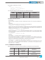
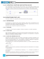
Other filters
Selected objects can be also filtered by name, symbol location, specific library and var
type.
Filters are all additive and are immediately applied after setting.
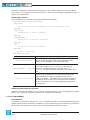
Name
Function
Set of legal values
Use
Filters objects on the base of their name.
All the strings of characters.
Type a string to display the specific object whose name
matches the string. Use the * wildcard if you want to
display all the objects whose name contains the string in
the Name text box. Type * if you want to disable this filter.
Press Enter when edit box is focused or click on the OK
button near the edit box to apply the filter.
Applies to
54
All object types.
LogicLab user manual
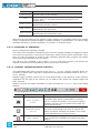
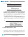
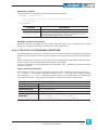
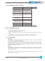
Symbol location
Function
Set of legal values
Filters objects on the base of their location.
All, Project, Target, Library, Aux. Sources.
All= Disables this filter.
Project= Objects declared in the LogicLab project.
Use
Target= Firmware objects.
Library= Objects contained in a library. In this case, use
simultaneously also the Library filter, described below.
Aux sources= Shows aux sources only.
Applies to
All objects types.
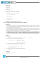
Library
Function
Set of legal values
Completes the specification of a query on objects contained
in libraries. The value of this control is relevant only if the
Symbol location filter is set to Library.
All, libraryname1, libraryname2, ...
All= Shows objects contained in whatever library.
Use
Applies to
LibrarynameN= Shows only the objects contained in the
library named librarynameN.
All objects types.
LogicLab user manual
55
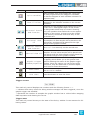
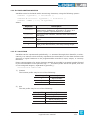
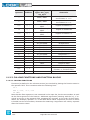
Vars Type
Function
Set of legal values
Filters global variables and system variables (also known
as firmware variables) according to their type.
All, Normal, Constant, Retain
All= Shows all the global and system variables.
Use
Normal= Shows normal global variables only.
Constant= Shows constants only.
Retain= Shows retain variables only.
Applies to
56
Variables.
LogicLab user manual
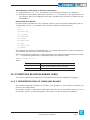
Object list
Object list shows all the filtered objects. List can be ordered in ascending or discending way by clicking on the header of the column. So it is possible to order items by Name,
Type, or Description.
Double-clicking on an item allows the user to perform the default associated operation
(the action is the same of the OK, Import object, or Open source button actions).
When item multiselection is allowed, Select all and Select none buttons are visible.
It is possible to select all objects by clicking on Select all button. Select none deselects all objects.
If at least an item is selected on the list operation, buttons are enabled.
LogicLab user manual
57
Resize
Window can be resized, the cursor changes along the border of the dialog and allows the
user to resize window. When reopened, Object browser dialog takes the same size and
position of the previous usage.
Close dialog
You have two options for closing the Object browser:
-- Press the button near the right-end border of the caption bar.
-- Press the Cancel/OK button below the filter box.
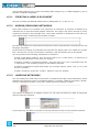
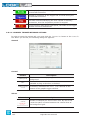
5.5.1.2 USING OBJECT BROWSER AS A BROWSER
To use Object browser in this way click on Object browser in the Project menu. This
causes the Object browser dialog box to appear, which lets you navigate between the
objects of the currently open project.
Available objects
In this mode you can list objects of these types:
-- Programs.
-- Function Blocks.
-- Functions.
-- Variables.
-- User types.
These items can be checked or unchecked in Objects filter section to show or to hide
the objects of the chosen type in the list.
Other types of objects (Operators, Standard functions, Local variables, Basic types) cannot be browsed in this context so they are unchecked and disabled).
Available operations
58
LogicLab user manual
Allowed operations in this mode are:
Open source, default operation for double-click on an item
Function
Opens the editor by which the selected object was created
and displays the relevant source code.
If the object is a program, or a function, or a function
block, this button opens the relevant source code editor.
Use
If the object is a variable, then this button opens the
variable editor.
Select the object whose editor you want to open, then click
on the Open source button.
Export to library
Function
Use
To export an object to a library.
Select the objects you want to export, then press the
Export to library button.
Delete objects
Function
Use
Allows you to delete an object.
Select the object you want to delete, then press the
Delete object button.
Multi selection
Multi selection is allowed for this mode, Select all and Select none buttons are visible.
5.5.1.3 USING OBJECT BROWSER FOR IMPORT
Object browser is also used to support objects importation in the project from a desired
external library. Select Import object from library in the Project menu, then choose
the desired library.
LogicLab user manual
59
Available objects
In this mode you can list objects of these types:
-- Programs.
-- Function blocks.
-- Functions.
-- Variables.
-- User types.
These items can be checked or unchecked in Objects filter section to show or to hide
the objects of the chosen type in the list.
Other types of objects (Operators, Standard functions, Local variables, Basic types) cannot be imported so they are unchecked and disabled.
Available operations
Import objects is the only operation supported in this mode. It is possible to import
selected objects by clicking on Import objects button or by double-clicking on one of
the objects in the list.
Multi selection
Multi selection is allowed for this mode, Select all and Select none buttons are visible.
5.5.1.4 USING OBJECT BROWSER FOR OBJECT SELECTION
Object browser dialog is useful for many operations that requires the selection of a single
PLC object. So Object browser can be used to select the program to add to a task, to select the type of a variable, to select an item to find in the project, etc..
Available objects
Available objects are strictly dependent on the context, for example in the program assignment to a task operation the only available objects are programs objects.
It is possible that not all available objects are selected by default.
Available operations
In this mode it is possible to select a single object by double-clicking on the list or by clicking on the OK button, then the dialog is automatically closed.
Multi selection
Multi selection is not allowed for this mode, Select all and Select none buttons are
not visible.
60
LogicLab user manual
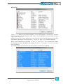
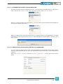
5.5.2 SEARCHING WITH THE FIND IN PROJECT COMMAND
The Find in project command retrieves all the instances of a specified character string
in the project. Follow the procedure to use it correctly.
1) Click Find in project... in the Edit menu or in the Main toolbar.
This causes the following dialog box to appear.
2) In the Find what text box, type the name of the object you want to look for.
LogicLab user manual
61
Otherwise, click the Browse button to the right of the text box, and select the name
of the object from the list of all the existing items.
3) Select one of the values listed in the Location combo box, so as to specify a constraint on the location of the objects to be inspected.
4) The frame named Filters contains 7 checkboxes, each of which, if ticked, enables
research of the string among the object it refers to.
5) Tick Match whole word only if you want to compare your string to entire word only.
6) Tick Match case if you want your search to be case-sensitive.
7) Press Find to start the search, otherwise click Cancel to abandon.
62
LogicLab user manual
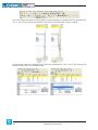
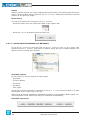
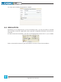
The results will be printed in the Find in project tab of the Output window.
5.6 WORKING WITH LOGICLAB EXTENSIONS
LogicLab’s Workspace window may include a section whose contents completely depend
on the target device the IDE is interfacing with: the Resources panel.
If the Resources panel is visible, you can access some additional features related to the
target device (configuration elements, schemas, wizards, and so on).
Information about these features may be found in a separate document: refer to your
hardware supplier for details.
LogicLab user manual
63
64
LogicLab user manual
6. EDITING THE SOURCE CODE
PLC editors
LogicLab includes five source code editors, which support the whole range of IEC 611313 programming languages: Instruction List (IL), Structured Text (ST), Ladder Diagram
(LD), Function Block Diagram (FBD), and Sequential Function Chart (SFC).
Moreover, LogicLab includes a grid-like editor to support the user in the definition of variables.
This chapter focuses on all these editors.
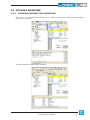
6.1 INSTRUCTION LIST (IL) EDITOR
The IL editor allows you to code and modify POUs using IL (i.e., Instruction List), one of
the IEC-compliant languages.
6.1.1 EDITING FUNCTIONS
The IL editor is endowed with functions common to most editors running on a Windows
platform, namely:
-- Text selection.
-- Cut, Copy, and Paste operations.
-- Find and Replace functions.
-- Drag-and-drop of selected text.
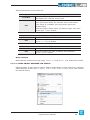
Many of these functions are accessible through the Edit menu or through the Main toolbar.
6.1.2 REFERENCE TO PLC OBJECTS
If you need to add to your IL code a reference to an existing PLC object, you have two
options:
-- You can type directly the name of the PLC object.
-- You can drag it to a suitable location. For example, global variables can be taken from
the Workspace window, whereas standard operators and embedded functions can be
dragged from the Libraries window, whereas local variables can be selected from the
local variables editor.
6.1.3 AUTOMATIC ERROR LOCATION
The IL editor also automatically displays the location of compiler errors. To know where
a compiler error occurred, double-click the corresponding error line in the Output bar.
LogicLab user manual
65
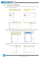
6.1.4 BOOKMARKS
You can set bookmarks to mark frequently accessed lines in your source file. Once a bookmark is set, you can use a keyboard command to move to it. You can remove a bookmark
when you no longer need it.
6.1.4.1 SETTING A BOOKMARK
Move the insertion point to the line where you want to set a bookmark, then press
Ctrl+F2. The line is marked in the margin by a light-blue circle.
6.1.4.2 JUMPING TO A BOOKMARK
Press F2 repeatedly, until you reach the desired line
6.1.4.3 REMOVING A BOOKMARK
Move the cursor to anywhere on the line containing the bookmark, then press Ctrl+ F2.
6.2 STRUCTURED TEXT (ST) EDITOR
The ST editor allows you to code and modify POUs using ST (i.e. Structured Text), one of
the IEC-compliant languages.
6.2.1 CREATING AND EDITING ST OBJECTS
See the Creating and Editing POUs section (Paragraphs 5.1.1 and 5.1.2).
6.2.2 EDITING FUNCTIONS
The ST editor is endowed with functions common to most editors running on a Windows
platform, namely:
-- Text selection.
-- Cut, Copy, and Paste operations.
-- Find and Replace functions.
-- Drag-and-drop of selected text.
Many of these functions are accessible through the Edit menu or through the Main toolbar.
66
LogicLab user manual
6.2.3 REFERENCE TO PLC OBJECTS
If you need to add to your ST code a reference to an existing PLC object, you
have two options:
-- You can type directly the name of the PLC object.
-- You can drag it to a suitable location. For example, global variables can be taken from
the Workspace window, whereas embedded functions can be dragged from the Libraries window, whereas local variables can be selected from the local variables editor.
6.2.4 AUTOMATIC ERROR LOCATION
The ST editor also automatically displays the location of compiler errors. To know where a
compiler error has occurred, double-click the corresponding error line in the Output bar.
6.2.5 BOOKMARKS
You can set bookmarks to mark frequently accessed lines in your source file. Once a bookmark is set, you can use a keyboard command to move to it. You can remove a bookmark
when you no longer need it.
6.2.5.1 SETTING A BOOKMARK
Move the insertion point to the line where you want to set a bookmark, then press
Ctrl+F2. The line is marked in the margin by a light-blue circle.
6.2.5.2 JUMPING TO A BOOKMARK
Press F2 repeatedly, until you reach the desired line.
6.2.5.3 REMOVING A BOOKMARK
Move the cursor to anywhere on the line containing the bookmark, then press Ctrl+F2.
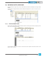
6.3 LADDER DIAGRAM (LD) EDITOR
LogicLab user manual
67
The LD editor allows you to code and modify POUs using LD (i.e. Ladder Diagram), one of
the IEC-compliant languages.
6.3.1 CREATING A NEW LD DOCUMENT
See the Creating and Editing POUs section (Paragraphs 5.1.1 and 5.1.2).
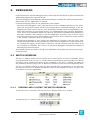
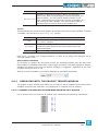
6.3.2 ADDING/REMOVING NETWORKS
Every POU coded in LD consists of a sequence of networks. A network is defined as a
maximal set of interconnected graphic elements. The upper and lower bounds of every
network are fixed by two straight lines, while each network is delimited on the left by a
grey raised button containing the network number.
On each LD network the right and the left power rail are represented, according to the LD
language indication.
On the new LD network a horizontal line links the two power rails. It is called the “power
link”. On this link, all the LD elements (contacts, coils and blocks) are to be placed.
You can perform the following operations on networks:
-- To add a new blank network, click Network>New in the Scheme menu, or press one of
the equivalent buttons in the Network toolbar.
-- To assign a label to a selected network, give the Network>Label command from the
Scheme menu. This enables jumping to the labeled network.
-- To display a background grid which helps you to align objects, press View grid in the
Network toolbar.
-- To add a comment, press the Comment button in the FBD toolbar.
6.3.3 LABELING NETWORKS
You can modify the usual order of execution of networks through a jump statement, which
transfers the program control to a labeled network. To assign a label to a network, doubleclick the raised grey button on the left, which bears the network number.
This causes a dialog box to appear, where you can type the label you want to associate
with the selected network.
If you press OK, the label is printed in the top left-hand corner of the selected network.
68
LogicLab user manual
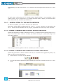
6.3.4 INSERTING CONTACTS
To insert new contacts on the network apply one of the following options:
-- Select a contact, a block or a connection. Select the insertion mode between serial or
parallel (using the button on the LD toolbar or the Scheme menu). Insert the appropriate
contact (using the button on the LD toolbar, the Scheme>Object>New or the pop-up
menu option). For serial insertion, the new contact will be inserted on the right side of
the selected contact/block or in the middle of the selected connection depending on the
element selected before the insertion. For parallel insertions, several contacts/blocks
can be selected before performing the insertion. The new contact will be inserted at the
endpoints of the selection block.
-- Drag a boolean variable to the desired place over a connection. For example, global
variables can be taken from the Workspace window, whereas local variables can be selected from the local variables editor. The dialog box shown below will appear, requesting to define whether the variable should be inserted as a contact, coil or variable (like
FBD schemes). Choose the appropriate contact type. Contacts inserted with drag and
drop will always be inserted in series.
LogicLab user manual
69
6.3.5 INSERTING COILS
To insert new coils on the network apply one of the following options:
-- Press one of the coil buttons in the LD toolbar. The new coil will be inserted and linked
to the right power rail. If other coils are already present in the network, the new coil will
be added in parallel with the previous ones.
-- Drag a boolean variable on the network. For example, global variables can be taken
from the Workspace window, whereas local variables can be selected from the local variables editor. A dialog box will appear, requesting to indicate whether the variable should
be inserted as a contact, coil or variable. Choose the appropriate coil type.
6.3.6 INSERTING BLOCKS
Operators, functions and function blocks can be inserted into an LD network in the following modes:
-- On the power link, as contacts and coils.
-- Outside the power link (to do so, follow the indications as for the FBD blocks).
To insert blocks on the network apply one of the following options:
-- Select a contact, connection or block then click Object>New in the Scheme menu.
-- Select a contact, connection or block, then press the New block button in the FBD
toolbar, which causes a dialog box to appear listing all the objects of the project, then
choose one item from the list. If the block is a constant, a return statement, or a jump
statement, you can directly press the relevant buttons in the FBD toolbar.
-- Drag the selected object (from the Workspace window, the Libraries window or the
local variables editor) over the desired connection.
The two upper pins will be connected to the power link. The EN/ENO pins should be activated before the insertion.
6.3.7 EDITING COILS AND CONTACTS PROPERTIES
The type of a contact (normal, negated) or a coil (normal, negated, set, reset) can be
changed by one of the following operations:
-- Double-click on the element (contact or coil).
-- Select the element and then press the Enter key.
-- Select the element, activate the pop-up menu with the right mouse button, then select
Properties.
An apposite dialog box will appear. Select the desired element type from the list presented
and then press OK.
70
LogicLab user manual
6.3.8 EDITING NETWORKS
The LD editor is endowed with functions common to most graphic applications running on
a Windows platform, namely:
-- Selection of a block.
-- Selection of a set of blocks by pressing Shift+Right button and by drawing a frame
including the blocks to select.
-- Cut, Copy, and Paste operations of a single block as well as of a set of blocks.
-- Drag-and-drop.
All the mentioned functions are accessible through the Edit menu or through the Main
toolbar.
6.3.9 MODIFYING PROPERTIES OF BLOCKS
-- Click Increment pins + in the Scheme menu, or press the Inc pins button in the FBD
toolbar, to increment the number of input pins of some operators and embedded functions.
-- Click Enable EN/ENO pins in the Scheme menu, or press the EN/ENO button in the FBD
toolbar, to display the enable input and output pins.
-- Click Object . Instance name in the Scheme menu, or press the FBD properties button in the FBD toolbar, to change the name of an instance of a function block.
6.3.10 GETTING INFORMATION ON A BLOCK
You can always get information on a block that you added to an LD document, by selecting
it and then performing one of the following operations:
-- Click Object>Open source in the Scheme menu, or press the View source button in the
FBD toolbar, to open the source code of a block.
-- Click Object properties in the Scheme menu, or press the FBD properties button in
the FBD toolbar, to see properties and input/output pins of the selected block.
6.3.11 AUTOMATIC ERROR RETRIEVAL
The LD editor also automatically displays the location of compiler errors. To reach the
block where a compiler error occurred, double-click the corresponding error line in the
Output bar.
LogicLab user manual
71
6.4 FUNCTION BLOCK DIAGRAM (FBD) EDITOR
The FBD editor allows you to code and modify POUs using FBD (i.e. Function Block Diagram), one of the IEC-compliant languages.
6.4.1 CREATING A NEW FBD DOCUMENT
See the Creating and editing POUs section (Paragraphs 5.1.1 and 5.1.2).
6.4.2 ADDING/REMOVING NETWORKS
Every POU coded in FBD consists of a sequence of networks. A network is defined as a
maximal set of interconnected graphic elements. The upper and lower bounds of every
network are fixed by two straight lines, while each network is delimited on the left by a
grey raised button containing the network number.
You can perform the following operations on networks:
-- To add a new blank network, click Network>New in the Scheme menu, or press one of
the equivalent buttons in the Network toolbar.
-- To assign a label to a selected network, give the Network>Label command from the
Scheme menu. This enables jumping to the labeled network.
-- To display a background grid which helps you to align objects, press View grid in the
Network toolbar.
-- To add a comment, press the Comment button in the FBD toolbar.
6.4.3 LABELING NETWORKS
You can modify the usual order of execution of networks through a jump statement, which
transfers the program control to a labeled network. To assign a label to a network, doubleclick the raised grey button on the left, that bears the network number.
72
LogicLab user manual
This causes a dialog box to appear, which lets you type the label you want to associate
with the selected network.
If you press OK, the label is printed in the top left-hand corner of the selected network.
6.4.4 INSERTING AND CONNECTING BLOCKS
This paragraph shows you how to build a network.
Add a block to the blank network, by applying one of the following options:
-- Click Object>New in the Scheme menu.
-- Press the New block button in the FBD toolbar, which causes a dialog box to appear
listing all the objects of the project, then choose one item from the list. If the block is a
constant, a return statement, or a jump statement, you can directly press the relevant
buttons in the FBD toolbar.
-- Drag the selected object to the suitable location. For example, global variables can be
taken from the Workspace window, whereas standard operators and embedded functions can be dragged from the Libraries window, whereas local variables can be selected from the local variables editor.
Repeat until you have added all the blocks that will make up the network.
Then connect blocks:
-- Click Connection mode in the Edit menu, or press the Connection button in the FBD
toolbar, or simply press the space bar of your keyboard. Click once the source pin, then
move the mouse pointer to the destination pin: the FBD editor draws a logical wire from
the former to the latter.
-- If you want to connect two blocks having a one-to-one correspondence of pins, you can
enable the autoconnection mode by clicking Autoconnect in the Scheme menu, or by
pressing the Autoconnect button in the Network toolbar. Then take the two blocks,
drag them close to each other so as to let the corresponding pins coincide. The FBD editor automatically draws the logical wires.
If you delete a block, its connections are not removed automatically, but they become invalid and they are redrawn red. Click Delete invalid connection in the Scheme menu,
or type Ctrl+B on your keyboard.
LogicLab user manual
73
6.4.5 EDITING NETWORKS
The FBD editor is endowed with functions common to most graphic applications running
on a Windows platform, namely:
-- Selection of a block.
-- Selection of a set of blocks by pressing Shift + left button and by drawing a frame
including the blocks to select.
-- Cut, Copy and Paste operations of a single block as well as of a set of blocks.
-- Drag-and-drop.
All the mentioned functions are accessible through the Edit menu or through the Main
toolbar.
6.4.6 MODIFYING PROPERTIES OF BLOCKS
-- Click Increment pins + in the Scheme menu, or press the Inc pins button in the FBD
toolbar, to increment the number of input pins of some operators and embedded functions.
-- Click Enable EN/ENO pins in the Scheme menu, or press the EN/ENO button in the FBD
toolbar, to display the enable input and output pins.
-- Click Object>Instance name in the Scheme menu, or press the FBD properties button
in the FBD toolbar, to change the name of an instance of a function block.
6.4.7 GETTING INFORMATION ON A BLOCK
You can always get information on a block that you added to an FBD document, by selecting it and then performing one of the following operations:
-- Click Object> Open source in the Scheme menu, or press the View source button in
the FBD toolbar, to open the source code of a block.
-- Click Object properties in the Scheme menu, or press the FBD properties button in
the FBD toolbar, to see properties and input/output pins of the selected block.
6.4.8 AUTOMATIC ERROR RETRIEVAL
The FBD editor also automatically displays the location of compiler errors. To reach the
block where a compiler error occurred, double-click the corresponding error line in the
Output bar.
74
LogicLab user manual
6.5 SEQUENTIAL FUNCTION CHART (SFC) EDITOR
The SFC editor allows you to code and modify POUs using SFC (i.e. Sequential Function
Chart), one of the IEC-compliant languages.
6.5.1 CREATING A NEW SFC DOCUMENT
See the creating and editing POUs section (Paragraphs 5.1.1 and 5.1.2).
6.5.2 INSERTING A NEW SFC ELEMENT
You can apply indifferently one of the following procedures:
-- Click Object>New in the Scheme menu, then select the type of the new element (action,
transition, or jump).
-- Press the New step, Add Transition or Add Jump button in the SFC toolbar.
In either case, the mouse pointer changes to:
for steps;
for transitions;
for jumps.
6.5.3 CONNECTING SFC ELEMENTS
Follow this procedure to connect SFC blocks:
-- Click Connection mode in the Edit menu, or press the Connection button in the FBD
toolbar, or simply press the space bar on your keyboard. Click once the source pin, then
move the mouse pointer to the destination pin: the SFC editor draws a logical wire from
the former to the latter.
-- Alternatively, you can enable the autoconnection mode by clicking Autoconnect in the
Scheme menu, or by pressing the Autoconnect button in the Network toolbar. Then take
the two blocks, and drag them close to each other so as to let the respective pins coincide, which makes the SFC editor draw automatically the logical wire.
6.5.4 ASSIGNING AN ACTION TO A STEP
This paragraph explains how to implement an action and how to assign it to a step.
6.5.4.1 WRITING THE CODE OF AN ACTION
To start implementing an action, you need to open an editor. Do it by applying one of the
following procedures:
-- Click Code object>New action in the Scheme menu.
-- Right-click on the name of the SFC POU in the Workspace window. A context menu appears, from which you can select the New Action command.
LogicLab user manual
75
In either case, LogicLab displays a dialog box like the one shown below.
Select one of the languages and type the name of the new action in the text box at the
bottom of the dialog box. Then either confirm by pressing OK, or quit by clicking Cancel.
If you press OK, LogicLab opens automatically the editor associated with the language you
selected in the previous dialog box and you are ready to type the code of the new action.
Note that you are not allowed to declare new local variables, as the module you are now
editing is a component of the original SFC module, which is the POU where local variables
can be declared. The scope of local variables extends to all the actions and transitions
making up the SFC diagram.
6.5.4.2 ASSIGNING AN ACTION TO A STEP
When you have finished writing the code, double-click the step you want to assign the
new action to. This causes the following dialog box to appear.
From the list shown in the Code N box, select the name of the action you want to execute
if the step is active. You may also choose, from the list shown in the Code P (Pulse) box,
the name of the action you want to execute each time the step becomes active (that is,
the action is executed only once per step activation, regardless of the number of cycles
the step remains active). Confirm the assignments by pressing OK.
In the SFC schema, action to step assignments are represented by letters on the step
block:
-- action N by letter N in the top right corner;
-- action P by letter P in the bottom right corner.
76
LogicLab user manual
If later you need to edit the source code of the action, you can just double-click these
letters. Alternatively, you can double-click the name of the action in the Actions folder of
the Workspace window.
6.5.5 SPECIFYING A CONSTANT/A VARIABLE AS THE CONDITION OF
A TRANSITION
As stated in the relevant section of the language reference, a transition condition can be
assigned through a constant, a variable, or a piece of code. This paragraph explains how
to use the first two means, while conditional code is discussed in the next paragraph.
First of all double-click the transition you want to assign a condition to. This causes the
following dialog box to appear.
Select True if you want this transition to be constantly cleared, False if you want the PLC
program to keep executing the preceding block.
Instead, if you select Variable the transition will depend on the value of a Boolean variable. Click the corresponding bullet, to make the text box to its right available, and to
specify the name of the variable.
To this purpose, you can also make use of the objects browser, that you can invoke by
pressing the Browse button shown here below.
Click OK to confirm, or Cancel to quit without applying changes.
6.5.6 ASSIGNING CONDITIONAL CODE TO A TRANSITION
This paragraph explains how to specify a condition through a piece of code, and how to
assign it to a transition.
LogicLab user manual
77
6.5.6.1 WRITING THE CODE OF A CONDITION
Start by opening an editor, following one of these procedures:
-- Click Code object>New transition in the Scheme menu.
-- Right-click on the name of the SFC POU in the Workspace window, then select the New
transition command from the context menu that appears.
In either case, LogicLab displays a dialog box similar the one shown in the following picture.
Note that you can use any language except SFC to code a condition. Select one of the
languages and type the name of the new condition in the text box at the bottom of the
dialog box. Then either confirm by pressing OK, or quit by clicking Cancel.
If you press OK, LogicLab opens automatically the editor associated with the language
you selected in the previous dialog box and you can type the code of the new condition.
Note that you are not allowed to declare new local variables, as the module you are now
editing is a component of the original SFC module, which is the POU where local variables
can be declared. The scope of local variables extends to all the actions and transitions
making up the SFC diagram.
6.5.6.2 ASSIGNING A CONDITION TO A TRANSITION
When you have finished writing the code, double-click the transition you want to assign
the new condition to. This causes the following dialog box to appear.
Select the name of the condition you want to assign to this step. Then confirm by pressing OK.
If later you need to edit the source code of the condition, you can double-click the name
78
LogicLab user manual
of the transition in the Transitions folder of the Workspace window.
6.5.7 SPECIFYING THE DESTINATION OF A JUMP
To specify the destination step of a jump, double-click the jump block in the Chart area.
This causes the dialog box shown below to appear, listing the name of all the existing
steps. Select the destination step, then either press OK to confirm or Cancel to quit.
6.5.8 EDITING SFC NETWORKS
The SFC editor is endowed with functions common to most graphic applications running
on a Windows platform, namely:
-- Selection of a block.
-- Selection of a set of blocks by pressing Ctrl + left button.
-- Cut, Copy, and Paste operations of a single block as well as of a set of blocks.
-- Drag-and-drop.
Some of these functions are accessible through the Edit menu or through the Main toolbar.
6.6 VARIABLES EDITOR
LogicLab includes a graphical editor for both global and local variables that supplies a
user-friendly interface for declaring and editing variables: the tool takes care of the translation of the contents of these editors into syntactically correct IEC 61131-3 source code.
As an example, consider the contents of the Global variables editor represented in the
following figure.
LogicLab user manual
79
The corresponding source code will look like this:
VAR_GLOBAL
gA : BOOL := TRUE;
gB : ARRAY[ 0..4 ] OF REAL;
gC AT %MD60.20 : REAL := 1.0;
END_VAR
VAR_GLOBAL CONSTANT
gD : INT := -74;
END_VAR
6.6.1 OPENING A VARIABLES EDITOR
6.6.1.1 OPENING THE GLOBAL VARIABLES EDITOR
In order to open the Global variables editor, double-click on Global variables in the
project tree.
6.6.1.2 OPENING A LOCAL VARIABLES EDITOR
To open a local variables editor, just open the Program Organization Unit the variables you
want to edit are local to.
80
LogicLab user manual
6.6.2 CREATING A NEW VARIABLE
In order to create a new variable, you may click on the Insert record item in the Project toolbar.
Alternatively, you may access the Variables menu and choose Insert.
6.6.3 EDITING VARIABLES
Follow this procedure to edit the declaration of a variable in a variables editor (all the following steps are optional and you will typically skip most of them when editing a variable):
1) Edit the name of the variable by entering the new name in the corresponding cell.
2) Change the variable type, either by editing the type name in the corresponding cell
or by clicking on the button in that cell and select the desired type from the list that
pops up.
LogicLab user manual
81
3) Edit the address of the variable by clicking on the button in the corresponding cell
and entering the required information in the window that shows up. Note that, in the
case of global variables, this operation may change the position of the variable in the
project tree.
4) In the case of global variables, you can assign the variable to a group, by selecting
it from the list which opens when you click on the corresponding cell. This operation
will change the position of the variable in the project tree.
5) Choose whether a variable is an array or not; if it is, edit the size of the variable.
82
LogicLab user manual
6) Edit the initial values of the variable: click on the button in the corresponding cell and
enter the values in the window that pops up.
7) Assign an attribute to the variable (for example, CONSTANT or RETAIN), by selecting it
from the list which opens when you click on the corresponding cell.
8) Type a description for the variable in the corresponding cell. Note that, in the case of
global variables, this operation may change the position of the variable in the project
tree.
9) Save the project to persist the changes you made to the declaration of the variable.
6.6.4 DELETING VARIABLES
In order to delete one or more variables, select them in the editor: you may use the CTRL
or the SHIFT keys to select multiple elements.
LogicLab user manual
83
Then, click on the Delete record in the Project toolbar.
Alternatively, you may access the Variables menu and choose Delete.
Notice that you cannot delete the RESULT of an IEC61131-3 FUNCTION.
6.6.5 SORTING VARIABLES
You can sort the variables in the editor by clicking on the column header of the field you
want to use as the sorting criterion.
84
LogicLab user manual
6.6.6 COPYING VARIABLES
The variables editor allows you to quickly copy and paste elements. You can either use
keyboard shortcuts or the Edit menu to access these features.
LogicLab user manual
85
86
LogicLab user manual
7. COMPILING
Compilation consists of taking the PLC source code and automatically translating it into
binary code, which can be executed by the processor on the target device.
7.1 COMPILING THE PROJECT
Before starting actual compilation, make sure that at least one program has been assigned to a task.
When this pre-condition does not hold, compilation aborts with a meaningful error message.
In order to start compilation, click the Compile button in the Project toolbar.
Alternatively, you can choose Compile from the Project menu or press F7 on your keyboard.
Note that LogicLab automatically saves all changes to the project before starting the
compilation.
7.1.1 IMAGE FILE LOADING
Before performing the actual compilation, the compiler needs to load the image file (img
file), which contains the map of memory of the target device. If the target is connected
when compilation is started, the compiler seeks the image file directly on the target. Otherwise, it loads the local copy of the image file from the working folder. If the target device
is disconnected and there is no local copy of the image file, compilation cannot be carried
out: you are then required to connect to a working target device.
LogicLab user manual
87
7.2 COMPILER OUTPUT
If the previous step was accomplished, the compiler performs the actual compilation, then
prints a report in the Output bar. The last string of the report has the following format:
m warnings, n errors
It tells the user the outcome of compilation.
Condition
Description
n>0
Compiler error(s). The PLC code contains one or more serious errors,
which cannot be worked around by the compiler.
n=0, m>0
Emission of warning(s). The PLC code contains one or more minor
errors, which the compiler automatically spotted and worked around.
However, you are informed that the PLC program may act in a
different way from what you expected: you are encouraged to get rid
of these warnings by editing and re-compiling the application until no
warning messages are emitted.
n=m=0
PLC code entirely correct, compilation accomplished. You should
always work with 0 warnings, 0 errors.
7.2.1 COMPILER ERRORS
When your application contains one or more errors, some useful information is printed in
the Output window for each of those errors.
As you can see, the information includes:
-- the name of the Program Organization Unit affected by the error;
-- the number of the source code line which procured the error;
-- whether it is a fatal error (error) or one that the compiler could work around (warning);
-- the error code;
-- the error description.
88
LogicLab user manual
Refer to the appropriate section for the compiler error reference.
If you double-click the error message in the Output bar, LogicLab opens the source code
and highlights the line containing the error.
You can then solve the problem and re-compile.
LogicLab user manual
89
7.3 COMMAND-LINE COMPILER
LogicLab’s compiler can be used independently from the IDE: in LogicLab’s directory, you
can find an executable file, Command-line compiler, which can be invoked (for example,
in a batch file) with a number of options.
In order to get information about the syntax and the options of this command-line tool,
just launch the executable without parameters.
90
LogicLab user manual
8. LAUNCHING THE APPLICATION
In order to download and debug the application, you have to establish a connection with
the target device. This chapter focuses on the operations required to connect to the target and to download the application, while the wide range of LogicLab’s debugging tools
deserves a separate chapter (see Chapter 9.).
8.1 SETTING UP THE COMMUNICATION
In order to establish the connection with the target device, make sure the physical link is
up (all the cables are plugged in, the network is properly configured, and so on).
Follow this procedure to set up and establish the connection to the target device:
1) Click Settings in the Communication menu of the LogicLab main window. This
causes the following dialog box to appear.
The elements in the list of communication protocols you can select from depend on
the setup executable(s) you have run on your PC (refer to your hardware provider if
a protocol you expect to appear in the list is missing).
2) Choose the appropriate protocol and make it the active protocol.
LogicLab user manual
91
3) Fill in all the protocol-specific settings (e.g., the address or the communication
timeout - that is how long LogicLab must wait for an answer from the target before
displaying a communication error message).
4) Apply the changes you made to the communication settings.
Now you can establish communication by clicking Connect in the Communication menu,
or by pressing the Connect button in the Project toolbar.
92
LogicLab user manual
8.1.1 SAVING THE LAST USED COMMUNICATION PORT
When you connect to target devices using a serial port (COM port), you usually use the
same port for all devices (many modern PCs have only one COM port). You may save the
last used COM port and let LogicLab use that port to override the project settings: this
feature proves especially useful when you share projects with other developers, which
may use a different COM port to connect to the target device.
In order to save your COM port settings, enable the Use last port option in File > Options... menu.
8.2 ON-LINE STATUS
8.2.1 CONNECTION STATUS
The state of communication is shown in a small box next to the right border of the Status
bar.
If you have not yet attempted to connect to the target, the state of communication is set
to Not connected.
When you try to connect to the target device, the state of communication becomes one
of the following:
-- Error: the communication cannot be established. You should check both the physical
link and the communication settings.
-- Connected: the communication has been established.
8.2.2 APPLICATION STATUS
Next to the communication status there is another small box which gives information
about the status of the application currently executing on the target device.
When the connection status is Connected, the application status takes on one of the following values.
-- No code: no application is executing on the target device.
LogicLab user manual
93
-- Diff. code: the application currently executing on the target device is not the same as
the one currently open in the IDE; moreover, no debug information consistent with the
running application is available: thus, the values shown in the watch window or in the
oscilloscope are not reliable and the debug mode cannot be activated.
-- Diff. code, Symbols OK: the application currently executing on the target device is
not the same as the one currently open in the IDE; however, some debug information
consistent with the running application is available (for example, because that application has been previously downloaded to the target device from the same PC): the values
shown in the watch window or in the oscilloscope are reliable, but the debug mode still
cannot be activated.
-- Source OK: the application currently executing on the target device is the same as the
one currently open in the IDE: the debug mode can be activated.
8.3 DOWNLOADING THE APPLICATION
A compiled PLC application must be downloaded to the target device in order to have
the processor execute it. This paragraph shows you how to send a PLC code to a target
device. Note that LogicLab can download the code to the target device only if the latter is
connected to the PC where LogicLab is running. See the related section for details.
To download the application, click on the related button in the Project toolbar.
Alternatively, you can choose Download code from the Project menu or press the F5 key.
LogicLab checks whether the project has unsaved changes. If this is the case, it automatically starts the compilation of the application. The binary code is eventually sent to the
target device, which then undergoes automatic reset at the end of transmission. Now the
code you sent is actually executed by the processor on the target device.
8.3.1 CONTROLLING SOURCE CODE DOWNLOAD
Whether the source code of the application is downloaded along with the binary code or
not, depends on the target device you are interfacing with: some devices host the application source code in their storage, in order to allow the developer to upload the project
in a later moment.
If this is the case, you can control some aspects of the source code download process, as
explained in the following paragraphs.
94
LogicLab user manual
8.3.1.1 SUSPENDING SOURCE CODE DOWNLOAD
In order to speed up the development cycle, you may want to disable source code download: uncheck the Source code download item in the Communication menu.
When you stop developing the application, you can enable source code download again by
checking the same menu item.
When you disconnect from the target device, LogicLab checks if the application currently
executing on the target and the source code available on-board match, alerting you if
they do not.
8.3.1.2 PROTECTING THE SOURCE CODE WITH A PASSWORD
You may want to protect the source code downloaded to the target device with a password, so that LogicLab will not open the uploaded project unless the correct password is
entered.
Open the Project options window (Project > Options ... menu) and set the password.
LogicLab user manual
95
You may opt to disable the password, instead.
8.4 SIMULATION
Depending on the target device you are interfacing with, you may be able to simulate
the execution of the PLC application with LogicLab’s integrated simulation environment:
SimuLab.
In order to start the simulation, just click on the appropriate item on the Project toolbar.
Refer to SimuLab’s manual to gain information on how to control the simulation.
96
LogicLab user manual
9. DEBUGGING
LogicLab provides several debugging tools, which help the developer to check whether the
application behaves as expected or not.
All these debugging tools basically allow the developer to watch the value of selected variables while the PLC application is running.
LogicLab debugging tools can be gathered in two classes:
-- Asynchronous debuggers. They read the values of the variables selected by the developer with successive queries issued to the target device. Both the manager of the debugging tool (that runs on the PC) and, potentially, the task which is responsible to answer those queries (on the target device) run independently from the PLC application.
Thus, there is no guarantee about the values of two distinct variables being sampled in
the same moment, with respect to the PLC application execution (one or more cycles
may have occurred); for the same reason, the evolution of the value of a single variable
is not reliable, especially when it changes fast.
-- Synchronous debuggers. They require the definition of a trigger in the PLC code. They
refresh simultaneously all the variables they have been assigned every time the processor reaches the trigger, as no further instruction can be executed until the value of all
the variables is refreshed. As a result, synchronous debuggers obviate the limitations
affecting asynchronous ones.
This chapter shows you how to debug your application using both asynchronous and synchronous tools.
9.1 WATCH WINDOW
The Watch window allows you to monitor the current values of a set of variables. Being
an asynchronous tool, the Watch window does not guarantee synchronization of values.
Therefore, when reading the values of the variables in the Watch window, be aware of
the possibility that they may refer to different execution cycles of the corresponding task.
The Watch window contains an item for each variable that you added to it. The information shown in the Watch window includes the name of the variable, its value, its type, and
its location in the PLC application.
9.1.1 OPENING AND CLOSING THE WATCH WINDOW
To open the Watch window, click on the Watch button of the Main toolbar.
To close the Watch window, click on the Watch button again.
LogicLab user manual
97
Alternatively, you can click on the Close button in the top right corner of the Watch window.
In both cases, closing the Watch window means simply hiding it, not resetting it. As a
matter of fact, if you close the Watch window and then open it again, you will see that it
still contains all the variables you added to it.
9.1.2 ADDING ITEMS TO THE WATCH WINDOW
To watch a variable, you need to add it to the watch list.
Note that, unlike trigger windows and the Graphic trigger window, you can add to the
Watch window all the variables of the project, regardless of where they were declared.
9.1.2.1 ADDING A VARIABLE FROM A TEXTUAL SOURCE CODE EDITOR
Follow this procedure to add a variable to the Watch window from a textual (that is, IL or
ST) source code editor: select a variable, by double-clicking on it, and then drag it into
the watch window.
The same procedure applies to all the variables you wish to inspect.
9.1.2.2 ADDING A VARIABLE FROM A GRAPHICAL SOURCE CODE EDITOR
Follow this procedure to add a variable to the Watch window from a graphical (that is, LD,
FBD, or SFC) source code editor:
1) Press the Watch button in the FBD bar.
2) Click on the block representing the variable you wish to be shown in the Watch window.
98
LogicLab user manual
3) A dialog box appears listing all the currently existing instances of debug windows, and
asking you which one is to receive the object you have just clicked on.
In order to display the variable in the Watch window, select Watch, then press OK.
The variable name, value, and location are now displayed in a new row of the Watch window.
The same procedure applies to all the variables you wish to inspect.
Once you have added to the Watch window all the variables you want to observe, you
should click on the Select/Move button in the FBD bar: the mouse cursor turns to its
original shape.
LogicLab user manual
99
9.1.2.3 ADDING A VARIABLE FROM A VARIABLES EDITOR
In order to add a variable to the Watch window, you can select the corresponding record
in the variables editor and then either drag-and-drop it in the Watch window
or press the F8 key.
9.1.2.4 ADDING A VARIABLE FROM THE PROJECT TREE
In order to add a variable to the Watch window, you can select it in the project tree and
then either drag-and-drop it in the Watch window
or press the F8 key.
100
LogicLab user manual
9.1.2.5 ADDING A VARIABLE FROM THE WATCH WINDOW TOOLBAR
You can also click on the appropriate item of the Watch window inner toolbar, in order to
add a variable to it.
You shall type (or select by browsing the project symbols) the name of the variable and
its location (where it has been declared).
9.1.3 REMOVING A VARIABLE
If you want a variable not to be displayed any more in the Watch window, select it by
clicking on its name once, then press the Del key.
9.1.4 REFRESHMENT OF VALUES
9.1.4.1 NORMAL OPERATION
Let us consider the following example.
LogicLab user manual
101
The watch window manager reads periodically from memory the value of the variables.
However, this action is carried out asynchronously , that is it may happen that a higherpriority task modifies the value of some of the variables while they are being read. Thus,
at the end of a refreshment process, the values displayed in the window may refer to different execution states of the PLC code.
9.1.4.2 TARGET DISCONNECTED
If the target device is disconnected, the Value column contains three dots.
9.1.4.3 OBJECT NOT FOUND
If the PLC code changes and LogicLab cannot retrieve the memory location of an object in
the Watch window, then the Value column contains three dots.
If you try to add to the Watch window a symbol which has not been allocated, LogicLab
gives the following error message.
9.1.5 CHANGING THE FORMAT OF DATA
When you add a variable to the Watch window, LogicLab automatically recognizes its
type (unsigned integer, signed integer, floating point, hexadecimal), and displays its value
consistently. Also, if the variable is floating point, LogicLab assigns it a default number of
decimal figures.
However, you may need the variable to be printed in a different format.
102
LogicLab user manual
To impose another format than the one assigned by LogicLab, press the Format value
button in the toolbar.
Choose the format and confirm your choice.
9.1.6 WORKING WITH WATCH LISTS
You can store to file the set of all the items in the Watch window, in order to easily restore
the status of this debugging tools in a successive working session.
Follow this procedure to save a watch list:
1) Click on the corresponding item in the Watch window toolbar.
2) Enter the file name and choose its destination in the file system.
LogicLab user manual
103
In order to load a watch list, follow this procedure:
1) Click on the corresponding item in the Watch window toolbar.
2) Browse the file system and select the watch list file.
The set of symbols in the watch list is added to the Watch window.
9.2 OSCILLOSCOPE
The Oscilloscope allows you to plot the evolution of the values of a set of variables. Being an asynchronous tool, the Oscilloscope cannot guarantee synchronization of samples.
Opening the Oscilloscope causes a new window to appear next to the right-hand border
of the LogicLab frame. This is the interface for accessing the debugging functions that the
Oscilloscope makes available. The Oscilloscope consists of three elements, as shown in
the following picture.
104
LogicLab user manual
The toolbar allows you to better control the Oscilloscope. A detailed description of the
function of each control is given later in this chapter.
The Chart area includes several items:
-- Plot: area containing the curve of the variables.
-- Vertical cursors: cursors identifying two distinct vertical lines. The values of each variable at the intersection with these lines are reported in the corresponding columns.
-- Scroll bar: if the scale of the x-axis is too large to display all the samples in the Plot
area, the scroll bar allows you to slide back and forth along the horizontal axis.
The lower section of the Oscilloscope is a table consisting of a row for each variable.
9.2.1 OPENING AND CLOSING THE OSCILLOSCOPE
To open the Oscilloscope, click on the Async button of the Main toolbar.
To close the Oscilloscope, click on the Async button again.
Alternatively, you can click on the Close button in the top right corner of the Oscilloscope window.
LogicLab user manual
105
In both cases, closing the Oscilloscope means simply hiding it, not resetting it. As a matter of fact, if you open again the Oscilloscope after closing it, you will see that plotting of
the curve of all the variables you added to it starts again.
9.2.2 ADDING ITEMS TO THE OSCILLOSCOPE
In order to plot the evolution of the value of a variable, you need to add it to the Oscilloscope.
Note that unlike trigger windows and the Graphic trigger window, you can add to the
Oscilloscope all the variables of the project, regardless of where they were declared.
9.2.2.1 ADDING A VARIABLE FROM A TEXTUAL SOURCE CODE EDITOR
Follow this procedure to add a variable to the Oscilloscope from a textual (that is, IL or
ST) source code editor: select a variable by double-clicking on it, and then drag it into the
Oscilloscope window.
The same procedure applies to all the variables you wish to inspect.
9.2.2.2 ADDING A VARIABLE FROM A GRAPHICAL SOURCE CODE EDITOR
Follow this procedure to add a variable to the Oscilloscope from a graphical (that is, LD,
FBD, or SFC) source code editor:
1) Press the Watch button in the FBD bar.
2) Click on the block representing the variable you wish to be shown in the Oscilloscope.
106
LogicLab user manual
3) A dialog box appears listing all the currently existing instances of debug windows, and
asking you which one is to receive the object you have just clicked on.
Select Oscilloscope, the press OK. The name of the variable is now displayed in the
Track column.
The same procedure applies to all the variables you wish to inspect.
Once you have added to the Oscilloscope all the variables you want to observe, you should
click on the Select/Move button in the FBD bar: the mouse cursor turns to its original
shape.
9.2.2.3 ADDING A VARIABLE FROM A VARIABLES EDITOR
In order to add a variable to the Oscilloscope, you can select the corresponding record in
the variables editor and then either drag-and-drop it in the Oscilloscope
or press the F10 key and choose Oscilloscope from the list of debug windows which pops
up.
LogicLab user manual
107
9.2.2.4 ADDING A VARIABLE FROM THE PROJECT TREE
In order to add a variable to the Oscilloscope, you can select it in the project tree and then
either drag-and-drop it in the Oscilloscope
or press the F10 key and choose Oscilloscope from the list of debug windows which
pops up.
9.2.3 REMOVING A VARIABLE
If you want to remove a variable from the Oscilloscope, select it by clicking on its name
once, then press the Del key.
9.2.4 VARIABLES SAMPLING
9.2.4.1 NORMAL OPERATION
Let us consider the following example.
108
LogicLab user manual
The Oscilloscope manager periodically reads from memory the value of the variables.
However, this action is carried out asynchronously, that is it may happen that a higherpriority task modifies the value of some of the variables while they are being read. Thus,
at the end of a sampling process, data associated with the same value of the x-axis may
actually refer to different execution states of the PLC code.
9.2.4.2 TARGET DISCONNECTED
If the target device is disconnected, the curves of the dragged-in variables get frozen,
until communication is restored.
9.2.5 CONTROLLING DATA ACQUISITION AND DISPLAY
The Oscilloscope includes a toolbar with several commands, which can be used to control
the acquisition process and the way data are displayed. This paragraph focuses on these
commands.
Note that all the commands in the toolbar are disabled if no variable has been added to
the Oscilloscope.
9.2.5.1 STARTING AND STOPPING DATA ACQUISITION
When you add a variable to the Oscilloscope, data acquisition begins immediately.
However, you can suspend the acquisition by clicking on Pause acquisition.
LogicLab user manual
109
The curve freezes (while the process of data acquisition is still running in background),
until you click on Restart acquisition.
In order to stop the acquisition you may click on Stop acquisition.
In this case, when you click on Restart acquisition, the evolution of the value of the
variable is plotted from scratch.
9.2.5.2 SETTING THE SCALE OF THE AXES
When you open the Oscilloscope, LogicLab applies a default scale to the axes. However, if
you want to set a different scale, you may follow this procedure:
1) Open the graph properties by clicking on the corresponding item in the toolbar.
110
LogicLab user manual
2) Set the scale of the horizontal axis, which is common to all the tracks.
3) For each variable, you may specify a distinct scale for the vertical axis.
4) Confirm your settings. The graph adapts to reflect the new scale.
LogicLab user manual
111
You can also zoom in and out with respect to both the horizontal and the vertical axes.
Finally, you may also quickly adapt the scale of the horizontal axis, the vertical axis, or
both to include all the samples, by clicking on the corresponding item of the toolbar.
112
LogicLab user manual
9.2.5.3 VERTICAL SPLIT
When you are watching the evolution of two or more variables, you may want to split the
respective tracks. For this purpose, click on the Vertical split item in the Oscilloscope toolbar.
9.2.5.4 VIEWING SAMPLES
If you click on the Show samples item in the Oscilloscope toolbar, the tool highlights
the single values detected during data acquisition.
You can click on the same item again, in order to go back to the default view mode.
LogicLab user manual
113
9.2.5.5 TAKING MEASURES
The Oscilloscope includes two measure bars, which can be exploited to take some measures on the chart; in order to show and hide them, click on the Show measure bars item
in the Oscilloscope toolbar.
If you want to measure a time interval between two events, you just have to move one
bar to the point in the graph that corresponds to the first event and the other to the point
that corresponds to the second one.
The time interval between the two bars is shown in the top left corner of the chart.
You can use a measure bar also to read the value of all the variables in the Oscilloscope
at a particular moment: move the bar to the point in the graph which corresponds to the
instant you want to observe.
114
LogicLab user manual
In the table below the chart, you can now read the values of all the variables at that particular moment.
9.2.5.6 OSCILLOSCOPE SETTINGS
You can further customize the appearance of the Oscilloscope by clicking on the Graph
properties item in the toolbar.
In the window that pops up you can choose whether to display or not the Background
grid, the Time slide bar, and the Track list.
9.2.6 CHANGING THE POLLING RATE
LogicLab periodically sends queries to the target device, in order to read the data to be
plotted in the Oscilloscope.
The polling rate can be configured by following this procedure:
1) Click on the Graph properties item in the toolbar.
LogicLab user manual
115
2) In the window that pops up edit the Sampling polling rate.
3) Confirm your decision.
Note that the actual rate depends on the performance of the target device (in particular,
on the performance of its communication task). You can read the actual rate in the Oscilloscope settings window.
9.2.7 SAVING AND PRINTING THE GRAPH
LogicLab allows you to persist the acquisition either by saving the data to a file or by printing a view of the data plotted in the Oscilloscope.
9.2.7.1 SAVING DATA TO A FILE
You can save the samples acquired by the Oscilloscope to a file, in order to further analyze
the data with other tools.
1) You may want to stop acquisition before saving data to a file.
2) Click on the Save tracks data into file in the Oscilloscope toolbar.
3) Choose between the available output file format: OSC is a simple plain-text file, containing time and value of each sample; OSCX is an XML file, that includes more
complete information, which can be further analyzed with another tool, provided
separately from LogicLab.
4) Choose a file name and a destination directory, then confirm the operation.
116
LogicLab user manual
9.2.7.2 PRINTING THE GRAPH
Follow this procedure to print a view of the data plotted in the Oscilloscope:
1) Either suspend or stop the acquisition.
2) Move the time slide bar and adjust the zoom, in order to include in the view the elements you want to print.
3) Click on the Print graph item.
9.3 EDIT AND DEBUG MODE
While both the Watch window and the Oscilloscope do not make use of the source code,
all the other debuggers do: thus, LogicLab requires the developer to switch on the debug
mode, where changes to the source code are inhibited, before (s)he can access those
debugging tools.
To switch on and off the debug mode, you can click on the corresponding item in the Debug toolbar.
LogicLab user manual
117
Alternatively, you can choose Debug mode from the Project menu.
The status bar shows whether the debug mode is active or not.
Note that you cannot enter the debug mode if the connection status differs from Connected.
9.4 LIVE DEBUG
LogicLab can display meaningful animation of the current and changing state of execution
over time of a Program Organization Unit (POU) coded in any IEC 61131-3 programming
language.
To switch on and off the live debug mode, you may click on the corresponding item in the
Debug toolbar
or choose Live debug mode from the Project menu.
118
LogicLab user manual
9.4.1 SFC ANIMATION
As explained in the relevant section of the language reference, an SFC POU is structured
in a set of steps, each of which is either active or inactive at any given moment. Once
started up, this SFC-specific debugging tool animates the SFC documents by highlighting
the active steps.
Animation OFF
Animation ON
In the left column, a portion of an SFC network is shown, diagram animation being off.
In the right column the same portion of network is displayed when the live debug mode
is active. The picture in the right column shows that steps S1 and S3 are currently active,
whereas Init, S2, and S4 are inactive.
Note that the SFC animation manager tests periodically the state of all steps, the user not
being allowed to edit the sampling period. Therefore, it may happen that a step remains
active for a slot of time too short to be displayed on the video.
The fact that a step is never highlighted does not imply that its action is not executed, it
may simply mean that the sampling rate is too slow to detect the execution.
9.4.1.1 DEBUGGING ACTIONS AND CONDITIONS
As explained in the SFC language reference, a step can be assigned to an action, and a
transition can be associated with a condition code. Actions and conditions can be coded in
any of the IEC 61131-3 languages. General-purpose debugging tools can be used within
each action/condition, as if it was a stand-alone POU.
9.4.2 LD ANIMATION
In live debug mode, Ladder Diagram schemes are animated by highlighting the contacts
and coils whose value is true (in the example, i1 and i2).
LogicLab user manual
119
Note that the LD animation manager tests periodically the state of all the elements. It
may happen that an element remains true for a slot of time too short to be displayed
on the video. The fact that an element is never highlighted does not imply that its value
never becomes true (the sampling rate may be too slow).
9.4.3 FBD ANIMATION
In live debug mode, LogicLab displays the values of all the visible variables directly in the
graphical source code editor.
This works for both FBD and LD programming language.
Note that, once again, this tool is asynchronous.
9.4.4 IL AND ST ANIMATION
The live debug mode also applies to textual source code editors (the ones for IL and ST).
You can quickly watch the values of a variable by hovering with the mouse over it.
9.5 TRIGGERS
9.5.1 TRIGGER WINDOW
The Trigger window tool allows you to select a set of variables and to have them updated
synchronously in a special pop-up window.
120
LogicLab user manual
9.5.1.1 PRE-CONDITIONS TO OPEN A TRIGGER WINDOW
No need for special compilation
LogicLab debugging tools operate at run-time. Thus, unlike other programming languages
such as C++, the compiler does not need to be told whether or not to support trigger
windows: given a PLC code, the compiler’s output is unique, and there is no distinction
between debug and release version.
Memory availability
A trigger window takes a segment in the application code sector, having a well-defined
length. Obviously, in order to start up a trigger window, it is necessary that a sufficient
amount of memory is available, otherwise an error message appears.
Incompatibility with graphic trigger windows
A graphic trigger window takes the whole free space of the application code sector. Therefore, once such a debugging tool has been started, it is not possible to add any trigger
window, and an error message appears if you attempt to start a new window. Once the
graphic trigger window is eventually closed, trigger windows are enabled again.
Note that all the trigger windows existing before the starting of a graphic trigger window
keep working normally. You are simply not allowed to add new ones.
9.5.1.2 TRIGGER WINDOW TOOLBAR
Trigger window icons are part of the Debug toolbar and are enabled only if LogicLab is in
debug mode.
Button
Command
Description
In order to actually start a trigger window,
select the point of the PLC code where to insert
the relative trigger and then press this button.
Set/Remove trigger The same procedure applies to trigger window
removal: in order to definitely close a debug
window, click once the instruction/block where the
trigger was inserted, then press this button again.
Graphic trace
Pressing this key causes all the existing trigger
windows and the graphic trigger window to be
removed simultaneously. Shortcut key: pressing
Ctrl+Shift+F9 is equivalent to clicking on this
button.
Remove all
triggers
Trigger list
This button operates exactly as the above Set/
Remove trigger, except for that it opens a
graphic trigger window. It can be used likewise
also to remove a graphic trigger window. Shortcut
key: pressing Shift + F9 is equivalent to clicking
on Set/Remove trigger button.
This key opens a dialog listing all the existing
trigger windows. Shortcut key: pressing Ctrl+I is
equivalent to clicking on this button.
LogicLab user manual
121
Each record refers to a trigger window, either graphic or textual. The following table explains the meaning of each field.
Field
Type
Module
Line
Description
T: trigger window.
G: graphic trigger window.
Name of the program, function, or function block where
the trigger is placed. If the module is a function block, this
field contains its name, not the name of its instance where
you actually put the trigger.
For the textual languages (IL, ST) indicates the line in
which the trigger is placed. For the other languages the
value is always -1.
9.5.1.3 TRIGGER WINDOW INTERFACE
Setting a trigger causes a pop-up window to appear, which is called Interface window:
this is the interface to access the debugging functions that the trigger window makes
available. It consists of three elements, as shown below.
Caption bar
The Caption bar of the pop-up window shows information on the location of the trigger
which causes the refresh of the Variables window, when reached by the processor.
The text in the Caption bar has the following format:
Trigger n° X at ModuleName#Location
122
LogicLab user manual
where
X
ModuleName
Trigger identifier.
Name of the program, function, or function block where
the trigger was placed.
Exact location of the trigger, within module ModuleName.
If ModuleName is in IL, Location has the following format:
N1
Otherwise, if ModuleName is in FBD, it becomes:
Location
N2$BT:BID
where:
N1 = instruction line number
N2 = network number
BT = block type (operand, function, function block, etc.)
BID = block identifier
Controls section
This dialog box allows the user to better control the refresh of the trigger window to get
more information on the code under scope. A detailed description of the function of each
control is given in the Trigger window controls section (see 9.5.2.11).
All controls except Ac, the Accumulator display button, are not accessible until at least
one variable is dragged into the debug window.
The Variables section
This lower section of the Debug window is a table consisting of a row for each variable that
you dragged in. Each row has four fields: the name of the variable, its value, its type, and
its location (@task:ModuleName) read from memory during the last refresh.
9.5.1.4 TRIGGER WINDOW: DRAG AND DROP INFORMATION
To watch a variable, you need to copy it to the lower section of the Debug window.
This section is a table consisting of a row for each variable you dragged in. You can drag
into the trigger window only variables local to the module where you placed the relative
trigger, or global variables, or parameters. You cannot drag variables declared in another
program, or function, or function block.
LogicLab user manual
123
9.5.1.5 REFRESH OF THE VALUES
Let us consider the following example.
The value of variables is refreshed every time the window manager is triggered, that is
every time the processor executes the instruction marked by the green arrowhead. However, you can set controls in order to have variables refreshed only when triggers satisfy
the more limiting conditions you define.
Note that the value of the variables in column Symbol is read from memory just before
the marked instruction (in this case: the instruction at line 5) and immediately after the
previous instruction (the one at line 4) has been performed.
Thus, in the above example the second ST statement has not been executed yet when the
new value of a is read from memory and displayed in the trigger window. Thus the result
of the second ST a is 1.
9.5.1.6 TRIGGER WINDOW CONTROLS
This paragraph deals with the trigger window controls, which allows you to better supervise the working of this debugging tool, to get more information on the code under scope.
Trigger window controls act in a well-defined way on the behavior of the window, regardless for the type of the module (either IL or FBD) where the related trigger has been
inserted.
All controls except the Accumulator display are not accessible until at least one variable
is dragged into the Variables window.
Window controls are made accessible to users through the grey top half of the debug
window.
124
LogicLab user manual
Button
Command
Description
Start/Stop
This control is used to start a triggering session.
If system is triggering you can click this button to
force stop. Otherwise session automatically stops
when conditions are reached. At this point you
can press this button to start another triggering
session.
Single step
execution
This control is used to execute a single step
trigger. It is enabled only when there is no active
triggering session and None is selected. Specified
condition is considered. After the single step
trigger is done, triggering session automatically
stops.
Accumulator
display
This control adds the Accumulator to the list of
variables already dragged into the trigger window.
A new row is added at the bottom of the table of
variables, containing the string Accumulator in
column Symbol, the accumulator’s value in column
Value, Type is not specified and Location is set
to global as shown in the following figure.
In order to remove the accumulator from the table, click its name in Symbol column, and
press the Del key.
This control can be very useful if a trigger was inserted before a ST statement, because
it allows you to know what value is being written in the destination variable, during the
current execution of the task. You can get the same result by moving the trigger to an
instruction following the one marked by the green arrowhead.
Trigger counter
This read-only control counts how many times the debug window manager has been triggered, since the window was installed.
The window manager automatically resets this counter every time a new triggering session is started.
LogicLab user manual
125
Trigger state
This read-only control shows the user the state of the Debug window. It can assume the
following values.
The trigger has not occurred during the current task execution.
The trigger has occurred during the current task execution.
System is not triggering. Triggering has not been started yet
or it has been stopped by user or an halt condition has been
reached.
Communication with target interrupted, the state of the trigger
window cannot be determined.
User-defined condition
If you define a condition by using this control, the values in the Debug window are refreshed every time the window manager is triggered and the user-defined condition is
true.
After you have entered a condition, the control displays its simplified expression.
Counters
These controls allow the user to define conditions on the trigger counter.
The trigger window can be in one of the following three states.
-- None: no counter has been started up, thus no condition has been specified upon the
trigger.
-- For: assuming that you gave the counter limit the value N, the window manager adds
1 to the current value of the counter and refreshes the value of its variables, each time
the debug window is triggered. However, when the counter equals N, the window stops
refreshing the values, and it changes to the Stop state.
-- After: assuming that you gave the counter limit the value N, the window manager resets the counter and adds 1 to its current value each time it is triggered. The window
remains in the Ready state and does not update the value of its variables until the
counter reaches N.
9.5.2 DEBUGGING WITH TRIGGER WINDOWS
9.5.2.1 INTRODUCTION
The trigger window tool allows the user to select a set of variables and to have their values displayed and updated synchronously in a pop-up window. Unlike the Watch window,
trigger windows refresh simultaneously all the variables they contain, every time they are
triggered.
126
LogicLab user manual
9.5.2.2 OPENING A TRIGGER WINDOW FROM AN IL MODULE
Let us assume that you have an IL module, also containing the following instructions.
Let us also assume that you want to know the value of b, d, and k, just before the ST k
instruction is executed. To do so, move the cursor to line 12.
Then you can click the Set/Remove trigger button in the Debug toolbar
or you can press the F9 key.
In both cases, a green arrowhead appears next to the line number, and the related trigger
window pops up.
Not all the IL instructions support triggers. For example, it is not possible to place a trigger at the beginning of a line containing a JMP statement.
9.5.2.3 ADDING A VARIABLE TO A TRIGGER WINDOW FROM AN IL MODULE
In order to watch the value of a variable, you need to add it to the trigger window. To this
purpose, select a variable by double-clicking it, and then drag it into the Variables window, that is the lower white box in the pop-up window. The variable’s name now appears
in the Symbol column.
The same procedure applies to all the variables you wish to inspect.
LogicLab user manual
127
9.5.2.4 OPENING A TRIGGER WINDOW FROM AN FBD MODULE
Let us assume that you have an FBD module, also containing the following instructions.
Let us also assume that you want to know the values of C, D, and K, just before the ST
k instruction is executed.
Provided that you can never place a trigger in a block representing a variable such as
you must select the first available block preceding the selected variable. In the example
of the above figure, you must move the cursor to network 3, and click the ADD block.
You can click the Set/Remove trigger button in the Debug bar
or you can press the F9 key.
In both cases, the color of the selected block turns to green, a white circle with a number
inside appears in the middle of the block, and the related trigger window pops up.
128
LogicLab user manual
When preprocessing FBD source code, the compiler translates it into IL instructions. The
ADD instruction in network 3 is expanded to:
LD k
ADD 1
ST k
When you add a trigger to an FBD block, you actually place the trigger before the first
statement of its IL equivalent code.
9.5.2.5 ADDING A VARIABLE TO A TRIGGER WINDOW FROM AN FBD MODULE
In order to watch the value of a variable, you need to add it to the trigger window. Let
us assume that you want to inspect the value of variable k of the FBD code in the figure
below.
To this purpose, press the Watch button in the FBD bar.
The cursor will become as follows.
Now you can click the block representing the variable you wish to be shown in the trigger
window.
In the example we are considering, click the button block.
A dialog box appears listing all the currently existing instances of debug windows, and
asking you which one is to receive the object you have just clicked.
In order to display the variable k in the trigger window, select its reference in the Debug
windows column, then press OK. The name of the variable is now printed in the Symbol
column.
LogicLab user manual
129
The same procedure applies to all the variables you wish to inspect.
Once you have added to the Graphic watch window all the variables you want to observe, you can press the normal cursor button, so as to let the cursor take back its original
shape.
9.5.2.6 OPENING A TRIGGER WINDOW FROM AN LD MODULE
Let us assume that you have an LD module, also containing the following instructions.
You can place a trigger on a block such as follows.
130
LogicLab user manual
In this case, the same rules apply as to insert a trigger in an FBD module on a contact
or a coil
In this case, follow the SE instructions. Let us also assume that you want to know the
value of some variables every time the processor reaches network number 1.
First you must click one of the items making up network number 1. Now you can click the
Set/Remove trigger button in the Debug bar.
Alternatively you can press the F9 key.
In both cases, the grey raised button containing the network number turns to green, and
a white circle with the number of the trigger inside appears in the middle of the button,
while the related trigger window pops up.
Unlike the other languages supported by LogicLab, LD does not allow you to insert a
trigger into a single contact or coil, as it lets you select only an entire network. Thus the
variables in the trigger window will be refreshed every time the processor reaches the
beginning of the selected network.
9.5.2.7 ADDING A VARIABLE TO A TRIGGER WINDOW FROM AN LD MODULE
In order to watch the value of a variable, you need to add it to the trigger window. Let
us assume that you want to inspect the value of variable b in the LD code represented in
the figure below.
To this purpose, press the Watch button in the FBD bar.
The cursor will become as follows.
LogicLab user manual
131
Now you can click the item representing the variable you wish to be shown in the trigger
window.
A dialog box appears listing all the currently existing instances of debug windows, and
asking you which one is to receive the object you have just clicked.
In order to display variable B in the trigger window, select its reference in the Debug window column, then press OK.
The name of the variable is now printed in the Symbol column.
The same procedure applies to all the variables you wish to inspect.
Once you have added to the Graphic watch window all the variables you want to observe, you can press the Normal cursor button, so as to restore the original shape of
the cursor.
132
LogicLab user manual
9.5.2.8 OPENING A TRIGGER WINDOW FROM AN ST MODULE
Let us assume that you have an ST module, also containing the following instructions.
Let us also assume that you want to know the value of e, d, and f, just before the instruction
f := f+ SHR( d, 16#04 )
is executed. To do so, move the cursor to line 6.
Then you can click the Set/Remove trigger button in the Debug toolbar
or you can press the F9 key.
In both cases, a green arrowhead appears next to the line number, and the related trigger
window pops up.
Not all the ST instructions support triggers. For example, it is not possible to place a trigger on a line containing a terminator such as END_IF, END_FOR, END_WHILE, etc..
9.5.2.9 ADDING A VARIABLE TO A TRIGGER WINDOW FROM AN ST MODULE
In order to watch the value of a variable, you need to add it to the trigger window. To this
purpose, select a variable, by double clicking it, and then drag it into the Variables window, that is the lower white box in the pop-up window. The variable name now appears
in the Symbol column.
LogicLab user manual
133
The same procedure applies to all the variables you wish to inspect.
9.5.2.10REMOVING A VARIABLE FROM THE TRIGGER WINDOW
If you want a variable not to be displayed any more in the trigger window, select it by
clicking its name once, then press the Del key.
9.5.2.11USING CONTROLS
This paragraph deals with trigger windows controls, which allow you to better supervise
the working of this debugging tool to get more information on the code under scope. The
main purpose of trigger window controls is to let you define more limiting conditions, so
that variables in Variables window are refreshed when the processor reaches the trigger location and these conditions are satisfied. If you do not use controls, variables are
refreshed every single time the processor reaches the relative trigger.
Enabling controls
When you set a trigger, all the elements in the Control window look disabled.
As a matter of fact, you cannot access any of the controls, except the Accumulator display, until at least one variable is dragged into the Debug window. When this happens
triggering automatically starts and the Controls window changes as follows.
Triggering can be started/stopped with the apposite button.
134
LogicLab user manual
Fixing the number of refresh
If you want the values to be refreshed the first time the window is triggered, select None,
and press the single step button, otherwise set the counter to 1 and select For.
If you want the values to be refreshed the first X times the window is triggered, set the
counter to X and select For.
If you want the values to be refreshed after Y times the window is triggered, set the counter to Y and select After.
Triggers and conditions settings become the actual settings when the triggering is (re)
started.
Watching the accumulator
As stated in the Refresh of values section (see 9.5.1.5), when you insert a trigger on an
instruction line, you establish that the variables in the relative debugging window will be
updated every time the processor reaches that location, before the instruction itself is executed. In some cases, for example when a trigger is placed before a ST statement, it can
be useful to know the value of the accumulator. This allows you to forecast the outcome
of the instruction that will be executed after all the variables in the trigger window have
been updated. To add the accumulator to the trigger window, click on the Accumulator
display button.
Defining a condition
This control enables users to set a condition on the occurrences of a trigger. By default,
this condition is set to TRUE, and the values in the debug window are refreshed every time
the window manager is triggered.
If you want to put a restriction on the refreshment mechanism, you can specify a condition by clicking on the apposite button.
When you do so, a text window pops up, where you can write the IL code that sets the
condition.
Once you have finished writing the condition code, click the OK button to install it, or press
the Esc button to cancel. If you choose to install it, the values in the debug window are
refreshed every time the window manager is triggered and the user-defined condition is
true.
A simplified expression of the condition now appears in the control.
LogicLab user manual
135
To modify it, press again the above mentioned button.
The text window appears, containing the text you originally wrote, which you can now
edit.
To completely remove a user-defined condition, delete the whole IL code in the text window, then click OK.
After the execution of the condition code, the accumulator must be of type Boolean (TRUE
or FALSE), otherwise a compiler error occurs.
Only global variables and dragged-in variables can be used in the condition code. Namely,
all variables local to the module where the trigger was originally inserted are out of scope,
if they have not been dragged into the debug window. No new variables can be declared
in the condition window.
9.5.2.12CLOSING A TRIGGER WINDOW AND REMOVING A TRIGGER
This web page deals with what you can do when you finish a debug session with a trigger
window. You can choose between the following options.
-- Closing the trigger window.
-- Removing the trigger.
-- Removing all the triggers.
Notice that the actions listed above produce very different results.
Closing the trigger window
If you have finished watching a set of variables by means of a trigger window, you may
want to close the Debug window, without removing the trigger. If you click the button in
the top right-hand corner, you just hide the interface window, while the window manager
and the relative trigger keep working.
As a matter of fact, if later you want to resume debugging with a trigger window that you
previously hid, you just need to open the Trigger list window, to select the record
referred to that trigger window, and to click the Open button.
136
LogicLab user manual
The interface window appears with value of variables and trigger counter updated, as if it
had not been closed.
Removing a trigger
If you choose this option, you completely remove the code both of the window manager
and of its trigger. To this purpose, just open the Trigger list window, select the record
referred to the trigger window you want to eliminate, and click the Remove button.
Alternatively, you can move the cursor to the line (if the module is in IL or ST), or click
the block (if the module is in FBD or LD) where you placed the trigger. Now press the Set/
Remove trigger button in the Debug toolbar.
Removing all the triggers
Alternatively, you can remove all the existing triggers at once, regardless for which records are selected, by clicking on the Remove all button.
9.6 GRAPHIC TRIGGERS
9.6.1 GRAPHIC TRIGGER WINDOW
The graphic trigger window tool allows you to select a set of variables and to have them
sampled synchronously and to have their curve displayed in a special pop-up window.
Sampling of the dragged-in variables occurs every time the processor reaches the position
(i.e. the instruction - if IL, ST - or the block - if FBD, LD) where you placed the trigger.
9.6.1.1 PRE-CONDITIONS TO OPEN A GRAPHIC TRIGGER WINDOW
No need for special compilation
All the LogicLab debugging tools operate at run-time. Thus, unlike other programming
languages such as C++, the compiler does not need to be told whether or not to support
trigger windows: given a PLC code, the compiler’s output is unique, and there is no distinction between debug and release version.
Memory availability
A graphic trigger window takes all the free memory space in the application code sector.
Obviously, in order to start up a trigger window, it is necessary that a sufficient amount
of memory is available, otherwise an error message appears.
LogicLab user manual
137
9.6.1.2 GRAPHIC TRIGGER WINDOW INTERFACE
Setting a graphic trigger causes a pop-up window to appear, which is called Interface
window. This is the main interface for accessing the debugging functions that the graphic
trigger window makes available. It consists of several elements, as shown below.
Caption bar
Controls bar
Chart area
Variables
window
The caption bar
The Caption bar at the top of the pop-up window shows information on the location of
the trigger which causes the variables listed in the Variables window to be sampled.
The text in the caption has the following format:
ModuleName#Location
Where
ModuleName
Name of program, function, or function block where the trigger was
placed.
Exact location of the trigger, within module ModuleName.
If ModuleName is in IL, ST, Location has the format:
N1
Otherwise, if ModuleName is in FBD, LD, it becomes:
Location
N2$BT:BID
N1 = instruction line number
N2 = network number
BT = block type (operand, function, function block, etc.)
BID = block identifier
The Controls bar
This dialog box allows you to better control the working of the graphic trigger window. A
detailed description of the function of each control is given in the Graphic trigger window
controls section (see 9.6.1.5).
The Chart area
The Chart area includes six items:
1) Plot: area containing the actual plot of the curve of the dragged-in variables.
138
LogicLab user manual
2) Samples to acquire: number of samples to be collected by the graphic trigger window
manager.
3) Horizontal cursor: cursor identifying a horizontal line. The value of each variable at
the intersection with this line is reported in the column horz cursor.
4) Blue cursor: cursor identifying a vertical line. The value of each variable at the intersection with this line is reported in the column left cursor.
5) Red cursor: same as blue cursor.
6) Scroll bar: if the scale of the x-axis is too large to display all the samples in the Plot
area, the scroll bar allows you to slide back and forth along the horizontal axis.
The Variables window
This lower section of the Debug window is a table consisting of a row for each variable
that you have dragged in. Every row has several fields, which are described in detail in
the Drag and drop information section.
9.6.1.3 GRAPHIC TRIGGER WINDOW:DRAG AND DROP INFORMATION
To watch a variable, you need to copy it to the lower section of the Debug window.
Variables
window
This lower section of the Debug window is a table consisting of a row for each variable that
you dragged in. Each row has several fields, as shown in the picture below.
Field
Description
Track
Name of the variable.
Um
Unit of measurement.
Min value
Minimum value in the record set.
Max value
Maximum value in the record set.
LogicLab user manual
139
Field
Description
Cur value
Current value of the variable.
How many engineering units are represented by a unit
of the y-axis (i.e. the space between two ticks on the
vertical axis).
v/div
Blue cursor
Value of the variable at the intersection with the line
identified by the blue cursor.
Red cursor
Value of the variable at the intersection with the line
identified by the red cursor.
Horz cursor
Value of the variable at the intersection with the line
identified by the horizontal cursor.
Note that you can drag into the graphic trigger window only variables local to the module
where you placed the relative trigger, or global variables, or parameters. You cannot drag
variables declared in another program, or function, or function block.
9.6.1.4 SAMPLING OF VARIABLES
Let us consider the following example.
The value of the variables is sampled every time the window manager is triggered, that is
every time the processor executes the instruction marked by the green arrowhead. However, you can set controls in order to have variables sampled when triggers also satisfy
further limiting conditions that you define.
The value of the variables in the column Track is read from memory just before the
marked instruction and immediately after the previous instruction.
9.6.1.5 GRAPHIC TRIGGER WINDOW CONTROLS
This paragraph deals with controls of the Graphic trigger window. Controls allow you
to specify in detail when LogicLab is supposed to sample the variables added to the Variables window.
Graphic trigger window controls act in a well-defined way on the behavior of the window,
regardless for the type of the module (IL, ST, FBD or LD) where the related trigger has
been inserted.
Window controls are made accessible to users through the Controls bar of the debug
window.
Button
140
Command
Description
Start graphic
trace
When you push this button down, you let
acquisition start. Now, if acquisition is running
and you release this button, you stop the sample
collection process, and you reset all the data you
have acquired so far.
Enable/Disable
cursors
The two cursors (red cursor, blue cursor) may be
seen and moved along their axis as long as this
button is pressed. Release this button if you want
to hide simultaneously all the cursors.
Show samples
This control is used to put in evidence the exact
point in which the variables are triggered at each
sample.
LogicLab user manual
Button
Command
Description
Split variables
When pressed, this control splits the y-axis into
as many segments as the dragged-in variables,
so that the diagram of each variable is drawn in a
separate band.
Show all values
It is used to fill in the graph window all the values
sampled for the selected variables in the current
recordset.
Zooming in is an operation that makes the curves
in the Chart area appear larger on the screen,
so that greater detail may be viewed. Zooming
Horizontal Zoom In
out is an operation that makes the curves appear
and Zoom Out
smaller on the screen, so that it may be viewed
in its entirety. Horizontal zoom acts only on the
horizontal axis.
Horizontal show
all
This control is used to horizontally center record
set samples. So first sample will be placed on the
left margin, and last will be placed on the right
margin of the graphic window.
Vertical Zoom In
and Zoom Out
Vertical Zoom acts only on the vertical axis.
Vertical show all
This control is used to vertically center record set
samples. So max value sample will be placed near
top margin and low value sample will be placed on
the bottom margin of the graphic window.
Graphic trigger
window properties
Pushing this button causes a tabs dialog box
to appear, which allows you to set general user
options affecting the action of the graphic trigger
window. Since the options you can set are quite
numerous, they are dealt with in a section apart.
Click here to access this section.
Print chart
Push this button to print both the Chart area and
the Variables window.
Save chart
Press this button to save the chart.
Trigger counter
This read-only control displays two numbers with the following format: X/Y.
X indicates how many times the debug window manager has been triggered, since the
graphic trigger was installed.
Y represents the number of samples the graphic window has to collect before stopping
data acquisition and drawing the curves.
Trigger state
This read-only control shows you the state of the Debug window. It can assume the following values.
LogicLab user manual
141
No sample(s) taken, as the trigger has not occurred during the
current task execution.
Sample(s) collected, as the trigger has occurred during the
current task execution.
The trigger counter indicates that a number of samples
has been collected satisfying the user request or memory
constraints, thus the acquisition process is stopped.
Communication with target interrupted, the state of the trigger
window cannot be determined.
9.6.1.6 GRAPHIC TRIGGER WINDOW OPTIONS
In order to open the options tab, you must click the Properties button in the Controls
bar. When you do this, the following dialog box appears.
General
Control
Control
Description
Show grid
Tick this control to display a grid in the Chart area
background.
Show time
bar
The scroll bar at the bottom of the Chart area is
available as long as this box is checked.
Show tracks
list
The Variables window is shown as long as this box
is checked, otherwise the Chart area extends to the
bottom of the graphic trigger window.
Values
Control
Horizontal
scale
142
Description
Number of samples per unit of the x-axis. By unit of the
x-axis the space is meant between two vertical lines of
the background grid.
LogicLab user manual
Control
Description
Buffer size
Number of samples to acquire. When you open the
option tab, after having dragged-in all the variables you
want to watch, you can read a default number in this
field, representing the maximum number of samples you
can collect for each variable. You can therefore type a
number which is less or equal to the default one.
Tracks
This tab allows you to define some graphic properties of the plot of each variable. To select
a variable, click its name in the Track list column.
Control
Unit
Value/div
Hide
Description
Unit of measurement, printed in the table of the
Variables window.
Δ value per unit of the y-axis. By unit of the y-axis is
meant the space between two horizontal lines of the
background grid.
Check this flag to hide selected track on the graph.
Push Apply to make your changes effective, or push OK to apply your changes and to
close the options tab.
User-defined condition
If you define a condition by using this control, the sampling process does not start until
that condition is satisfied. Note that, unlike trigger windows, once data acquisition begins,
samples are taken every time the window manager is triggered, regardless of the user
condition being still true or not.
After you enter a condition, the control displays its simplified expression.
9.6.2 DEBUGGING WITH THE GRAPHIC TRIGGER WINDOW
The graphic trigger window tool allows you to select a set of variables and to have them
sampled synchronously and their curve displayed in a special pop-up window.
9.6.2.1 OPENING THE GRAPHIC TRIGGER WINDOW FROM AN IL MODULE
Let us assume that you have an IL module, also containing the following instructions.
LogicLab user manual
143
Let us also assume that you want to know the value of b, d, and k, just before the ST k
instruction is executed. To do so, move the cursor to line 12.
Then click the Graphic trace button in the Debug toolbar.
A green arrowhead appears next to the line number, and the graphic trigger window pops
up.
Not all the IL instructions support triggers. For example, it is not possible to place a trigger at the beginning of a line containing a JMP statement.
9.6.2.2 ADDING A VARIABLE TO THE GRAPHIC TRIGGER WINDOW FROM AN IL MODULE
In order to get the diagram of a variable plotted, you need to add it to the graphic trigger
window. To this purpose, select a variable, by double clicking it, and then drag it into the
Variables window. The variable now appears in the Track column.
The same procedure applies to all the variables you wish to inspect.
Once the first variable is dropped into a graphic trace, the Graphic properties window
is automatically shown and allows the user to setup sampling and visualization properties.
144
LogicLab user manual
9.6.2.3 OPENING THE GRAPHIC TRIGGER WINDOW FORM AN FBD MODULE
Let us assume that you have an FBD module, also containing the following instructions.
Let us also assume that you want to know the values of c, d, and k, just before the ST
k instruction is executed.
Provided that you can never place a trigger in a block representing a variable such as
you must select the first available block preceding the selected variable. In the example
of the above figure, you must move the cursor to network 3, and click the ADD block.
Now click the Graphic trace button in the Debug toolbar.
This causes the colour of the selected block to turn to green, a white circle with the trigger ID number inside to appear in the middle of the block, and the related trigger window
to pop up.
LogicLab user manual
145
When preprocessing the FBD source code, compiler translates it into IL instructions. The
ADD instruction in network 3 is expanded to:
LD k
ADD 1
ST k
When you add a trigger to an FBD block, you actually place the trigger before the first
statement of its IL equivalent code.
9.6.2.4 ADDING A VARIABLE TO THE GRAPHIC TRIGGER WINDOW FROM AN FBD
MODULE
In order to watch the diagram of a variable, you need to add it to the trigger window. Let
us assume that you want to see the plot of the variable k of the FBD code in the figure
below.
To this purpose, press the Watch button in the FBD bar.
The cursor will become as follows.
Now you can click the block representing the variable you wish to be shown in the graphic
trigger window.
In the example we are considering, click the button block.
A dialog box appears listing all the currently existing instances of debug windows, and
asking you which one is to receive the object you have just clicked.
In order to plot the curve of variable k, select Graphic Trace in the Debug windows column, then press OK. The name of the variable is now printed in the Track column.
146
LogicLab user manual
The same procedure applies to all the variables you wish to inspect.
Once you have added to the Graphic watch window all the variables you want to observe, you can press the Normal cursor button, in order to restore the original cursor.
Once the first variable is dropped into a graphic trace, the Graphic properties window
is automatically shown and allows the user to setup sampling and visualization properties.
9.6.2.5 OPENING THE GRAPHIC TRIGGER WINDOW FROM AN LD MODULE
Let us assume that you have an LD module, also containing the following instructions.
You can place a trigger on a block such as follows.
In this case, the same rules apply as to insert the graphic trigger in an FBD module on a
contact
LogicLab user manual
147
or coil
In this case, follow the instructions. Let us also assume that you want to know the value
of some variables every time the processor reaches network number 1.
Click one of the items making up network nr. 1, then press the Graphic trace button in
the Debug toolbar.
This causes the grey raised button containing the network number to turn to green, a
white circle with a number inside to appear in the middle of the button, and the graphic
trigger window to pop up.
Note that unlike the other languages supported by LogicLab, LD does not allow you to
insert a trigger before a single contact or coil, as it lets you select only an entire network.
Thus the variables in the Graphic trigger window will be sampled every time the processor reaches the beginning of the selected network.
9.6.2.6 ADDING A VARIABLE TO THE GRAPHIC TRIGGER WINDOW FROM AN LD
MODULE
In order to watch the diagram of a variable, you need to add it to the Graphic trigger
window. Let us assume that you want to see the plot of the variable b in the LD code
represented in the figure below.
To this purpose, press the Watch button in the FBD bar.
The cursor will become as follows.
Now you can click the item representing the variable you wish to be shown in the Graphic
trigger window.
A dialog box appears listing all the currently existing instances of debug windows, and
asking you which one is to receive the object you have just clicked.
In order to plot the curve of variable b, select Graphic trace in the Debug windows column, then press OK. The name of the variable is now printed in the Track column.
148
LogicLab user manual
The same procedure applies to all the variables you wish to inspect.
Once you have added to the Graphic watch window all the variables you want to observe, you can press again the Normal cursor button, so as to restore the original shape
of the cursor.
Once the first variable is dropped into a graphic trace, the Graphic properties window
is automatically shown and allows the user to setup sampling and visualization properties.
9.6.2.7 OPENING THE GRAPHIC TRIGGER WINDOW FROM AN ST MODULE
Let us assume that you have an ST module, also containing the following instructions.
Let us also assume that you want to know the value of e, d, and f, just before the instruction
f := f+ SHR( d, 16#04 )
is executed. To do so, move the cursor to line 6.
Then click the Graphic trace button in the Debug toolbar.
A green arrowhead appears next to the line number, and the Graphic trigger window
pops up.
LogicLab user manual
149
Not all the ST instructions support triggers. For example, it is not possible to place a trigger on a line containing a terminator such as END_IF, END_FOR, END_WHILE, etc.
9.6.2.8 ADDING A VARIABLE TO THE GRAPHIC TRIGGER WINDOW FROM AN ST
MODULE
In order to get the diagram of a variable plotted, you need to add it to the Graphic trigger window. To this purpose, select a variable, by double clicking it, and then drag it into
the Variables window, that is the lower white box in the pop-up window. The variable
now appears in the Track column.
The same procedure applies to all the variables you wish to inspect.
Once the first variable is dropped into a graphic trace, the Graphic properties window
is automatically shown and allows the user to setup sampling and visualization properties.
9.6.2.9 REMOVING A VARIABLE FROM THE GRAPHIC TRIGGER WINDOW
If you want to remove a variable from the Graphic trigger window, select it by clicking its
name once, then press the Del key.
9.6.2.10USING CONTROLS
This paragraph deals with graphic trigger window controls, which allow you to better
supervise the working of this debugging tool, so as to get more information on the code
under scope.
Enabling controls
When you set a trigger, all the elements in the Control bar are enabled. You can start
data acquisition by clicking the Start graphic trace acquisition button.
If you defined a user condition, which is currently false, data acquisition does not start,
even though you press the apposite button.
On the contrary, once the condition becomes true, data acquisition starts and continues
until the Start graphic trace acquisition button is released, regardless for the condition being or not still true.
if you release the Start graphic trace acquisition button before all the required
samples have been acquired, the acquisition process stops and all the collected data get
lost.
150
LogicLab user manual
Defining a condition
This control enables users to set a condition on when to start acquisition. By default, this
condition is set to true, and acquisition begins as soon as you press the Enable/Disable
acquisition button. From that moment on, the value of the variables in the Debug window is sampled every time the trigger occurs.
In order to specify a condition, open the Condition tab of the Options dialog box, then
press the relevant button.
A text window pops up, where you can write the IL code that sets the condition.
Once you have finished writing the condition code, click the OK button to install it, or press
the Esc button to cancel. The collection of samples will not start until the Start graphic
trace acquisition button is pressed and the user-defined condition is true. A simplified
expression of the condition now appears in the control.
To modify it, press again the relevant button.
The text window appears, containing the text you originally wrote, which you can now
edit.
To completely remove a user-defined condition, press again on the above mentioned button, delete the whole IL code in the text window, then click OK.
After the execution of the condition code, the accumulator must be of type Boolean (TRUE
or FALSE), otherwise a compiler error occurs.
Only global variables and dragged-in variables can be used in the condition code. Namely,
all variables local to the module where the trigger was originally inserted are out of scope,
if they have not been dragged into the Debug window. Also, no new variables can be declared in the condition window.
Setting the scale of axes
-- x-axis
When acquisition is completed, LogicLab plots the curve of the dragged-in variables adjusting the x-axis so that all the data fit in the the Chart window. If you want to apply a
different scale, open the General tab of the Graph properties dialog box, type a number
in the horizontal scale edit box, then confirm by clicking Apply.
LogicLab user manual
151
-- y-axis
You can change the scale of the plot of each variable through the Tracks list tab of the
Graph properties dialog box. Otherwise, if you do not need to specify exactly a scale,
you can use the Zoom In and Zoom Out controls.
9.6.2.11CLOSING THE GRAPHIC TRIGGER WINDOW AND REMOVING THE TRIGGER
At the end of a debug session with the graphic trigger window you can choose between
the following options:
-- Closing the Graphic trigger window.
-- Removing the trigger.
-- Removing all the triggers.
Closing the graphic trigger window
If you have finished plotting the diagram of a set of variables by means of the Graphic
trigger window, you may want to close the Debug window without removing the trigger.
If you click the button in the top right-hand corner, you just hide the Interface window,
while the window manager and the relative trigger keep working.
As a matter of fact, if later you want to restore the Graphic trigger window that you
previously hid:
-- open the Trigger list window;
-- select the record (having type G);
-- click the Open button.
The Interface window appears with the trigger counter properly updated, as if it had
never been closed.
Removing the trigger
If you choose this option, you completely remove the code both of the window manager
and of its trigger. To this purpose:
-- open the Trigger list window;
-- select the record (having type G);
-- click the Remove button.
Alternatively, you can move the cursor to the line (if the module is in IL), or click the block
(if the module is in FBD) where you placed the trigger. Now press the Graphic trace
button in the Debug toolbar.
Removing all the triggers
Alternatively, you can remove all the existing triggers at once, regardless for which records are selected, by clicking on the Remove all triggers button.
152
LogicLab user manual
10.LOGICLAB REFERENCE
10.1MENUS REFERENCE
In the following tables you can see the list of all LogicLab’s commands. However, since
LogicLab has a multi-document interface (MDI), you may find some disabled commands
or even some unavailable menus, depending on what kind of document is currently active.
10.1.1 FILE MENU
Command
New project
Lets you create a new LogicLab project.
Open project
Lets you open an existing LogicLab project.
View project
Opens an existing LogicLab project in read-only mode.
Save project
Same as Save all, but it saves also the ppj file. Note that,
since all modifications to a LogicLab project are first applied
in memory only, you need to release the Save project
command to make them permanent.
Save project As
Asks you to specify a new project name and a new location,
and saves there a copy of all the files of the project.
Close project
Asks you whether you want to keep unsaved changes, then
closes the active project.
New text file
Opens a blank new generic text file.
Open file
Save
Close
Options
Opens an existing file, whatever its extension. The file is
displayed in the text editor. Anyway, if you open a project file,
you actually open the LogicLab project it refers to.
Lets you save the document in the currently active window.
Closes the document in the currently active window.
Opens the Programming environment options dialog box.
Print
Displays a dialog box, which lets you set printing options and
print the document in the currently active window.
Print preview
Shows a picture on your video, that reproduces faithfully
what you get if you print the document in the currently active
window.
Print project
Prints all the documents making up the project.
Printer setup
Opens the Printer setup dialog box.
..recent..
Exit
Description
Lists a set of ppj file of recently opened LogicLab projects.
Click one of them, if you want to open the relevant project.
Closes LogicLab.
LogicLab user manual
153
10.1.2 EDIT MENU
Command
Description
Undo
Cancels last change made in the document.
Redo
Restores the last change canceled by Undo.
Cut
Removes the selected items from the active document and
stores them in a system buffer.
Copy
Copies the selected items to a system buffer.
Paste
Pastes in the active document the contents of the system
buffer.
Delete
Deletes the selected item.
Delete line
Find in project
Bookmarks
Go to line
Find
Find next
Replace
Deletes the whole source code line.
Opens the Find in project dialog box.
Lets you set, remove, and move between bookmarks.
Allows you to quickly move to a specific line in the source
code editor.
Asks you to type a string and searches for its first instance
within the active document from the current location of the
cursor.
Iterates the search previously performed by the Find
command.
Allows you to automatically replace one or all the instances of
a string with another string.
Insert/Move mode
Editing mode which allows you to insert and move blocks.
Connection mode
Editing mode which allows you to draw logical wires to
connect pins.
Watch mode
Editing mode which allows you to add variables to any
debugging tool.
10.1.3 VIEW MENU
Command
Main Toolbar
Description
If checked, displays the Main toolbar, otherwise hides it.
Status bar
If checked, displays the Status bar, otherwise hides it.
Debug bar
If checked, displays the Debug bar, otherwise hides it.
FBD bar
If checked, displays the FBD toolbar, otherwise hides it.
LD bar
If checked, displays the LD toolbar, otherwise hides it.
SFC bar
If checked, displays the SFC bar, otherwise hides it.
Project bar
Network
If checked, displays the Project bar, otherwise hides it.
If checked, displays the Network toolbar, otherwise hides it.
Document bar
If checked, displays the Document bar, otherwise hides it.
Force I/O bar
If checked, displays the Force I/O bar, otherwise hides it.
Workspace
Library
154
If checked, displays the Workspace (also called Project
window), otherwise hides it.
If checked, displays the Libraries window, otherwise hides
it.
LogicLab user manual
Command
Output
Description
If checked, displays the Output window, otherwise hides it.
Async Graphic
window
If checked, displays the Oscilloscope window, otherwise
hides it.
Watch window
If checked, displays the Watch window, otherwise hides it.
Full screen
Grid
Expands the currently active document window to full screen.
Press Esc to restore the normal appearance of the LogicLab
interface.
If checked, displays a dotted grid in a graphical source code
editor background.
10.1.4 PROJECT MENU
Command
New object
Opens another menu which lets you create a new POU or
declare a new global variable.
Copy object
Copies the object currently selected in the Workspace.
Paste object
Pastes the previously copied object.
Duplicate object
Duplicates the object currently selected in the Workspace, and
asks you to type the name of the copy.
Delete object
Deletes the currently selected object. As explained above, you
need to release the Save project command to definitively
erase a document from your project.
PLC object
properties
Object browser
Compile
Shows properties and description of the object currently
selected in the Workspace.
Opens the Oject browser, which lets you navigate between
objects.
Asks you whether to save unsaved changes, then launches
the LogicLab compiler.
Recompile all
Recompiles the project.
Generate
redistributable
source module
Generates an RSM file.
Import object
from library
Export object to
library
Library manager
Macros
Select target
Options...
Description
Lets you import a LogicLab object from a library.
Lets you export a LogicLab object to a library.
Opens the Library manager.
Opens another menu which lets you create/delete macros.
Lets you change the target.
Lets you specify the project options.
LogicLab user manual
155
10.1.5 DEBUG MENU
Command
Add symbol to
watch
Description
Adds a symbol to the Watch window.
Insert new item
into watch
Inserts a new item into the Watch window.
Add symbol to a
debug window
Adds a symbol to a debug window.
Insert new item
into a debug
window
Inserts a new item into a debug window.
Quick watch
Run
Opens a dialog with the actual value of the variable.
Restarts program after a breakpoint is hit.
Add/Remove
breakpoint
Adds/removes a breakpoint.
Remove all
breakpoints
Removes all the active breakpoints.
Breakpoint list
Lists all the active breakpoints.
Add/remove text
trigger
Adds/removes a text trigger.
Add/remove
graphic trigger
Adds/removes a graphic trigger.
Remove all
triggers
Removes all the active triggers.
Trigger list
Debug mode
Live debug mode
Lists all the active triggers.
Switches the debug mode on.
Switches the live debug mode on.
10.1.6 COMMUNICATION MENU
Command
Description
Download code
LogicLab checks if any changes have been applied since last
compilation, and compiles the project if this is the case. Then,
it sends the target the compiled code.
Connect
LogicLab tries to establish a connection to the target.
Settings
Lets you set the properties of the connection to the target.
Upload IMG file
Start/Stop
watch value
156
If the target device is connected, lets you upload the img file.
Freezes/resumes refreshment of the Watch window.
LogicLab user manual
10.1.7 SCHEME MENU
Command
Network> New> Top
Description
Adds a blank network at the top of the active LD/FBD
document.
Network> New>
Bottom
Adds a blank network at the bottom of the active LD/FBD
document.
Network> New>
Before
Adds a blank network before the selected network in the
active LD/FBD document.
Network >New >
After
Adds a blank network after the selected network in the active
LD/FBD document.
Network >Label
Assigns a label to the selected network, so that it can be
indicated as the target of a jump instruction.
Object >New
Object >
Instance name
Lets you insert a new object into the selected network.
Lets you assign a name to an instance of a function block,
that you have previously selected by clicking it once.
Opens the editor by which the selected object was created,
and displays the relevant source code:
Object >
Open source
-- if the object is a program, or a function, or a function block,
this command opens its source code;
-- if the object is a variable or a parameter, this command
opens the corresponding variable editor;
-- if the object is a standard function or an operator, this
command opens nothing.
Auto connect
If checked, enables autoconnection, that is automatic creation
of a logical wire linking the pins of two blocks, when they are
brought close.
Delete invalid
connection
Removes all invalid connections, represented by a red line in
the active scheme.
Increment pins
By default some operators like ADD, MUL, etc. have two input
pins, however you may occasionally need to perform such
operations on more than two operands. This command allows
you to add as many input pins as to reach the required
number of operands.
Decrement pins
Undoes the Increment pins command.
Enable EN/ENO
pins
Adds the enable in/enable out pins to the selected block.
The code implementing the selected block will be executed
only when the enable in signal is true. The enable out
signal simply repeats the value of enable in, allowing you
either to enable or to disable a set of blocks in cascade.
Shows some properties of the selected block:
Object properties
-- if the object is a function or a function block, displays a
table with the input and output variables;
-- if the object is a variable or a parameter, opens a dialog box
which lets you change the name and the logical direction
(input/output).
LogicLab user manual
157
10.1.8 VARIABLES MENU
Command
Description
Insert
Adds a new row to the table in the currently active editor (if
PLC editor, to the table of local variables; if parameters editor,
to the table of parameters, etc.).
Delete
Deletes the variable in the selected row of the currently active
table.
Group
Opens a dialog box which lets you create and delete groups of
variables.
10.1.9 DEFINITIONS MENU
Command
Insert> Enum
Description
Creates a new enumerated data type.
Insert> Structure Creates a new structured data type.
Insert> Subrange
Creates a new subrange data type.
Insert> Typedef
Creates a new typedef data type.
10.1.10
WINDOW MENU
Command
Cascade
Tile
Arrange Icons
Close all
10.1.11
Displaces all open documents in cascade, so that they
completely overlap except for the caption.
The PLC editors area is split into frames having the same
dimensions, depending on the number of currently open
documents. Each frame is automatically assigned to one of
such documents.
Displaces the icons of the minimized documents in the bottom
left-hand corner of the PLC editors area.
Closes all open documents.
HELP MENU
Command
Index
158
Description
Description
Lists all the Help keywords and opens the related topic.
Context
Context-sensitive help. Opens the topic related to the
currently active window.
About...
Information on producers and version.
LogicLab user manual
10.2TOOLBARS REFERENCE
In the following tables you can see the list of all LogicLab’s toolbars. The buttons making
up each toolbar are always the same, whatever the currently active document. However,
some of them may produce no effect, if there is no logical relation to the active document.
10.2.1 MAIN TOOLBAR
Button
Command
Description
New project
Creates a new project.
Open project
Opens an existing project.
Save project
Saves all documents in the currently open
windows, including the project file. Note that,
since all modifications to a LogicLab project are
first applied in memory only, you need to release
the Save project command to make them
permanent.
Undo
Cancels last change made in the document.
Redo
Restores the last change canceled by Undo.
Cut
Removes the selected items from the active
document and stores them in a system buffer.
Copy
Copies the selected items to a system buffer.
Paste
Pastes in the active document the contents of the
system buffer.
Find
Asks you to type a string and searches for its first
instance within the active document from the
current location of the cursor.
Iterates the search previously performed by the
Find command.
Find next
Find in project
Print
Displays a dialog box, which lets you set printing
options and print the document in the currently
active window.
Print preview
Shows a picture on your video, that reproduces
faithfully what you get if you print the document
in the currently active window.
Workspace
Opens the Find in project dialog box.
If pressed, displays the Workspace (also called
Project window), otherwise hides it.
Output
If pressed, displays the Output window, otherwise
hides it.
Library
If pressed, displays the Libraries window,
otherwise hides it.
LogicLab user manual
159
Button
Command
Description
Watch
If checked, displays the Watch window, otherwise
hides it.
Async
If checked, displays the Oscilloscope window,
otherwise hides it.
Force I/O
If pressed, displays the Force I/O window,
otherwise hides it.
PLC run-time
monitor
If checked, displays the PLC run-time window,
otherwise hides it.
Full screen
Expands the currently active document window to
full screen. Press Esc or release the Full screen
button to restore the normal appearance of the
LogicLab interface.
10.2.2 FBD TOOLBAR
Button
Command
Description
Move/Insert
Editing mode which allows you to insert and move
blocks.
Connection
Editing mode which allows you to draw logical
wires to connect pins.
Watch
160
Editing mode which allows you to add variables to
any debugging tool.
New block
Lets you insert a new block into the selected
network.
Constant
Adds a constant to the selected network.
Return
Adds a conditional return block to the selected
network.
Jump
Adds a conditional jump block to the selected
network.
Comment
Adds a comment to the selected network.
Inc pins
By default some operators like ADD, MUL, etc. have
two input pins, however you may occasionally
need to perform such operations on more than
two operands. This command allows you to add as
many input pins as to reach the required number
of operands.
Dec pins
Undoes the Inc pins command.
LogicLab user manual
Button
Command
Description
Adds the enable in/enable out pins to the
selected block. The code implementing the
selected block will be executed only when the
enable in signal is true. The enable out signal
simply repeats the value of enable in, allowing
you either to enable or to disable a cascade of
blocks.
EN/ENO
Shows some properties of the selected block:
FBD properties
-- if the object is a function or a function block,
displays a table with the input and output
variables;
-- if the object is a variable or a parameter, opens
a dialog box which lets you change the name
and the logical direction (input/output).
Opens the editor by which the selected object was
created, and displays the relevant source code:
View source
-- if the object is a program, or a function, or a
function block, this command opens the relevant
source code editor;
-- if the object is a variable or a parameter, then
this command opens the corresponding variable
editor;
-- if the object is a standard function or an
operator, this command opens nothing.
10.2.3 LD TOOLBAR
Button
Command
Description
Insert parallel
Activates the parallel insertion mode. All contacts
inserted in this mode will be inserted in parallel
with the actually selected contacts.
Insert series
Activates the series insertion mode. All contacts
inserted in this mode will be inserted on the
right of the currently selected contact/block. If
a connection is selected, the new contact will be
placed in the middle of the connection segment.
Insert contact
Insertion of a new contact according to the
selected mode (series or parallel).
Insert negated
contact
Insertion of a new negative contact according to
the selected mode (series or parallel).
Insert rising
edge contact
Insertion of a new rising edge contact according to
the selected mode (serial or parallel).
Insert falling
edge contact
Insertion of a new falling edge contact according
to the selected mode (serial or parallel).
Insert coil
Insertion of a new coil attached to the right power
rail.
LogicLab user manual
161
Button
Command
Description
Insert negated
coil
Insertion of a new negative coil attached to the
right power rail.
Insert set
contact
Insertion of a new set coil attached to the right
power rail.
Insert reset coil
Insertion of a new reset coil attached to the right
power rail.
Insert rising
edge contact
Insert positive transition-sensing coil to the right
power rail.
Insert falling
edge contact
Insert negative transition-sensing coil to the right
power rail.
10.2.4 SFC TOOLBAR
Button
Command
New step
Add transition
Add jump
Description
Inserts a new step into the currently open SFC
document.
Adds a new transition to the currently open SFC
document.
Adds a new jump block to the currently open SFC
document.
Add divergent pin
Adds a new pin to the selected divergent
transition.
Remove divergent
pin
Removes the rightmost pin from the selected
divergent transition.
Add convergent
pin
Adds a new pin to the selected convergent
transition.
Remove convergent Removes the rightmost pin from the selected
pin
convergent transition.
162
Add simultaneous
divergent pin
Adds a new pin to the selected simultaneous
divergent transition.
Remove
simultaneous
divergent pin
Removes the rightmost pin from the selected
simultaneous divergent transition.
Add simultaneous
convergent pin
Adds a new pin to the selected simultaneous
convergent transition.
Remove
simultaneous
convergent pin
Removes the rightmost pin from the selected
simultaneous divergent transition.
Shift pin right
Increases the distance between the two rightmost
pins of the currently selected transition, in order
to let the SFC subnet linked to the pin on the left
contain divergent branches.
LogicLab user manual
Button
Command
Description
Shift pin left
Decreases the distance between the two rightmost
pins of the currently selected transition.
New action code
Allows the user to create a new action to be
associated with one of the steps. When you press
this button, LogicLab asks you which language you
want to use to implement the new action, then
opens the corresponding editor.
New transition
code
Allows the user to write the code to be associated
with one of the transitions. When you press this
button, LogicLab asks you which language you
want to use to implement the new transition, then
opens the corresponding editor.
10.2.5 PROJECT TOOLBAR
Button
Command
Description
Library manager
Compile
Asks you whether to save unsaved changes, then
launches the LogicLab compiler.
Recompile all
Asks you whether to save unsaved changes, then
launches the LogicLab compiler to recompile the
whole project.
Connect to the
target
LogicLab tries to establish a connection to the
target.
Code download
LogicLab checks if any changes have been applied
since last compilation, and compiles the project
if this is the case. Then, it sends the target the
compiled code.
Defines a new macro.
New macro
Object browser
Opens the object browser, which lets you navigate
between objects.
Shows properties and description of the object
currently selected in the Workspace.
PLC Obj
properties
Insert record
Adds a new row to the table in the currently active
editor (if PLC editor, to the table of local variables;
if parameters editor, to the table of parameters,
etc.).
Delete record
Deletes the variable in the selected row of the
currently active table.
Generate
redistributable
source module
Opens the library manager.
Creates an RSM file of the project.
LogicLab user manual
163
10.2.6 NETWORK TOOLBAR
Button
Command
Description
Insert Top
Adds a blank network at the top of the active LD/
FBD document.
Insert Bottom
Adds a blank network at the bottom of the active
LD/FBD document.
Insert After
Adds a blank network after the selected network
in the active LD/FBD document.
Insert Before
Adds a blank network before the selected network
in the active LD/FBD document.
View grid
Auto connect
If checked, displays a dotted grid in the LD/FBD
editor background.
If checked, enables auto connection, that is
automatic creation of a logical wire linking the pins
of two blocks, when they are brought close.
10.2.7 DEBUG TOOLBAR
Button
Command
Description
Debug mode
Switch on/off the Debug mode.
Live debug mode
Set/Remove
trigger
Graphic trigger
Remove all
triggers
Trigger list
Set breakpoints
Remove all
breakpoints
Run
164
Switch on/off the Live debug mode.
Sets/removes a trigger at the current source code
line.
Sets/removes a graphic trigger at the current
source code line.
Removes all triggers.
Lists all triggers.
Sets a breakpoint at the current source code line.
Removes all breakpoints.
Restarts program execution after a breakpoint is
hit.
Breakpoint list
Lists all breakpoints.
Change current
instance
Changes the current function block instance (live
debug mode).
LogicLab user manual
11.LANGUAGE REFERENCE
All LogicLab languages are IEC 61131-3 standard-compliant.
-- Common elements
-- Instruction list (IL)
-- Function block diagram (FBD)
-- Ladder diagram (LD)
-- Structured text (ST)
-- Sequential Function Chart (SFC).
Moreover, LogicLab implements some extensions:
-- Pointers
-- Macros.
11.1COMMON ELEMENTS
By common elements textual and graphic elements are means which are common to all
the programmable controller programming languages specified by IEC 61131-3 standard.
Note: the definition and editing of the most part of the common elements (variables, structured
elements, function blocks definitions etc.) are managed by LogicLab through specific editors, forms and tables.
LogicLab does not allow to edit directly the source code related to the above mentioned
common elements.
The following paragraphs are meant as a language specification. To correctly manage
common elements refer to the LogicLab user guide.
11.1.1 BASIC ELEMENTS
11.1.1.1CHARACTER SET
Textual documents and textual elements of graphic languages are written by using the
standard ASCII character set.
11.1.1.2COMMENTS
User comments are delimited at the beginning and end by the special character combinations “(*” and “*)”, respectively. Comments are permitted anywhere in the program,
and they have no syntactic or semantic significance in any of the languages defined in
this standard.
The use of nested comments, e.g., (* (* NESTED *) *), is treated as an error.
11.1.2 ELEMENTARY DATA TYPES
A number of elementary (i.e. pre-defined) data types are made available by LogicLab, all
compliant with IEC 61131-3 standard.
The elementary data types, keyword for each data type, number of bits per data element,
and range of values for each elementary data type are described in the following table.
Keyword
Data type
Bits
Range
BOOL
Boolean
See note
0 to 1
SINT
Short integer
8
-128 to 127
USINT
Unsigned short integer
8
0 to 255
INT
Integer
16
-32768 to 32767
LogicLab user manual
165
Keyword
Data type
Bits
Range
UINT
Unsigned integer
16
0 to 65536
DINT
Double integer
32
-231 to 231-1
UDINT
Unsigned long integer
32
0 to 232
BYTE
Bit string of length 8
8
—
WORD
Bit string of length 16
16
—
DWORD
Bit string of length 32
32
—
REAL
Real number
32
-3.40E+38 to +3.40E+38
STRING
String of characters
-
-
Note: the actual implementation of the BOOL data type depends on the processor of the target
device, e.g. it is 1 bit long for devices that have a bit-addressable area.
11.1.3 DERIVED DATA TYPES
Derived data types can be declared using the TYPE...END_TYPE construct. These derived
data types can then be used in variable declarations, in addition to the elementary data
types.
Both single-element variables and elements of a multi-element variable, which are declared to be of derived data types, can be used anywhere that a variable of its parent type
can be used.
11.1.3.1TYPEDEFS
The purpose of typedefs is to assign alternative names to existing types. No difference
between a typedef and its parent type exists, apart from the name.
Typedefs can be declared using the following syntax:
TYPE
<enumerated data type name> : <parent type name>;
END_TYPE
For example, consider the following declaration, mapping the name LONGWORD to the IEC
61131-3 standard type DWORD:
TYPE
longword : DWORD;
END_TYPE
11.1.3.2ENUMERATED DATA TYPES
An enumerated data type declaration specifies that the value of any data element of that
type can only be one of the values given in the associated list of identifiers. The enumeration list defines an ordered set of enumerated values, starting with the first identifier of
the list, and ending with the last.
Enumerated data types can be declared using the following syntax:
TYPE
<enumerated data type name> : ( <enumeration list> );
END_TYPE
For example, consider the following declaration of two enumerated data types. Note that,
when no explicit value is given to an identifier in the enumeration list, its value equals the
value assigned to the previous identifier augmented by one.
166
LogicLab user manual
TYPE
enum1: (
val1,(* the value of val1 is 0 *)
val2, (* the value of val2 is 1 *)
val3 (* the value of val3 is 2 *)
);
enum2: (
k := -11,
i := 0,
j,
l := 5
(* the value of j is ( i + 1 ) = 1 *)
);
END_TYPE
Different enumerated data types may use the same identifiers for enumerated values. In
order to be uniquely identified when used in a particular context, enumerated literals may
be qualified by a prefix consisting of their associated data type name and the # sign.
11.1.3.3SUBRANGES
A subrange declaration specifies that the value of any data element of that type is restricted between and including the specified upper and lower limits.
Subranges can be declared using the following syntax:
TYPE
<subrange name> : <parent type name> ( <lower limit>..<upper limit>
);
END_TYPE
For a concrete example consider the following declaration:
TYPE
int_0_to_100 : INT (0..100);
END_TYPE
11.1.3.4STRUCTURES
A STRUCT declaration specifies that data elements of that type shall contain sub-elements
of specified types which can be accessed by the specified names.
Structures can be declared using the following syntax:
TYPE
<structured type name> : STRUCT
<declaration of stucture elements>
END_STRUCT;
END_TYPE
For example, consider the following declaration:
TYPE
structure1 : STRUCT
elem1 : USINT;
elem2 : USINT;
elem3 : INT;
LogicLab user manual
167
elem3 : REAL;
END_STRUCT;
END_TYPE
11.1.4 LITERALS
11.1.4.1NUMERIC LITERALS
External representation of data in the various programmable controller programming languages consists of numeric literals.
There are two classes of numeric literals: integer literals and real literals. A numeric literal
is defined as a decimal number or a based number.
Decimal literals are represented in conventional decimal notation. Real literals are distinguished by the presence of a decimal point. An exponent indicates the integer power
of ten by which the preceding number needs to be multiplied to obtain the represented
value. Decimal literals and their exponents can contain a preceding sign (+ or -).
Integer literals can also be represented in base 2, 8 or 16. The base is in decimal notation.
For base 16, an extended set of digits consisting of letters A through F is used, with the
conventional significance of decimal 10 through 15, respectively. Based numbers do not
contain any leading sign (+ or -).
Boolean data are represented by the keywords FALSE or TRUE.
Numerical literal features and examples are shown in the table below.
Feature description
Examples
Integer literals
-12 0 123 +986
Real literals
-12.0 0.0 0.4560
Real literals with exponents
-1.34E-12 or -1.34e-12
1.0E+6 or 1.0e+6
1.234E6 or 1.234e6
Base 2 literals
2#11111111 (256 decimal)
2#11100000 (240 decimal)
Base 8 literals
8#377 (256 decimal)
8#340 (240 decimal)
Base 16 literals
16#FF or 16#ff (256 decimal)
16#E0 or 16#e0 (240 decimal)
Boolean FALSE and TRUE
FALSE TRUE
11.1.4.2CHARACTER STRING LITERALS
A character string literal is a sequence of zero or more characters prefixed and terminated
by the single quote character (').
The three-character combination of the dollar sign ($) followed by two hexadecimal digits
shall be interpreted as the hexadecimal representation of the eight-bit character code.
Example
''
Empty string (length zero)
'A'
String of length one containing the single character A
' '
String of length one containing the space character
'$''
168
Explanation
String of length one containing the single quote character
LogicLab user manual
Example
'”'
Explanation
String of length one containing the double quote character
'$R$L'
String of length two containing CR and LF characters
'$0A'
String of length one containing the LF character
Two-character combinations beginning with the dollar sign shall be interpreted as shown
in the following table when they occur in character strings.
Combination
$$
Interpretation when printed
$'
Single quote
$L or $1
Line feed
$N or $n
Newline
$P or $p
Form feed (page)
$R or $r
Carriage return
Tab
$T or $t
Dollar sign
11.1.5 VARIABLES
11.1.5.1FOREWORD
Variables provide a means of identifying data objects whose contents may change, e.g.,
data associated with the inputs, outputs, or memory of the programmable controller. A
variable must be declared to be one of the elementary types. Variables can be represented symbolically, or alternatively in a manner which directly represents the association of
the data element with physical or logical locations in the programmable controller’s input,
output, or memory structure.
Each program organization unit (POU) (i.e., each program, function, or function block)
contains at its beginning at least one declaration part, consisting of one or more structuring elements, which specify the types (and, if necessary, the physical or logical location)
of the variables used in the organization unit. This declaration part has the textual form of
one of the keywords VAR, VAR_INPUT, or VAR_OUTPUT as defined in the keywords section,
followed in the case of VAR by zero or one occurrence of the qualifiers RETAIN, NON_RETAIN or the qualifier CONSTANT, and in the case of VAR_INPUT or VAR_OUTPUT by zero or
one occurrence of the qualifier RETAIN or NON_RETAIN, followed by one or more declarations separated by semicolons and terminated by the keyword END_VAR. A declaration
may also specify an initialization for the declared variable, when a programmable controller supports the declaration by the user of initial values for variables.
11.1.5.2STRUCTURING ELEMENT
The declaration of a variable must be performed within the following program structuring
element:
KEYWORD [RETAIN] [CONSTANT]
Declaration 1
Declaration 2
...
Declaration N
END_VAR
LogicLab user manual
169
11.1.5.3KEYWORDS AND SCOPE
Keyword
VAR
Variable usage
Internal to organization unit.
VAR_INPUT
Externally supplied.
VAR_OUTPUT
Supplied by organization unit to external
entities.
VAR_IN_OUT
Supplied by external entities, can be
modified within organization unit.
VAR_EXTERNAL
VAR_GLOBAL
Supplied by configuration via VAR_GLOBAL,
can be modified within organization unit.
Global variable declaration.
The scope (range of validity) of the declarations contained in structuring elements is local
to the program organization unit (POU) in which the declaration part is contained. That
is, the declared variables are accessible to other program organization units except by
explicit argument passing via variables which have been declared as inputs or outputs
of those units. The one exception to this rule is the case of variables which have been
declared to be global. Such variables are only accessible to a program organization unit
via a VAR_EXTERNAL declaration. The type of a variable declared in a VAR_EXTERNAL must
agree with the type declared in the VAR_GLOBAL block.
There is an error if:
-- any program organization unit attempts to modify the value of a variable that has been
declared with the CONSTANT qualifier;
-- a variable declared as VAR_GLOBAL CONSTANT in a configuration element or program organization unit (the “containing element”) is used in a VAR_EXTERNAL declaration (without the CONSTANT qualifier) of any element contained within the containing element.
11.1.5.4QUALIFIERS
Qualifier
Description
CONST
The attribute CONST indicates that the variables within
the structuring elements are constants, i.e. they have
a constant value, which cannot be modified once the
PLC project has been compiled.
RETAIN
The attribute RETAIN indicates that the variables
within the structuring elements are retentive, i.e. they
keep their value even after the target device is reset
or switched off.
11.1.5.5SINGLE-ELEMENT VARIABLES AND ARRAYS
A single-element variable represents a single data element of either one of the elementary types or one of the derived data types.
An array is a collection of data elements of the same data type; in order to access a single
element of the array, a subscript (or index) enclosed in square brackets has to be used.
Subscripts can be either integer literals or single-element variables.
To easily represent data matrices, arrays can be multi-dimensional; in this case, a composite subscript is required, one index per dimension, separated by commas. The maximum number of dimensions allowed in the definition of an array is three.
170
LogicLab user manual
11.1.5.6DECLARATION SYNTAX
Variables must be declared within structuring elements, using the following syntax:
VarName1 : Typename1 [ := InitialVal1 ];
VarName2 AT Location2 : Typename2 [ := InitialVal2 ];
VarName3 : ARRAY [ 0..N ] OF Typename3;
where:
Keyword
Description
VarNameX
Variable identifier, consisting of a string of
alphanumeric characters, of length 1 or more. It is
used for symbolic representation of variables.
TypenameX
Data type of the variable, selected from elementary
data types.
InitialValX
LocationX
N
The value the variable assumes after reset of the
target.
See the next paragraph.
Index of the last element, the array having length
N + 1.
11.1.5.7LOCATION
Variables can be represented symbolically, i.e. accessed through their identifier, or alternatively in a manner which directly represents the association of the data element with
physical or logical locations in the programmable controller’s input, output, or memory
structure.
Direct representation of a single-element variable is provided by a special symbol formed
by the concatenation of the percent sign “%” , a location prefix and a size prefix, and one
or two unsigned integers, separated by periods (.).
%location.size.index.index
1) location
The location prefix may be one of the following:
Location prefix
I
Description
Input location
Q
Output location
M
Memory location
2) size
The size prefix may be one of the following:
Size prefix
X
Description
Single bit size
B
Byte (8 bits) size
W
Word (16 bits) size
D
Double word (32 bits) size
LogicLab user manual
171
3) index.index
This sequence of unsigned integers, separated by dots, specifies the actual position
of the variable in the area specified by the location prefix.
Example:
Direct representation
Description
%MW4.6
Word starting from the first byte of the 7th
element of memory datablock 4.
%IX0.4
First bit of the first byte of the 5th element
of input set 0.
Note that the absolute position depends on the size of the datablock elements, not on the
size prefix. As a matter of fact, %MW4.6 and %MD4.6 begin from the same byte in memory,
but the former points to an area which is 16 bits shorter than the latter.
For advanced users only: if the index consists of one integer only (no dots), then it loses
any reference to datablocks, and it points directly to the byte in memory having the index
value as its absolute address.
Direct representation
Description
%MW4.6
Word starting from the first byte of the 7th
element of datablock 4 in memory.
%MW4
Word starting from byte 4 of memory.
Example
VAR [RETAIN] [CONSTANT]
XQuote : DINT;
Enabling : BOOL := FALSE;
TorqueCurrent AT %MW4.32 : INT;
Counters : ARRAY [ 0 .. 9 ] OF UINT;
Limits: ARRAY [0..3, 0..9]
END_VAR
-- Variable XQuote is 32 bits long, and it is automatically allocated by the LogicLab compiler.
-- Variable Enabling is initialized to FALSE after target reset.
-- Variable TorqueCurrent is allocated in the memory area of the target device, and it
takes 16 bits starting from the first byte of the 33rd element of datablock 4.
-- Variable Counters is an array of 10 independent variables of type unsigned integer.
11.1.5.8DECLARING VARIABLES IN LOGICLAB
Whatever the PLC language you are using, LogicLab allows you to disregard the syntax
above, as it supplies the Local variables editor, the Global variables editor, and the Parameters editor, which provide a friendly interface to declare all kinds of variables.
11.1.6 PROGRAM ORGANIZATION UNITS
Program organization units are functions, function blocks, and programs. These program
organization units can be delivered by the manufacturer, or programmed by the user
through the means defined in this part of the standard
Program organization units are not recursive; that is, the invocation of a program organization unit cannot cause the invocation of another program organization unit of the same
type.
172
LogicLab user manual
11.1.6.1FUNCTIONS
Introduction
For the purposes of programmable controller programming languages, a function is defined as a program organization unit (POU) which, when executed, yields exactly one data
element, which is considered to be the function result.
Functions contain no internal state information, i.e., invocation of a function with the
same arguments (input variables VAR_INPUT and in-out variables VAR_IN_OUT) always
yields the same values (output variables VAR_OUTPUT, in-out variables VAR_IN_OUT and
function result).
Declaration syntax
The declaration of a function must be performed as follows:
FUNCTION FunctionName : RetDataType
VAR_INPUT
declaration of input variables (see the relevant section)
END_VAR
VAR
declaration of local variables (see the relevant section)
END_VAR
Function body
END_FUNCTION
Keyword
FunctionName
Description
Name of the function being declared.
RetDataType
Data type of the value to be returned by the function.
Function body
Specifies the operations to be performed upon the
input variables in order to assign values dependent on
the function’s semantics to a variable with the same
name as the function, which represents the function
result. It can be written in any of the languages
supported by LogicLab.
Declaring functions in LogicLab
Whatever the PLC language you are using, LogicLab allows you to disregard the syntax
above, as it supplies a friendly interface for using functions.
11.1.6.2FUNCTION BLOCKS
Introduction
For the purposes of programmable controller programming languages, a function block is
a program organization unit which, when executed, yields one or more values. Multiple,
named instances (copies) of a function block can be created. Each instance has an associated identifier (the instance name), and a data structure containing its input, output and
internal variables. All the values of the output variables and the necessary internal variables of this data structure persist from one execution of the function block to the next;
therefore, invocation of a function block with the same arguments (input variables) does
not always yield the same output values.
Only the input and output variables are accessible outside of an instance of a function
block, i.e., the function block’s internal variables are hidden from the user of the function
block.
In order to execute its operations, a function block needs to be invoked by another POU.
LogicLab user manual
173
Invocation depends on the specific language of the module calling the function block.
The scope of an instance of a function block is local to the program organization unit in
which it is instantiated.
Declaration syntax
The declaration of a function must be performed as follows:
FUNCTION_BLOCK FunctionBlockName
VAR_INPUT
declaration of input variables (see the relevant section)
END_VAR
VAR_OUTPUT
declaration of output variables
END_VAR
VAR_EXTERNAL
declaration of external variables
END_VAR
VAR
declaration of local variables
END_VAR
Function block body
END_FUNCTION_BLOCK
Keyword
FunctionBlockName
Description
Name of the function block being declared (note:
name of the template, not of its instances).
A function block can access global variables only
if they are listed in a VAR_EXTERNAL structuring
VAR_EXTERNAL .. END_VAR element. Variables passed to the FB via a VAR_
EXTERNAL construct can be modified from within the
FB.
Function block body
Specifies the operations to be performed upon the
input variables in order to assign values to the
output variables - dependent on the function block’s
semantics and on the value of the internal variables.
It can be written in any of the languages supported
by LogicLab.
Declaring functions in LogicLab
Whatever the PLC language you are using, LogicLab allows you to disregard the syntax
above, as it supplies a friendly interface for using function blocks.
11.1.6.3PROGRAMS
Introduction
A program is defined in IEC 61131-1 as a “logical assembly of all the programming language elements and constructs necessary for the intended signal processing required for
the control of a machine or process by a programmable controller system.
174
LogicLab user manual
Declaration syntax
The declaration of a program must be performed as follows:
PROGRAM < program name>
Declaration of variables (see the relevant section)
Program body
END_PROGRAM
Keyword
Program Name
Description
Name of the program being declared.
Specifies the operations to be performed to get the
intended signal processing. It can be written in any of
the languages supported by LogicLab.
Program body
Writing programs in LogicLab
Whatever the PLC language you are using, LogicLab allows you to disregard the syntax
above, as it supplies a friendly interface for writing programs.
11.1.7 IEC 61131-3 STANDARD FUNCTIONS
This paragraph is a reference of all IEC 61131-3 standard functions available in LogicLab,
along with a few others, which may be considered as LogicLab’s exstensions to the standard.
These functions are common to the whole set of programming languages and can therefore be used in any Programmable Organization Unit (POU).
A function specified in this paragraph to be extensible (Ext.) is allowed to have a variable
number of inputs.
Type conversion functions
According to the IEC 61131-3 standard, type conversion functions shall have the form *_
TO_**, where “*” is the type of the input variable, and “**” the type of the output variable
(for example, INT_TO_REAL). LogicLab provides a more convenient set of overloaded type
conversion functions, relieving the developer to specify the input variable type.
TO_BOOL
Description
Conversion to BOOL (boolean)
Number of operands 1
Input data type
Any numerical type
Output data type
BOOL
out := TO_BOOL( 0 ); (* out = FALSE *)
Examples
out := TO_BOOL( 1 ); (* out = TRUE *)
out := TO_BOOL( 1000 ); (* out = TRUE *)
LogicLab user manual
175
TO_SINT
Description
Conversion to SINT (8-bit signed integer)
Number of operands 1
Input data type
Any numerical type
Output data type
SINT
out := TO_SINT( -1 ); (* out = -1 *)
Examples
out := TO_SINT( 16#100 ); (* out = 0 *)
TO_USINT
Description
Conversion to USINT (8-bit unsigned integer)
Number of operands 1
Input data type
Any numerical type
Output data type
USINT
out := TO_USINT( -1 ); (* out = 255 *)
Examples
out := TO_USINT( 16#100 ); (* out = 0 *)
TO_INT
Description
Conversion to INT (16-bit signed integer)
Number of operands 1
Input data type
Any numerical type
Output data type
INT
out := TO_INT( -1000.0 ); (* out = -1000 *)
Examples
out := TO_INT( 16#8000 ); (* out = -32768 *)
TO_UINT
Description
Conversion to UINT (16-bit unsigned integer)
Number of operands 1
Input data type
Any numerical type
Output data type
UINT
out := TO_UINT( 1000.0 ); (* out = 1000 *)
Examples
out := TO_UINT( 16#8000 ); (* out = 32768 *)
TO_DINT
Description
Conversion to DINT (32-bit signed integer)
Number of operands 1
Input data type
Any numerical type
Output data type
DINT
out := TO_DINT( 10.0 ); (* out = 10 *)
Examples
176
out := TO_DINT( 16#FFFFFFFF ); (* out = -1 *)
LogicLab user manual
TO_UDINT
Description
Conversion to UDINT (32-bit unsigned integer)
Number of operands 1
Input data type
Any numerical type
Output data type
UDINT
out := TO_UDINT( 10.0 ); (* out = 10 *)
Examples
out := TO_UDINT( 16#FFFFFFFF ); (* out = 4294967295 *)
TO_BYTE
Description
Conversion to BYTE (8-bit string)
Number of operands 1
Input data type
Any numerical type
Output data type
BYTE
out := TO_BYTE( -1 ); (* out = 16#FF *)
Examples
out := TO_BYTE( 16#100 ); (* out = 16#00 *)
TO_WORD
Description
Conversion to WORD (16-bit string)
Number of operands 1
Input data type
Any numerical type
Output data type
WORD
out := TO_WORD( 1000.0 ); (* out = 16#03E8 *)
Examples
out := TO_WORD( -32768 ); (* out = 16#8000 *)
TO_DWORD
Description
Conversion to DWORD (32-bit string)
Number of operands 1
Input data type
Any numerical type
Output data type
DWORD
out := TO_DWORD( 10.0 ); (* out = 16#0000000A *)
Examples
out := TO_DWORD( -1 ); (* out = 16#FFFFFFFF *)
TO_REAL
Description
Conversion to REAL (32-bit floating point)
Number of operands 1
Input data type
Any numerical type
Output data type
REAL
out := TO_REAL( -1000 ); (* out = -1000.0 *)
Examples
out := TO_REAL( 16#8000 ); (* out = -32768.0 *)
LogicLab user manual
177
TO_LREAL
Description
Conversion to LREAL (64-bit floating point)
Number of operands 1
Input data type
Any numerical type
Output data type
LREAL
out := TO_LREAL( -1000 ); (* out = -1000.0 *)
Examples
out := TO_LREAL( 16#8000 ); (* out = -32768.0 *)
Numerical functions
The availability of the following functions depends on the target device. Please refer to
your hardware supplier for details.
ABS
Description
Absolute value. Computes the absolute value of input #0
Number of operands 1
Input data type
Any numerical type
Output data type
Same as input
OUT := ABS( -5 );(* OUT = 5 *)
Examples
OUT := ABS( -1.618 );(* OUT = 1.618 *)
OUT := ABS( 3.141592 );(* OUT = 3.141592 *)
SQRT
Description
Square root. Computes the square root of input #0
Number of operands 1
Input data type
LREAL where available, REAL otherwise
Output data type
LREAL where available, REAL otherwise
OUT := SQRT( 4.0 ); (* OUT = 2.0 *)
Examples
LN
Description
Natural logarithm. Computes the logarithm with base e of
input #0
Number of operands 1
Input data type
LREAL where available, REAL otherwise
Output data type
LREAL where available, REAL otherwise
OUT := LN( 2.718281 ); (* OUT = 1.0 *)
Examples
LOG
Description
Common logarithm. Computes the logarithm with base 10 of
input #0
Number of operands 1
Input data type
LREAL where available, REAL otherwise
Output data type
LREAL where available, REAL otherwise
OUT := LOG( 100.0 );(* OUT = 2.0 *)
Examples
178
LogicLab user manual
EXP
Description
Natural exponential. Computes the exponential function of
input #0
Number of operands 1
Input data type
LREAL where available, REAL otherwise
Output data type
LREAL where available, REAL otherwise
OUT := EXP( 1.0 ); (* OUT ~ 2.718281 *)
Examples
SIN
Description
Sine. Computes the sine function of input #0 expressed in
radians
Number of operands 1
Input data type
LREAL where available, REAL otherwise
Output data type
LREAL where available, REAL otherwise
OUT := SIN( 0.0 ); (* OUT = 0.0 *)
Examples
OUT := SIN( 2.5 * 3.141592 ); (* OUT ~ 1.0 *)
COS
Description
Cosine. Computes the cosine function of input #0 expressed
in radians
Number of operands 1
Input data type
LREAL where available, REAL otherwise
Output data type
LREAL where available, REAL otherwise
OUT := COS( 0.0 ); (* OUT = 1.0 *)
Examples
OUT := COS( -3.141592 ); (* OUT ~ -1.0 *)
TAN
Description
Tangent. Computes the tangent function of input #0
expressed in radians
Number of operands 1
Input data type
LREAL where available, REAL otherwise
Output data type
LREAL where available, REAL otherwise
OUT := TAN( 0.0 ); (* OUT = 0.0 *)
Examples
OUT := TAN( 3.141592 / 4.0 ); (* OUT ~ 1.0 *)
ASIN
Description
Arc sine. Computes the principal arc sine of input #0; result
is expressed in radians
Number of operands 1
Input data type
LREAL where available, REAL otherwise
Output data type
LREAL where available, REAL otherwise
OUT := ASIN( 0.0 ); (* OUT = 0.0 *)
Examples
OUT := ASIN( 1.0 ); (* OUT = PI / 2 *)
LogicLab user manual
179
ACOS
Description
Arc cosine. Computes the principal arc cosine of input #0;
result is expressed in radians
Number of operands 1
Input data type
LREAL where available, REAL otherwise
Output data type
LREAL where available, REAL otherwise
OUT := ACOS( 1.0 ); (* OUT = 0.0 *)
Examples
OUT := ACOS( -1.0 ); (* OUT = PI *)
ATAN
Description
Arc tangent. Computes the principal arc tangent of input
#0; result is expressed in radians
Number of operands 1
Input data type
LREAL where available, REAL otherwise
Output data type
LREAL where available, REAL otherwise
OUT := ATAN( 0.0 ); (* OUT = 0.0 *)
Examples
OUT := ATAN( 1.0 ); (* OUT = PI / 4 *)
ADD
Description
Arithmetic addition. Computes the sum of the two inputs.
Number of operands 2
Input data type
Any numerical type, Any numerical type
Output data type
Same as Inputs
OUT := ADD( 20, 40 ); (* OUT = 60 *)
Examples
MUL
Description
Arithmetic multiplication. Multiplies the two inputs.
Number of operands 2
Input data type
Any numerical type, Any numerical type
Output data type
Same as Inputs
OUT := MUL( 10, 10 ); (* OUT = 100 *)
Examples
SUB
Description
Arithmetic subtraction. Subtracts input #1 from input #0
Number of operands 2
Input data type
Any numerical type, Any numerical type
Output data type
Same as Inputs
OUT := SUB( 10, 3 ); (* OUT = 7 *)
Examples
180
LogicLab user manual
DIV
Description
Arithmetic division. Divides input #0 by input #1
Number of operands 2
Input data type
Any numerical type, Any numerical type
Output data type
Same as Inputs
OUT := DIV( 20, 2 ); (* OUT = 10 *)
Examples
MOD
Description
Module. Computes input #0 module input #1
Number of operands 2
Input data type
Any numerical type, Any numerical type
Output data type
Same as Inputs
OUT := MOD( 10, 3 ); (* OUT = 1 *)
Examples
POW
Description
Exponentiation. Raises Base to the power Expo
Number of operands 2
Input data type
Output data type
Examples
LREAL where available, REAL otherwise;
LREAL where available, REAL otherwise
LREAL where available, REAL otherwise
OUT := POW( 2.0, 3.0 ); (* OUT = 8.0 *)
OUT := POW( -1.0, 5.0 ); (* OUT = -1.0 *)
ATAN2*
Description
Arc tangent (with 2 parameters). Computes the principal arc
tangent of Y/X; result is expressed in radians
Number of operands 2
Input data type
Output data type
LREAL where available, REAL otherwise;
LREAL where available, REAL otherwise
LREAL where available, REAL otherwise
OUT := ATAN2( 0.0, 1.0 ); (* OUT = 0.0 *)
OUT := ATAN2( 1.0, 1.0 ); (* OUT = PI / 4 *)
Examples
OUT := ATAN2( -1.0, -1.0 ); (* OUT = ( -3/4 ) * PI
*)
OUT := ATAN2( 1.0, 0.0 ); (* OUT = PI / 2 *)
SINH*
Description
Hyperbolic sine. Computes the hyperbolic sine function of
input #0
Number of operands 1
Input data type
LREAL where available, REAL otherwise
Output data type
LREAL where available, REAL otherwise
OUT := SINH( 0.0 ); (* OUT = 0.0 *)
Examples
LogicLab user manual
181
COSH*
Description
Hyperbolic cosine. Computes the hyperbolic cosine function
of input #0
Number of operands 1
Input data type
LREAL where available, REAL otherwise
Output data type
LREAL where available, REAL otherwise
OUT := COSH( 0.0 ); (* OUT = 1.0 *)
Examples
TANH*
Description
Hyperbolic tangent. Computes the hyperbolic tangent
function of input #0
Number of operands 1
Input data type
LREAL where available, REAL otherwise
Output data type
LREAL where available, REAL otherwise
OUT := TANH( 0.0 ); (* OUT = 0.0 *)
Examples
CEIL*
Description
Rounding up to integer. Returns the smallest integer that is
greater than or equal to input #0
Number of operands 1
Input data type
LREAL where available, REAL otherwise
Output data type
LREAL where available, REAL otherwise
OUT := CEIL( 1.95 ); (* OUT = 2.0 *)
Examples
OUT := CEIL( -1.27 ); (* OUT = -1.0 *)
FLOOR*
Description
Rounding down to integer. Returns the largest integer that is
less than or equal to input #0
Number of operands 1
Input data type
LREAL where available, REAL otherwise
Output data type
LREAL where available, REAL otherwise
OUT := FLOOR( 1.95 ); (* OUT = 1.0 *)
Examples
OUT := FLOOR( -1.27 ); (* OUT = -2.0 *)
*: function provided as extension to the IEC 61131-3 standard.
Bit string functions
SHL
Description
Input#0 left-shifted of Input #1 bits, zero filled on the right.
Number of operands 2
Input data type
Any numerical type, Any numerical type
Output data type
Same as Input #0
OUT := SHL( IN := 16#1000CAFE, 16 );
Examples
182
(* OUT = 16#CAFE0000 *)
LogicLab user manual
SHR
Description
Input #0 right-shifted of Input #1 bits, zero filled on the
left.
Number of operands 2
Input data type
Any numerical type, Any numerical type
Output data type
Same as Input #0
OUT := SHR( IN := 16#1000CAFE, 24 );
Examples
(* OUT = 16#00000010 *)
ROL
Description
Input #0 left-shifted of Input #1 bits, circular.
Number of operands 2
Input data type
Any numerical type, Any numerical type
Output data type
Same as Input #0
OUT := ROL( IN := 16#1000CAFE, 4 );
Examples
(* OUT = 16#000CAFE1 *)
ROR
Description
Input #0 right-shifted of Input #1 bits, circular.
Number of operands 2
Input data type
Any numerical type, Any numerical type
Output data type
Same as Input #0
OUT := ROR( IN := 16#1000CAFE, 16 );
Examples
(* OUT = 16#CAFE1000 *)
AND
Description
Logical AND if both Input #0 and Input #1 are BOOL,
otherwise bitwise AND.
Number of operands 2
Input data type
Any but STRING, Any but STRING
Output data type
Same as Inputs
OUT := TRUE AND FALSE; (* OUT = FALSE *)
Examples
OUT := 16#1234 AND 16#5678;
(* OUT = 16#1230 *)
OR
Description
Logical OR if both Input #0 and Input #1 are BOOL,
otherwise bitwise OR.
Number of operands 2
Input data type
Any but STRING, Any but STRING
Output data type
Same as Inputs
OUT := TRUE OR FALSE; (* OUT = FALSE *)
Examples
OUT := 16#1234 OR 16#5678;(* OUT = 16#567C *)
LogicLab user manual
183
XOR
Logical XOR if both Input #0 and Input #1 are BOOL,
otherwise bitwise XOR.
Description
Number of operands 2
Input data type
Any but STRING, Any but STRING
Output data type
Same as Inputs
OUT := TRUE OR FALSE; (* OUT = TRUE *)
Examples
OUT := 16#1234 OR 16#5678; (* OUT = 16#444C *)
NOT
Description
Logical NOT if Input is BOOL, otherwise bitwise NOT.
Number of operands 1
Input data type
Any but STRING
Output data type
Same as Inputs
OUT := NOT FALSE; (* OUT = TRUE *)
Examples
OUT := NOT 16#1234;(* OUT = 16#EDCB *)
Selection functions
SEL
Description
Binary selection
Number of operands 3
Input data type
BOOL, Any, Any
Output data type
Same as selected Input
OUT := SEL( G := FALSE, IN0 := X, IN1 := 5 );
Examples
(* OUT = X *)
MAX
Description
Maximum value selection
Number of operands 2, extensible
Input data type
Output data type
Examples
Any numerical type, Any numerical type, .., Any numerical
type
Same as max Input
OUT := MAX( -8, 120, -1000 ); (* OUT = 120 *)
MIN
Description
Minimum value selection
Number of operands 2, extensible
Input data type
Output data type
Examples
184
Any numerical type, Any numerical type, .., Any numerical
type
Same as min Input
OUT := MIN( -8, 120, -1000 ); (* OUT = -1000 *)
LogicLab user manual
LIMIT
Description
Limits Input #0 to be equal or more than Input#1, and equal or
less than Input #2.
Number of operands 3
Input data type
Any numerical type, Any numerical type, Any numerical type
Output data type
Same as Inputs
OUT := LIMIT( IN := 4, MN := 0, MX := 5 ); (* OUT = 4 *)
Examples
OUT := LIMIT( IN := 88, MN := 0, MX := 5 );(* OUT = 5 *)
OUT := LIMIT( IN := -1, MN := 0, MX := 5 );(* OUT = 0 *)
MUX
Description
Multiplexer. Selects one of N inputs depending on input K
Number of operands 3, extensible
Input data type
Output data type
Examples
Any numerical type, Any numerical type, ..., Any numerical
type
Same as selected Input
OUT := MUX( 0, A, B, C ); (* OUT = A *)
Comparison functions
Comparison functions can be also used to compare strings if this feature is supported by
target device.
GT
Description
Greater than. Returns TRUE if Input #0 > Input #1,
otherwise FALSE.
Number of operands 2
Input data type
Any but BOOL, Any but BOOL
Output data type
BOOL
OUT := GT( 0, 20 ); (* OUT = FALSE *)
Examples
OUT := GT( ‘pippo’, ‘pluto’ ); (* OUT = TRUE *)
GE
Description
Greater than or equal to. Returns TRUE if Input #0 >=
Input #1, otherwise FALSE.
Number of operands 2
Input data type
Any but BOOL, Any but BOOL
Output data type
BOOL
OUT := GE( 20, 20 ); (* OUT = TRUE *)
Examples
OUT := GE( ‘pippo’, ‘pluto’ ); (* OUT = FALSE *)
LogicLab user manual
185
EQ
Description
Equal to. Returns TRUE if Input #0 = Input #1, otherwise
FALSE.
Number of operands 2
Input data type
Any, Any
Output data type
BOOL
OUT := EQ( TRUE, FALSE );
Examples
(* OUT = FALSE *)
OUT := EQ( ‘pippo’, ‘pluto’ ); (* OUT = FALSE *)
LT
Description
Less than. Returns TRUE if Input #0 < Input #1, otherwise
FALSE.
Number of operands 2
Input data type
Any but BOOL, Any but BOOL
Output data type
BOOL
OUT := LT( 0, 20 ); (* OUT = TRUE *)
Examples
OUT := LT( ‘pipp’, ‘pluto’ ); (* OUT = TRUE *)
LE
Description
Less than or equal to. Returns TRUE if Input #0 <= Input
#1, otherwise FALSE.
Number of operands 2
Input data type
Any but BOOL, Any but BOOL
Output data type
BOOL
OUT := LE( 20, 20 ); (* OUT = TRUE *)
Examples
OUT := LE( ‘pipp’, ‘pluto’ ); (* OUT = TRUE *)
NE
Description
Not equal to. Returns TRUE if Input #0 != Input #1,
otherwise FALSE.
Number of operands 2
Input data type
Any, Any
Output data type
BOOL
OUT := NE( TRUE, FALSE ); (* OUT = TRUE *)
Examples
186
OUT := NE( ‘pipp’, ‘pluto’ ); (* OUT = TRUE *)
LogicLab user manual
String functions
The availability of the following functions depends on the target device. Please refer to
your hardware supplier for details.
CONCAT
Description
Character string concatenation
Number of operands 2
Input data type
STRING, STRING
Output data type
STRING
OUT := CONCAT( ‘AB’, ‘CD’ ); (* OUT = ‘ABCD’ *)
Examples
DELETE
Delete L characters of IN, beginning at the P-th character
position
Description
Number of operands 3
Input data type
STRING, UINT, UINT
Output data type
STRING
OUT := DELETE( IN := ‘ABXYC’, L := 2, P := 3 );
Examples
(* OUT = ‘ABC’ *)
FIND
Description
Find the character position of the beginning of the first occurrence
of IN2 in IN1. If no occurrence of IN2 is found, then OUT := 0.
Number of operands 2
Input data type
STRING, STRING
Output data type
UINT
OUT := FIND( IN1 := ‘ABCBC’, IN2 := ‘BC’ ); (* OUT = 2 *)
Examples
INSERT
Description
Insert IN2 into IN1 after the P-th character position
Number of operands 3
Input data type
STRING, STRING, UINT
Output data type
STRING
OUT := INSERT( IN1 := ‘ABC’, IN2 := ‘XY’, P := 2 );
Examples
(* OUT = ‘ABXYC’ *)
LEFT
Description
Leftmost L characters of IN
Number of operands 2
Input data type
STRING, UINT
Output data type
STRING
OUT := LEFT( IN := ‘ASTR’, L := 3 ); (* OUT = ‘AST’ *)
Examples
LogicLab user manual
187
LEN
Description
String length function
Number of operands 1
Input data type
STRING
Output data type
UINT
OUT := LEN( ‘ASTRING’ ); (* OUT = 7 *)
Examples
MID
Description
L characters of IN, beginning at the P-th
Number of operands 3
Input data type
STRING, UINT, UINT
Output data type
STRING
OUT := MID( IN := ‘ASTR’, L := 2, P := 2 );
Examples
(* OUT = ‘ST’ *)
REPLACE
Description
Replace L characters of IN1 by IN2, starting at the P-th
character position
Number of operands 4
Input data type
STRING, STRING, UINT, UINT
Output data type
STRING
OUT := REPLACE( IN1 := ‘ABCDE’, IN2 := ‘X’, L := 2, P
:= 3 ); (* OUT = ‘ABXE’ *)
Examples
RIGHT
Description
Rightmost L characters of IN
Number of operands 2
Input data type
STRING, UINT
Output data type
STRING
OUT := RIGHT( IN := ‘ASTR’, L := 3 ); (* OUT = ‘STR’ *)
Examples
11.2INSTRUCTION LIST (IL)
This section defines the semantics of the IL (Instruction List) language.
11.2.1 SYNTAX AND SEMANTICS
11.2.1.1SYNTAX OF IL INSTRUCTIONS
IL code is composed of a sequence of instructions. Each instruction begins on a new line
and contains an operator with optional modifiers, and, if necessary for the particular operation, one or more operands separated by commas. Operands can be any of the data
representations for literals and for variables.
The instruction can be preceded by an identifying label followed by a colon (:). Empty
lines can be inserted between instructions.
Example
188
LogicLab user manual
Let us parse a small piece of code:
START:
LD %IX1 (* Push button *)
ANDN %MX5.4 (* Not inhibited *)
ST %QX2 (* Fan out *)
The elements making up each instruction are classified as follows:
Operator
[+ modifier]
LD
ANDN
Label
START:
Operand
Comment
%IX1
%MX5.4
(* Push button *)
(* Not inhibited *)
%QX2
(* Fan out *)
ST
Semantics of IL instructions
-- Accumulator
By accumulator a register is meant containing the value of the currently evaluated result.
-- Operators
Unless otherwise specified, the semantics of the operators is
accumulator := accumulator OP operand
That is, the value of the accumulator is replaced by the result yielded by operation OP
applied to the current value of the accumulator itself, with respect to the operand. For
instance, the instruction “AND %IX1” is interpreted as
accumulator := accumulator AND %IX1
and the instruction “GT %IW10” will have the Boolean result TRUE if the current value
of the accumulator is greater than the value of input word 10, and the Boolean result
FALSE otherwise:
accumulator := accumulator GT %IW10
-- Modifiers
The modifier “N” indicates bitwise negation of the operand.
The left parenthesis modifier “(” indicates that evaluation of the operator must be deferred until a right parenthesis operator “)” is encountered. The form of a parenthesized
sequence of instructions is shown below, referred to the instruction
accumulator := accumulator AND (%MX1.3 OR %MX1.4)
The modifier “C” indicates that the associated instruction can be performed only if the
value of the currently evaluated result is Boolean 1 (or Boolean 0 if the operator is combined with the “N” modifier).
11.2.2 STANDARD OPERATORS
Standard operators with their allowed modifiers and operands are as listed below.
Operator
Modifiers
Supported operand
types: Acc_type,
Op_type
Semantics
LD
N
Any, Any
Sets the accumulator equal to
operand.
ST
N
Any, Any
Stores the accumulator into
operand location.
LogicLab user manual
189
Supported operand
types: Acc_type,
Op_type
Semantics
S
BOOL, BOOL
Sets operand to TRUE if
accumulator is TRUE.
R
BOOL, BOOL
Sets operand to FALSE if
accumulator is TRUE.
Operator
Modifiers
AND
N, (
Any but REAL, Any but
REAL
Logical or bitwise AND
OR
N, (
Any but REAL, Any but
REAL
Logical or bitwise OR
XOR
N, (
Any but REAL, Any but
REAL
Logical or bitwise XOR
Any but REAL
Logical or bitwise NOT
NOT
ADD
(
Any but BOOL
Addition
SUB
(
Any but BOOL
Subtraction
MUL
(
Any but BOOL
Multiplication
DIV
(
Any but BOOL
Division
MOD
(
Any but BOOL
Modulo-division
GT
(
Any but BOOL
Comparison:
GE
(
Any but BOOL
Comparison: =
EQ
(
Any but BOOL
Comparison: =
NE
(
Any but BOOL
Comparison:
LE
(
Any but BOOL
Comparison:
LT
(
Any but BOOL
Comparison:
JMP
C, N
Label
Jumps to label
CAL
C, N
FB instance name
Calls function block
RET
C, N
)
Returns from called program,
function, or function block.
Evaluates deferred operation.
11.2.3 CALLING FUNCTIONS AND FUNCTION BLOCKS
11.2.3.1CALLING FUNCTIONS
Functions (as defined in the relevant section) are invoked by placing the function name in
the operator field. This invocation takes the following form:
LD 1
MUX 5, var0, -6.5, 3.14
ST vRES
Note that the first argument is not contained in the input list, but the accumulator is used
as the first argument of the function. Additional arguments (starting with the 2nd), if required, are given in the operand field, separated by commas, in the order of their declaration. For example, operator MUX in the table above takes 5 operands, the first of which
is loaded into the accumulator, whereas the remaining 4 arguments are orderly reported
after the function name.
190
LogicLab user manual
The following rules apply to function invocation.
1) Assignments to VAR_INPUT arguments may be empty, constants, or variables.
2) Execution of a function ends upon reaching a RET instruction or the physical end of
the function. When this happens, the output variable of the function is copied into the
accumulator.
Calling Function Blocks
Function blocks (as defined in the relevant section) can be invoked conditionally and unconditionally via the CAL operator. This invocation takes the following form:
LD A
ADD 5
ST INST5.IN1
LD 3.141592
ST INST5.IN2
CAL INST5
LD INST5.OUT1
ST vRES
LD INST5.OUT2
ST vVALID
This method of invocation is equivalent to a CAL with an argument list, which contains only
one variable with the name of the FB instance.
Input arguments are passed to / output arguments are read from the FB instance through
ST / LD operations performed on operands taking the following form:
FBInstanceName.IO_var
where
Keyword
FBInstanceName
IO_var
Description
Name of the instance to be invoked.
Input or output variable to be written / read.
11.3FUNCTION BLOCK DIAGRAM (FBD)
This section defines the semantics of the FBD (Function Block Diagram) language.
11.3.1 REPRESENTATION OF LINES AND BLOCKS
The graphic language elements are drawn using graphic or semi graphic elements, as
shown in the table below.
No storage of data or association with data elements can be associated with the use of
connectors; hence, to avoid ambiguity, connectors cannot be given any identifier.
LogicLab user manual
191
Feature
Example
Lines
Line crossing with connection
Blocks with connecting lines
and unconnected pins
11.3.2 DIRECTION OF FLOW IN NETWORKS
A network is defined as a maximal set of interconnected graphic elements. A network
label delimited on the right by a colon (:) can be associated with each network or group
of networks. The scope of a network and its label is local to the program organization unit
(POU) where the network is located.
Graphic languages are used to represent the flow of a conceptual quantity through one
or more networks representing a control plan. Namely, in the case of function block diagrams (FBD), the “Signal flow” is typically used, analogous to the flow of signals between
elements of a signal processing system. Signal flow in the FBD language is from the output (right-hand) side of a function or function block to the input (left-hand) side of the
function or function block(s) so connected.
11.3.3 EVALUATION OF NETWORKS
11.3.3.1ORDER OF EVALUATION OF NETWORKS
The order in which networks and their elements are evaluated is not necessarily the same
as the order in which they are labeled or displayed. When the body of a program organization unit (POU) consists of one or more networks, the results of network evaluation within
said body are functionally equivalent to the observance of the following rules:
1) No element of a network is evaluated until the states of all of its inputs have been
evaluated.
2) The evaluation of a network element is not complete until the states of all of its outputs have been evaluated.
3) As stated when describing the FBD editor, a network number is automatically assigned to every network. Within a program organization unit (POU), networks are
evaluated according to the sequence of their number: network N is evaluated before
network N+1, unless otherwise specified by means of the execution control elements.
11.3.3.2COMBINATION OF ELEMENTS
Elements of the FBD language must be interconnected by signal flow lines.
Outputs of blocks shall not be connected together. In particular, the “wired-OR” construct
of the LD language is not allowed, as an explicit Boolean “OR” block is required.
192
LogicLab user manual
Feedback
A feedback path is said to exist in a network when the output of a function or function
block is used as the input to a function or function block which precedes it in the network;
the associated variable is called a feedback variable.
Feedback paths can be utilized subject to the following rules:
1) Feedback variables must be initialized, and the initial value is used during the first
evaluation of the network. Look the Global variables editor, the Local variables editor,
or the Parameters editor to know how to initialize the respective item.
2) Once the element with a feedback variable as output has been evaluated, the new
value of the feedback variable is used until the next evaluation of the element.
For instance, the Boolean variable RUN is the feedback variable in the example shown
below.
Explicit loop
Implicit loop
11.3.4 EXECUTION CONTROL ELEMENTS
11.3.4.1EN/ENO SIGNALS
Additional Boolean EN (Enable) input and ENO (Enable Out) characterize LogicLab blocks,
according to the declarations
EN
VAR_INPUT
ENO
VAR_OUTPUT
EN: BOOL := 1;
ENO: BOOL;
END_VAR
END_VAR
LogicLab user manual
193
See the Modifying properties of blocks section to know how to add these pins to a block.
When these variables are used, the execution of the operations defined by the block are
controlled according to the following rules:
1) If the value of EN is FALSE when the block is invoked, the operations defined by the
function body are not executed and the value of ENO is reset to FALSE by the programmable controller system.
2) Otherwise, the value of ENO is set to TRUE by the programmable controller system,
and the operations defined by the block body are executed.
11.3.4.2JUMPS
Jumps are represented by a Boolean signal line terminated in a double arrowhead. The
signal line for a jump condition originates at a Boolean variable, or at a Boolean output of
a function or function block. A transfer of program control to the designated network label
occurs when the Boolean value of the signal line is TRUE; thus, the unconditional jump is
a special case of the conditional jump.
The target of a jump is a network label within the program organization unit within which
the jump occurs.
Symbol / Example
Explanation
Unconditional Jump
Conditional Jump
Example: Jump Condition
Network
11.3.4.3CONDITIONAL RETURNS
-- Conditional returns from functions and function blocks are implemented using a RETURN
construction as shown in the table below. Program execution is transferred back to the
invoking entity when the Boolean input is TRUE, and continues in the normal fashion
when the Boolean input is FALSE.
194
LogicLab user manual
-- Unconditional returns are provided by the physical end of the function or function block.
Symbol / Example
Explanation
Conditional Return
Example: Return Condition
Network
11.4LADDER DIAGRAM (LD)
This section defines the semantics of the LD (Ladder Diagram) language.
11.4.1 POWER RAILS
The LD network is delimited on the left side by a vertical line known as the left power rail,
and on the right side by a vertical line known as the right power rail. The right power rail
may be explicit in the LogicLab implementation and it is always shown.
The two power rails are always connected with an horizontal line named signal link. All LD
elements should be placed and connected to the signal link.
Description
Symbol
Left power rail (with attached
horizontal link)
Right power rail (with attached
horizontal link)
Power rails connected by the
signal link
11.4.2 LINK ELEMENTS AND STATES
Link elements may be horizontal or vertical. The state of the link elements shall be denoted “ON” or “OFF”, corresponding to the literal Boolean values 1 or 0, respectively. The
term link state shall be synonymous with the term power flow.
The following properties apply to the link elements:
-- The state of the left rail shall be considered ON at all times. No state is defined for the
right rail.
LogicLab user manual
195
-- A horizontal link element is indicated by a horizontal line. A horizontal link element
transmits the state of the element on its immediate left to the element on its immediate right.
-- The vertical link element consists of a vertical line intersecting with one or more horizontal link elements on each side. The state of the vertical link represents the inclusive
OR of the ON states of the horizontal links on its left side, that is, the state of the vertical link is:
OFF if the states of all the attached horizontal links to its left are OFF;
ON if the state of one or more of the attached horizontal links to its left is ON.
-- The state of the vertical link is copied to all of the attached horizontal links on its right.
-- The state of the vertical link is not copied to any of the attached horizontal links on its
left.
Description
Symbol
Vertical link with attached
horizontal links
11.4.3 CONTACTS
A contact is an element which imparts a state to the horizontal link on its right side which
is equal to the Boolean AND of the state of the horizontal link at its left side with an appropriate function of an associated Boolean input, output, or memory variable.
A contact does not modify the value of the associated Boolean variable. Standard contact
symbols are given in the following table.
Name
Description
Normally open
contact
The state of the left link is copied
to the right link if the state of the
associated Boolean variable is ON.
Otherwise, the state of the right
link is OFF.
Normally closed
contact
The state of the left link is copied
to the right link if the state of the
associated Boolean variable is OFF.
Otherwise, the state of the right
link is OFF.
Positive transitionsensing contact
The state of the right link is
ON from one evaluation of
this element to the next when
a transition of the associated
variable from OFF to ON is sensed
at the same time that the state of
the left link is ON. The state of the
right link shall be OFF at all other
times.
196
LogicLab user manual
Symbol
Name
Description
Negative transitionsensing contact
The state of the right link is
ON from one evaluation of
this element to the next when
a transition of the associated
variable from ON to OFF is sensed
at the same time that the state of
the left link is ON. The state of the
right link shall be OFF at all other
times.
Symbol
11.4.4 COILS
A coil copies the state of the link on its left side to the link on its right side without modification, and stores an appropriate function of the state or transition of the left link into
the associated Boolean variable.
Standard coil symbols are shown in the following table.
Name
Coil
Description
Symbol
The state of the left link is
copied to the associated
Boolean variable.
Negated coil
The inverse of the state of
the left link is copied to the
associated Boolean variable,
that is, if the state of the left
link is OFF, then the state of the
associated variable is ON, and
vice versa.
SET (latch) coil
The associated Boolean variable
is set to the ON state when the
left link is in the ON state, and
remains set until reset by a
RESET coil.
RESET (unlatch) coil
The associated Boolean variable
is reset to the OFF state when
the left link is in the ON state,
and remains reset until set by a
SET coil.
Positive transitionsensing coil
The state of the associated
Boolean variable is ON from
one evaluation of this element
to the next when a transition of
the left link from OFF to ON is
sensed.
Negative transitionsensing coil
The state of the associated
Boolean variable is ON from
one evaluation of this element
to the next when a transition of
the left link from ON to OFF is
sensed.
LogicLab user manual
197
11.4.5 OPERATORS, FUNCTIONS AND FUNCTION BLOCKS
The representation of functions and function blocks in the LD language is similar to the
one used for FBD. At least one Boolean input and one Boolean output shall be shown on
each block to allow for power flow through the block as shown in the following figure.
11.5STRUCTURED TEXT (ST)
This section defines the semantics of the ST (Structured Text) language.
11.5.1 EXPRESSIONS
An expression is a construct which, when evaluated, yields a value corresponding to one
of the data types listed in the elementary data types table. LogicLab does not set any
constraint on the maximum length of expressions.
Expressions are composed of operators and operands.
11.5.1.1OPERANDS
An operand can be a literal, a variable, a function invocation, or another expression.
11.5.1.2OPERATORS
Open the table of operators to see the list of all the operators supported by ST. The evaluation of an expression consists of applying the operators to the operands in a sequence
defined by the operator precedence rules.
11.5.1.3OPERATOR PRECEDENCE RULES
Operators have different levels of precedence, as specified in the table of operators. The
operator with highest precedence in an expression is applied first, followed by the operator of next lower precedence, etc., until evaluation is complete. Operators of equal precedence are applied as written in the expression from left to right.
For example if A, B, C, and D are of type INT with values 1, 2, 3, and 4, respectively, then:
A+B-C*ABS(D)
yields -9, and:
(A+B-C)*ABS(D)
yields 0.
When an operator has two operands, the leftmost operand is evaluated first. For example,
in the expression
SIN(A)*COS(B)
the expression SIN(A) is evaluated first, followed by COS(B), followed by evaluation of
the product.
Functions are invoked as elements of expressions consisting of the function name followed by a parenthesized list of arguments, as defined in the relevant section.
198
LogicLab user manual
11.5.1.4OPERATORS OF THE ST LANGUAGE
Operation
Symbol
(<expression>)
Precedence
<fname>(<arglist>)
-
.
NOT
**
*
.
Exponentiation
Multiply Divide Modulo
/
.
MOD
+
.
<, >, <=, >=
=
.
Boolean AND
<>
AND
.
Boolean Exclusive OR
XOR
Boolean OR
OR
Parenthesization
Function evaluation
Negation Complement
Add Subtract
Comparison
Equality Inequality
HIGHEST
.
.
.
.
.
.
.
LOWEST
11.5.2 STATEMENTS IN ST
All statements comply with the following rules:
-- they are terminated by semicolons;
-- unlike IL, a carriage return or new line character is treated the same as a space character;
-- LogicLab does not set any constraint on the maximum length of statements.
ST statements can be divided into classes, according to their semantics.
11.5.2.1ASSIGNMENTS
Semantics
The assignment statement replaces the current value of a single or multi-element variable
by the result of evaluating an expression.
The assignment statement is also used to assign the value to be returned by a function,
by placing the function name to the left of an assignment operator in the body of the
function declaration. The value returned by the function is the result of the most recent
evaluation of such an assignment.
Syntax
An assignment statement consists of a variable reference on the left-hand side, followed
by the assignment operator “:=”, followed by the expression to be evaluated. For instance, the statement
A := B ;
would be used to replace the single data value of variable A by the current value of variable B if both were of type INT.
LogicLab user manual
199
Examples
a := b ;
assignment
pCV := pCV + 1 ;
assignment
c := SIN( x );
assignment with function invocation
FUNCTION SIMPLE_FUN : REAL
variables declaration
...
function body
...
SIMPLE_FUN := a * b - c ;
END_FUNCTION
assigning the output value to a function
11.5.2.2FUNCTION AND FUNCTION BLOCK STATEMENTS
Semantics
-- Functions are invoked as elements of expressions consisting of the function name followed by a parenthesized list of arguments. Each argument can be a literal, a variable,
or an arbitrarily complex expression.
-- Function blocks are invoked by a statement consisting of the name of the function block
instance followed by a parenthesized list of arguments. Both invocation with formal argument list and with assignment of arguments are supported.
-- RETURN: function and function block control statements consist of the mechanisms for
invoking function blocks and for returning control to the invoking entity before the physical end of a function or function block. The RETURN statement provides early exit from
a function or a function block (e.g., as the result of the evaluation of an IF statement).
Syntax
1) Function:
dst_var := function_name( arg1, arg2 , ... , argN );
2) Function block with formal argument list:
instance_name(
var_in1 := arg1 ,
var_in2 := arg2 ,
... ,
var_inN := argN );
3) Function block with assignment of arguments:
instance_name.var_in1 := arg1;
...
instance_name.var_inN := argN;
instance_name();
4) Function and function block control statement:
RETURN;
Examples
CMD_TMR( IN := %IX5,
PT:= 300 ) ;
200
LogicLab user manual
FB invocation with formal argument list:
IN := %IX5 ;
PT:= 300 ;
CMD_TMR() ;
FB invocation with assignment of arguments:
a := CMD_TMR.Q;
FB output usage:
RETURN ;
early exit from function or function block.
11.5.2.3SELECTION STATEMENTS
Semantics
Selection statements include the IF and CASE statements. A selection statement selects
one (or a group) of its component statements for execution based on a specified condition.
-- IF: the IF statement specifies that a group of statements is to be executed only if the
associated Boolean expression evaluates to the value TRUE. If the condition is false,
then either no statement is to be executed, or the statement group following the ELSE
keyword (or the ELSIF keyword if its associated Boolean condition is true) is executed.
-- CASE: the CASE statement consists of an expression which evaluates to a variable of
type DINT (the “selector”), and a list of statement groups, each group being labeled by
one or more integer or ranges of integer values, as applicable. It specifies that the first
group of statements, one of whose ranges contains the computed value of the selector,
is to be executed. If the value of the selector does not occur in a range of any case, the
statement sequence following the keyword ELSE (if it occurs in the CASE statement) is
executed. Otherwise, none of the statement sequences is executed.
LogicLab does not set any constraint on the maximum allowed number of selections in
CASE statements.
Syntax
Note that square brackets include optional code, while braces include repeatable portions
of code.
1) IF:
IF expression1 THEN
stat_list
[ { ELSIF expression2 THEN
stat_list } ]
ELSE
stat_list
END_IF ;
2) CASE:
CASE expression1 OF
intv [ {, intv } ] :
stat_list
{ intv [ {, intv } ] :
stat_list }
[ ELSE
stat_list ]
LogicLab user manual
201
END_CASE ;
intv being either a constant or an interval: a or a..b
Examples
IF statement:
IF d 0.0 THEN
nRoots := 0 ;
ELSIF d = 0.0 THEN
nRoots := 1 ;
x1 := -b / (2.0 * a) ;
ELSE
nRoots := 2 ;
x1 := (-b + SQRT(d)) / (2.0 * a) ;
x2 := (-b - SQRT(d)) / (2.0 * a) ;
END_IF ;
CASE statement:
CASE tw OF
1, 5:
display := oven_temp ;
2:
display := motor_speed ;
3:
display := gross_tare;
4, 6..10:
display := status(tw - 4) ;
ELSE
display := 0;
tw_error := 1;
END_CASE ;
11.5.2.4ITERATION STATEMENTS
Semantics
Iteration statements specify that the group of associated statements are executed repeatedly. The FOR statement is used if the number of iterations can be determined in advance;
otherwise, the WHILE or REPEAT constructs are used.
-- FOR: the FOR statement indicates that a statement sequence is repeatedly executed,
up to the END_FOR keyword, while a progression of values is assigned to the FOR loop
control variable. The control variable, initial value, and final value are expressions of
the same integer type (e.g., SINT, INT, or DINT) and cannot be altered by any of the
repeated statements. The FOR statement increments the control variable up or down
from an initial value to a final value in increments determined by the value of an expression; this value defaults to 1.The test for the termination condition is made at the
beginning of each iteration, so that the statement sequence is not executed if the initial
value exceeds the final value.
-- WHILE: the WHILE statement causes the sequence of statements up to the END_WHILE
keyword to be executed repeatedly until the associated Boolean expression is false. If
the expression is initially false, then the group of statements is not executed at all.
202
LogicLab user manual
-- REPEAT: the REPEAT statement causes the sequence of statements up to the UNTIL
keyword to be executed repeatedly (and at least once) until the associated Boolean
condition is true.
-- EXIT: the EXIT statement is used to terminate iterations before the termination condition is satisfied. When the EXIT statement is located within nested iterative constructs,
exit is from the innermost loop in which the EXIT is located, that is, control passes to
the next statement after the first loop terminator (END_FOR, END_WHILE, or END_REPEAT) following the EXIT statement.
Note: the WHILE and REPEAT statements cannot be used to achieve interprocess synchronization,
for example as a “wait loop” with an externally determined termination condition. The SFC
elements defined must be used for this purpose.
Syntax
Note that square brackets include optional code, while braces include repeatable portions
of code.
1) FOR:
FOR control_var := init_val TO end_val [ BY increm_val ] DO
stat_list
END_FOR ;
2) WHILE:
WHILE expression DO
stat_list
END_WHILE ;
3) REPEAT:
REPEAT
stat_list
UNTIL expression
END_REPEAT ;
Examples
FOR statement:
j := 101 ;
FOR i := 1 TO 100 BY 2 DO
IF arrvals[i] = 57 THEN
j := i ;
EXIT ;
END_IF ;
END_FOR ;
WHILE statement:
j := 1 ;
WHILE j <=100 AND arrvals[i] <>
57 DO
j := j + 2 ;
END_WHILE ;
REPEAT statement:
j := -1 ;
REPEAT
j := j + 2 ;
UNTIL j = 101 AND arrvals[i] = 57
LogicLab user manual
203
END_REPEAT ;
11.6SEQUENTIAL FUNCTION CHART (SFC)
This section defines Sequential Function Chart (SFC) elements to structure the internal
organization of a PLC program organization unit (POU), written in one of the languages
defined in this standard, for the purpose of performing sequential control functions. The
definitions in this section are derived from IEC 848, with the changes necessary to convert
the representations from a documentation standard to a set of execution control elements
for a PLC program organization unit.
Since SFC elements require storage of state information, the only program organization
units which can be structured using these elements are function blocks and programs.
If any part of a program organization unit is partitioned into SFC elements, the entire
program organization unit is so partitioned. If no SFC partitioning is given for a program
organization unit, the entire program organization unit is considered to be a single action
which executes under the control of the invoking entity.
SFC elements
The SFC elements provide a means of partitioning a PLC program organization unit into a
set of steps and transitions interconnected by directed links. Associated with each step is
a set of actions, and with each transition is associated a transition condition.
11.6.1 STEPS
11.6.1.1DEFINITION
A step represents a situation where the behavior of a program organization unit (POU)
with respect to its inputs and outputs follows a set of rules defined by the associated actions of the step. A step is either active or inactive. At any given moment, the state of
the program organization unit is defined by the set of active steps and the values of its
internal and output variables.
A step is represented graphically by a block containing a step name in the form of an identifier. The directed link(s) into the step can be represented graphically by a vertical line
attached to the top of the step. The directed link(s) out of the step can be represented by
a vertical line attached to the bottom of the step.
Representation
Description
Step
(graphical representation with
direct links)
LogicLab does not set any constraint on the maximum number of steps per SFC.
Step flag
The step flag (active or inactive state of a step) can be represented by the logic value of a
Boolean variable ***_x, where *** is the step name. This Boolean variable has the value
TRUE when the corresponding step is active, and FALSE when it is inactive. The scope of
step names and step flags is local to the program organization unit where the steps appear.
204
LogicLab user manual
Representation
Description
Step flag
Step Name_x
= TRUE when Step Name_x is active
= FALSE otherwise
Users cannot assign a value directly to a step state.
11.6.1.2INITIAL STEP
The initial state of the program organization unit is represented by the initial values of
its internal and output variables, and by its set of initial steps, i.e., the steps which are
initially active. Each SFC network, or its textual equivalent, has exactly one initial step.
An initial step can be drawn graphically with double lines for the borders, as shown below.
For system initialization, the default initial state is FALSE for ordinary steps and TRUE for
initial steps.
LogicLab cannot compile an SFC network not containing exactly one initial step.
Representation
Description
Initial step
(graphical representation with
direct links)
11.6.1.3ACTIONS
An action can be:
-- a collection of instructions in the IL language;
-- a collection of networks in the FBD language;
-- a collection of rungs in the LD language;
-- a collection of statements in the ST language;
-- a sequential function chart (SFC) organized as defined in this section.
Zero or more actions can be associated with each step. Actions are declared via one of the
textual structuring elements listed in the following table.
Structuring element
Description
STEP StepName :
(* Step body *)
END_STEP
Step (textual form)
INITIAL_STEP StepName :
(* Step body *)
END_STEP
Initial step (textual form)
Such a structuring element exists in the lsc file for every step having at least one associate action.
LogicLab user manual
205
11.6.1.4ACTION QUALIFIERS
The time when an action associated to a step is executed depends on its action qualifier.
LogicLab implements the following action qualifiers.
Qualifier
Description
N
Non-stored (null qualifier).
Pulse.
P
Meaning
The action is executed as long as
the step remains active.
The action is executed only once per
step activation, regardless of the
number of cycles the step remains
active.
If a step has zero associated actions, then it is considered as having a WAIT function, that
is, waiting for a successor transition condition to become true.
11.6.1.5JUMPS
Direct links flow only downwards. Therefore, if you want to return to a upper step from a
lower one, you cannot draw a logical wire from the latter to the former. A special type of
block exists, called Jump, which lets you implement such a transition.
A Jump block is logically equivalent to a step, as they have to always be separated by a
transition. The only effect of a Jump is to activate the step flag of the preceding step and
to activate the flag of the step it points to.
Representation
Description
Jump
(logical link to the destination step)
11.6.2 TRANSITIONS
11.6.2.1DEFINITION
A transition represents the condition whereby control passes from one or more steps
preceding the transition to one or more successor steps along the corresponding directed
link. The transition is represented by a small grey square across the vertical directed link.
The direction of evolution following the directed links is from the bottom of the predecessor step(s) to the top of the successor step(s).
11.6.2.2TRANSITION CONDITION
Each transition has an associated transition condition which is the result of the evaluation
of a single Boolean expression. A transition condition which is always true is represented
by the keyword TRUE, whereas a transition condition always false is symbolized by the
keyword FALSE.
A transition condition can be associated with a transition by one of the following means:
Representation
Description
By placing the appropriate Boolean constant {TRUE,
FALSE} adjacent to the vertical directed link.
206
LogicLab user manual
Representation
Description
By declaring a Boolean variable, whose value
determines whether or not the transition is cleared.
By writing a piece of code, in any of the languages
supported by LogicLab, except for SFC. The result
of the evaluation of such a code determines the
transition condition.
The scope of a transition name is local to the program organization unit (POU) in which
the transition is located.
11.6.3 RULES OF EVOLUTION
Introduction
The initial situation of a SFC network is characterized by the initial step which is in the
active state upon initialization of the program or function block containing the network.
Evolutions of the active states of steps take place along the directed links when caused by
the clearing of one or more transitions.
A transition is enabled when all the preceding steps, connected to the corresponding transition symbol by directed links, are active. The clearing of a transition occurs when the
transition is enabled and when the associated transition condition is true.
The clearing of a transition causes the deactivation (or “resetting”) of all the immediately
preceding steps connected to the corresponding transition symbol by directed links, followed by the activation of all the immediately following steps.
The alternation Step/Transition and Transition/Step is always maintained in SFC element
connections, that is:
-- two steps are never directly linked; they are always separated by a transition;
-- two transitions are never directly linked; they are always separated by a step.
When the clearing of a transition leads to the activation of several steps at the same time,
the sequences to which these steps belong are called simultaneous sequences. After their
simultaneous activation, the evolution of each of these sequences becomes independent.
In order to emphasize the special nature of such constructs, the divergence and convergence of simultaneous sequences is indicated by a double horizontal line.
The clearing time of a transition may theoretically be considered as short as one may
wish, but it can never be zero. In practice, the clearing time will be imposed by the PLC
implementation: several transitions which can be cleared simultaneously will be cleared
simultaneously, within the timing constraints of the particular PLC implementation and
the priority constraints defined in the sequence evolution table. For the same reason, the
duration of a step activity can never be considered to be zero. Testing of the successor
transition condition(s) of an active step shall not be performed until the effects of the step
activation have propagated throughout the program organization unit in which the step
is declared.
LogicLab user manual
207
Sequence evolution table
This table defines the syntax and semantics of the allowed combinations of steps and
transitions.
Example
Rule
Normal transition
An evolution from step S3 to step S4
takes place if and only if step S3 is
in the active state and the transition
condition c is TRUE.
Divergent transition
An evolution takes place from S5 to
S6 if and only if S5 is active and the
transition condition e is TRUE, or from
S5 to S8 only if S5 is active and f is
TRUE and e is FALSE.
Convergent transition
An evolution takes place from S7
to S10 only if S7 is active and the
transition condition h is TRUE, or from
S9 to S10 only if S9 is active and j is
TRUE.
Simultaneous divergent transition
An evolution takes place from S11 to
S12, S14,... only if S11 is active and
the transition condition b associated
to the common transition is TRUE.
After the simultaneous activation of
S12, S14, etc., the evolution of each
sequence proceeds independently.
Simultaneous convergent transition
An evolution takes place from S13,
S15,... to S16 only if all steps above
and connected to the double horizontal
line are active and the transition
condition d associated to the common
transition is TRUE.
208
LogicLab user manual
Examples
Invalid scheme
Equivalent allowed scheme
Note
Expected behavior: an
evolution takes place
from S30 to S33 if a is
FALSE and d is TRUE.
The scheme in the
leftmost column
is invalid because
conditions d and TRUE
are directly linked.
Expected behavior: an
evolution takes place
from S32 to S31 if c is
FALSE and d is TRUE.
The scheme in the
leftmost column
is invalid because
direct links flow only
downwards. Upward
transitions can be
performed via jump
blocks.
11.7LOGICLAB LANGUAGE EXTENSIONS
LogicLab features a few extensions to the IEC 61131-3 standard, in order to further enrich
the language and to adapt to different coding styles.
11.7.1 MACROS
LogicLab implements macros in the same way a C programming language pre-processor
does.
Macros can be defined using the following syntax:
MACRO <macro name>
PAR_MACRO
<parameter list>
END_PAR
<macro body>
END_MACRO
Note that the parameter list may eventually be empty, thus distinguishing between object-like macros, which do not take parameters, and function-like macros, which do take
parameters.
LogicLab user manual
209
A concrete example of macro definition is the following, which takes two bytes and composes a 16-bit word:
MACRO MAKEWORD
PAR_MACRO
lobyte;
hibyte;
END_PAR
{ CODE:ST }
lobyte + SHL( TO_UINT( hibyte ), 8 )
END_MACRO
Whenever the macro name appears in the source code, it is replaced (along with the actual parameter list, in case of function-like macros) with the macro body. For example,
given the definition of the macro MAKEWORD and the following Structured Text code fragment:
w := MAKEWORD( b1, b2 );
the macro pre-processor expands it to
w := b1 + SHL( TO_UINT( b2 ), 8 );
11.7.2 POINTERS
Pointers are a special kind of variables which act as a reference to another variable (the
1pointed variable). The value of a pointer is, in fact, the address of the pointed variable;
in order to access the data stored at the address pointed to, pointers can be dereferenced.
Pointer declaration requires the same syntax used in variable declaration, where the type
name is the type name of the pointed variable preceded by a @ sign:
VAR
<pointer name> : @<pointed variable type name>;
END_VAR
For example, the declaration of a pointer to a REAL variable shall be as follows:
VAR
px : @REAL;
END_VAR
A pointer can be assigned with another pointer or with an address. A special operator, ADR,
is available to retrieve the address of a variable.
px := py;
(* px and py are pointers to REAL (that is, variables of type @REAL) *)
px := ADR( x )
(* x is a variable of type REAL *)
px := ?x
(* ? is an alternative notation for ADR *)
The @ operator is used to dereference a pointer, hence to access the pointed variable.
px := ADR( x );
@px := 3.141592; (* the approximate value of pi is assigned to x *)
pn := ADR( n );
n := @pn + 1;
(* n is incremented by 1 *)
Beware that careless use of pointers is potentially dangerous: indeed, pointers can point
to any arbitrary location, which can cause undesirable effects.
210
LogicLab user manual